- Početak
- /
- Članak

Hvala na povratnim informacijama.

Namenska instanca-virtuelno povezivanje
 U ovom članku
 Povratne informacije?
Virtual Connect is an additional add-on option for Cloud Connectivity to Webex Calling Dedicated Instance. Virtual Connect omogućava korisnicima da bezbedno prošire svoju privatnu mrežu preko Interneta koristeći IP VPN tunele od tačke do tačke. Here we discuss on ordering, activation, and configuration for Virtual Connect.
Upoznavanje
Virtual Connect je dodatna opcija dodatka za povezivanje u oblaku sa namenskom instancom za Webex pozivanje (namenska instanca). Virtual Connect omogućava korisnicima da bezbedno prošire svoju privatnu mrežu preko Interneta koristeći IP VPN tunele od tačke do tačke. Ova opcija povezivanja obezbeđuje brzo uspostavljanje veze privatne mreže korišćenjem postojeće opreme za prostorije klijenta (CPE) i internet konekcnosti.
Cisco je domaćin, upravlja i uverava suvišne IP VPN tunele i zahtevani pristup Internetu u regionima centara podataka "Cisco's Dedicated Instance" gde je usluga potrebna. Slično tome, administrator je odgovoran za odgovarajuće CPE i Internet usluge koje su potrebne za uspostavljanje virtuelnog povezivanja.
Svaki redosled virtuelnog povezivanja u određenom regionu namenske instance uključivao bi dva generička tunela za enkapsulaciju usmeravanja (GRE) zaštićena IPSec šifrovanjem (GRE preko IPSec-a), po jedan u svaki odabrani Cisco-in centar podataka u regionu.
Virtual Connect ima ograničenje propusnog opsega od 250 Mb/s po tunelu i preporučuje se za manja raspoređivanja. S obzirom na to da se u dva VPN tunela od tačke do tačke koristi sav saobraćaj do oblaka mora da prođe kroz headend CPE kupca, pa samim tim možda neće biti pogodno tamo gde ima dosta udaljenih sajtova. Za druge alternativne opcije za zavirivanje pogledajte opciju "Povezivanje u oblaku".
Before you submit the peering request for Virtual Connect, make sure the Dedicated Instance service is activated in that respective region.
Preduslovi
Preduslovi za uspostavljanje virtuelnog povezivanja obuhvataju:
-
Klijent obezbeđuje
-
Internet veza sa dovoljno dostupnog propusnog opsega da podrži primenu
-
Javna IP adresa(es) za dva IPSec tunela
-
Customer side GRE transport IP adrese za dva GRE tunela
-
-
Partner i kupac
-
Radite zajedno na proceni zahteva propusnog opsega
-
Uverite se da mrežni uređaji podržavaju usmeravanje Protokola graničnog mrežnog prolaza (BGP) i GRE preko dizajna IPSec tunela
-
-
Partner ili klijent obezbeđuje
-
Mrežni tim sa znanjem tehnologija VPN tunela od lokacije do lokacije
-
Mrežni tim sa znanjem o BGP, eBGP i opštim principima usmeravanja
-
-
Cisco
-
Cisco je dodelio privatne brojeve autonoumnih sistema (ASNS) i prolazne IP adrese za GRE interfejse tunela
-
Cisco je dodelio javnu, ali ne i Internet routable Klasu C (/24) mrežu za namensko obraćanje u oblaku
-
Ako kupac ima samo 1 CPE uređaj, onda će 2 tunela prema Cisco-ovima datacentrima (DC1 i DC2) u svakom regionu biti sa tog CPE uređaja. Kupac takođe ima opciju za 2 CPE uređaja, zatim svaki CPE uređaj treba da se poveže sa 1 tunelom samo prema Cisco-ovih Datacentra (DC1 i DC2) u svakom regionu. Dodatna redundantnost se može postići prekidom svakog tunela na posebnoj fizičkoj lokaciji/lokaciji unutar infrastrukture kupca.
Tehnički detalji
Deployment model
Virtual Connect koristi dvostruku tier headend arhitekturu, gde avione za kontrolu usmeravanja i GRE obezbeđuje jedan uređaj, a IPSec kontrolni avion drugi.
Po završetku virtuelne veze , biće kreirana dva GRE preko IPSec tunela između poslovne mreže kupca i datacentra namenske instance Cisco. Po jedan svakom suvišnom datacentru unutar odgovarajućeg regiona. Dodatne elemente umrežavanja potrebne za vršnjake partner ili klijent razmenjuju na Cisco putem obrasca za aktivaciju virtuelnog povezivanja kontrolnog čvorišta.
The below figure shows the example of the virtual connect deployment model for the 2-concentrator option on the customer side.
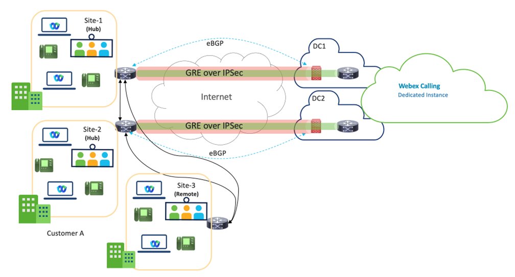
Virtual Connect - VPN je dizajn čvorišta, gde su lokacije čvorišta klijenta povezane sa DC1 i DC2 centara podataka namenske instance unutar određenog regiona.
Dva Hub sajta se preporučuju za bolju redundantnost, ali one Hub lokacija sa dva tunela je takođe podržan model primene.
Propusni opseg po tunelu je ograničen na 250 Mbps. To ensure effective failover, the combined traffic across both tunnels must not exceed 250 Mbps, as all traffic will be routed through one tunnel in the event of a failure.
Udaljene lokacije klijenta u okviru istog regiona, morale bi da se povežu sa lokacijama čvorišta preko WAN-a kupca i to nije Cisco-ova odgovornost za tu vezu.
Partners are expected to work closely with the Customers, ensuring the most optimal path is chosen for the Virtual Connect service region.
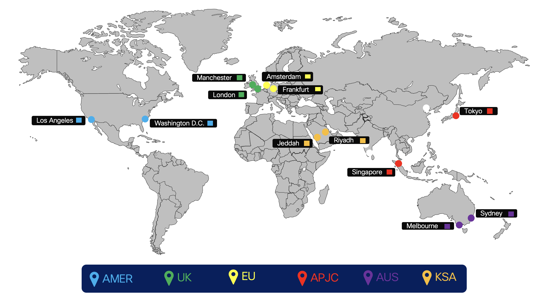
The below figure shows the Dedicated Instance cloud connectivity peering regions.
Usmeravanje
Proizvodni postupak za virtuelno povezivanje se primenjuje pomoću spoljnog BGP (eBGP) između namenske instance i opreme za premisu kupca (CPE). Cisco će reklamirati svoju mrežu za svaki suvišni DC u regionu na CPE klijenta i CPE je obavezan da reklamira podrazumevani put do kompanije Cisco.
-
Cisco održava i dodeljuje
-
IP adresa interfejsa tunela (prolazna veza za usmeravanje) Cisco dodeljuje iz naznačenog prostora deljene adrese (ne-javno usmeravanje)
-
Adresa za presačišanost tunela (Cisco's side)
-
Brojevi privatnih autonomnih sistema (ASNS) za konfiguraciju BGP usmeravanja kupca
-
Cisco dodeljuje iz naznačenog opsega privatne upotrebe: 64512 kroz 65534
-
-
-
eBGP koji se koristi za razmenu ruta između namenske instance i CPE
-
Cisco će podeliti dodeljenu /24 mrežu na 2/25 po jednu za svaki DC u odgovarajućem regionu
-
U Virtual Connect svakoj /25 mreži se oglašava nazad u CPE od strane kompanije Cisco preko odgovarajućeg point-to-point VPN tunela (prolazna veza)
-
CPE mora biti konfigurisan sa odgovarajućim eBGP komšijama. Ako koristite jedan CPE, koristiće se dva eBGP suseda, po jedan koji pokazuje na svaki udaljeni tunel. Ako koristite dva CPE- a, onda će svaki CPE imati po jednog eBGP komšiju koji će se potegnuti ka jednom udaljenom tunelu za CPE.
-
Cisco strana svakog GRE tunela (tunelski interfejs IP) konfigurisana je kao BGP komšija na CPE
-
CPE je obavezan da reklamira podrazumevanu rutu preko svakog od tunela
-
CPE je odgovornost za preraspodelu, kao što je propisano, naučenih puteva unutar mreže preduzeća rezača.
-
-
Pod uslovom otkazivanja veze koja nije neuspešna, jedan CPE će imati dva aktivna/aktivna tunela. Za dva CPE čvora, svaki CPE će imati po jedan aktivni tunel i oba CPE čvora bi trebalo da budu aktivna i da prolaze u saobraćaju. Prema scenariju koji se ne kvari, saobraćaj mora da se podeli na dva tunela koji idu na ispravne /25 destinacije, ako se jedan od tunela spusti, preostali tunel može da nosi saobraćaj za oba. Prema takvom scenariju otkazivanja, kada je mreža /25 u padu onda se mreža /24 koristi kao ruta pravljenja rezervne kopije. Cisco će poslati promet korisnika preko svog internog WAN-a prema DC-u koji je izgubio vezu.
Virtual connect traffic flow
Traffic flow when both the tunnels are up
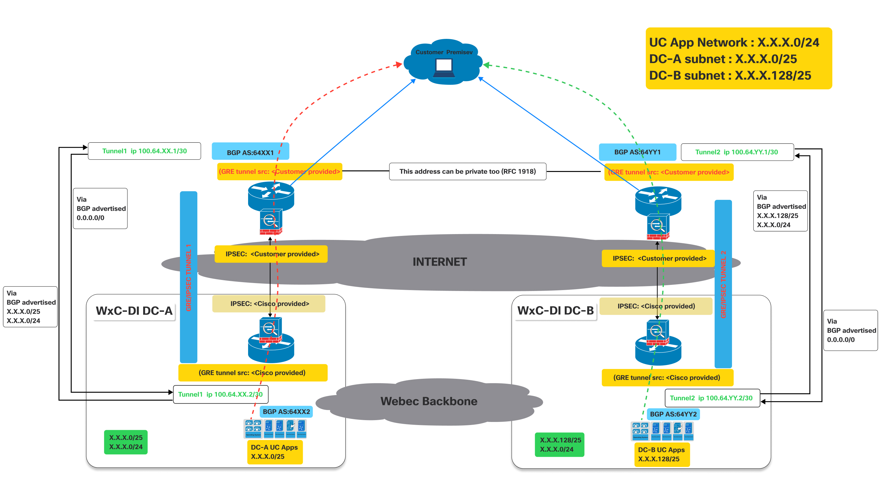
This image illustrates a Virtual Connect network architecture, detailing the traffic flow when both primary and secondary tunnels are operational.
It represents an active connectivity model for a customer to access UC applications hosted in Cisco's datacenters, leveraging dual GRE/IPSEC tunnels over the internet with BGP for route exchange.
Definitions:
- Customer Premise:
- This represents the customer's on-site network, where users and their devices (e.g., IP phones, computers running UC clients) are located.
- Traffic originating from here needs to reach the UC applications hosted in Cisco's datacenters.
- Cisco Webex Calling Dedicated Instance (Dedicated Instance) datacenters (WxC-DI DC-A and WxC-DI DC-B):
- These are Cisco's datacenters hosting the UC applications.
- DC-A and DC-B are geographically distinct, providing redundancy.
- Each datacenter has its own subnet for UC applications:
- DC-A subnet:X.X.X.0/25
- DC-B subnet:X.X.X.128/25
- GRE/IPsec Tunnels (Tunnel 1 and Tunnel 2):
- These are the secure, encrypted connections between the customer premise and the Cisco datacenter over the public internet.
- GRE (Generic Routing Encapsulation): This protocol is used to encapsulate various network layer protocols inside virtual point-to-point links. It allows routing protocols like BGP to operate over the tunnel.
- IPsec (Internet Protocol Security): This suite of protocols provides cryptographic security services (authentication, integrity, confidentiality) for IP communications. It encrypts the GRE-encapsulated traffic, ensuring secure data transmission over the Internet.
- Border Gateway Protocol (BGP):
- BGP is the routing protocol used to exchange routing information between the customer premise and the Cisco datacenters.
As shown in the above diagram, devices deployed on customer premises need to establish two GRE/IPSEC tunnels.
The naming conventions used below with XX / YY, DC-A DC-B are generic for all regions where Dedicated Instance is offered . These values will be unique for each region and the actual values for each region. The specific values are provided during the activation of the virtual connect.
On Cisco side the IPSec and GRE tunnels will be terminated on different devices. So the customer has to make sure to configure IPSec destination and GRE destination IPs on the devices accordingly. Customers can use the same IP for GRE and IPSEC if it is supported on their devices. Refer to the diagram above. The IP related values are provided during activation of the virtual connect on the portal.
- Tunnel 1: Connects the customer premise to "Dedicated Instance DC-A" (Data Center A) via the Internet. This tunnel uses BGP AS:64XX1 on the customer side and BGP AS:64XX2 on the Dedicated Instance DC-A side. IPSEC and GRE tunnel source configurations are split between customer-provided and Cisco-provided details.
- Tunnel 2: Connects the customer premise to "Dedicated Instance DC-B" (Data Center B) via the Internet. This tunnel uses BGP AS:64YY1 on the customer side and BGP AS:64YY2 on the Dedicated Instance DC-B side. Like Tunnel 1, IPSEC and GRE tunnel source configurations are shared between the customer and Cisco.
In BGP AS:64XX and BGP AS:64YY, XX and YY are specific to a particular region.
Once the GRE/IPSEC tunnels are established to Webex Calling Dedicated Instance datacenters (A and B), customer should receive the following routes advertised from Cisco over the corresponding BGP sessions.
- For DC-A: Routes advertised from Cisco will be X.X.X.0/25 and X.X.x.0/24. Optionally if IaaS is requested and configured for the customer routes Y.Y.Y.0/25 and Y.Y.Y.0/24 will be advertised from Cisco.
- For DC-B: Routes advertised from Cisco will be X.X.X.128/25 and X.X.x.0/24. Optionally if IaaS is requested and configured for the customer routes Y.Y.Y.128/25 and Y.Y.Y.0/24 will be advertised from Cisco.
- Customer needs to advertise the 0.0.0./0 route to Cisco thru both the connections (tunnels)
- Customer has to follow the longest prefix (/25) routes to send traffic to Cisco thru the respective tunnels when both tunnels are up.
- Cisco will return the traffic thru the same tunnels to keep traffic symmetric.
Traffic Flow:
- Traffic destined for "DC-A UC Apps" (X.X.X.0/25) from the customer premise flows through Tunnel 1.
- Traffic destined for "DC-B UC Apps" (X.X.X.128/25) from the customer premise flows through Tunnel 2.
Fail over scenario : traffic flow when one of the tunnel is down
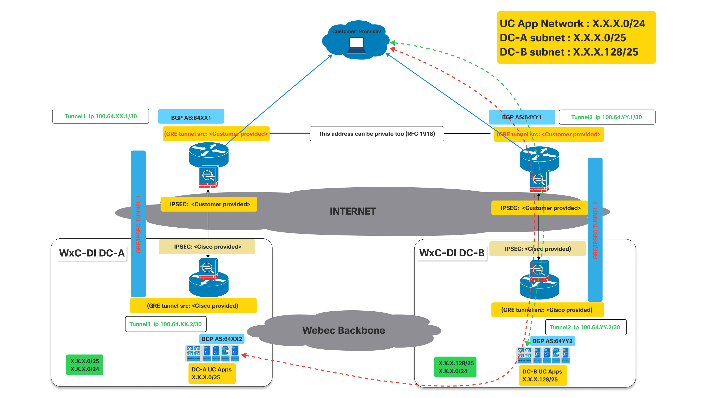
As shown in the above diagram when the tunnel to DC-A is down the bgp established thru tunnel to DC-A will go down.
Impact on BGP: When Tunnel 1 goes down, the BGP session over that tunnel will also go down. Consequently, DC-A will no longer be able to advertise its routes (specifically X.X.X.0/25) to the customer via this path. Hence the customer router will detect the path as unreachable.
Now since Tunnel 1 is down, the customer router at the customer premise will automatically remove the routes learned via Tunnel 1 from its routing table or mark them as unreachable.
- Traffic destined for the UC App Network (X.X.X.0/24) or the DC-A subnet (X.X.X.0/25) will then be redirected thru the working tunnel towards DC-B which continues to advertise the X.X.X.0/24 that includes the X.X.X.0/25 network.
- Similar behavior will be seen if tunnel to DC-B is down while tunnel to DC-A is still up.
Proces povezivanja
| 1 | |
| 2 | |
| 3 | |
| 4 |
Korak 1: CCW porudžbina
Virtual Connect je dodatak za namensku instancu u CCW.
| 1 |
Krećite se do lokacije ccW naručivanja, a zatim kliknite na dugme Prijavi se da biste se prijavili na lokaciju: |
| 2 |
Kreirajte procenu. |
| 3 |
Dodaj "A-FLEX-3" MJ. |
| 4 |
Izaberite opcije uređivanja. |
| 5 |
Na kartici za pretplatu koja se pojavljuje izaberite opcije i dodatke. |
| 6 |
U okviru Dodatni dodaci potvrdite izbor u polju za potvrdu pored stavke "Virtuelno povezivanje za namensku instancu". Ime MJ je "A-FLEX-DI-VC". |
| 7 |
Unesite količinu i broj regiona u kojima je potrebno virtuelno povezivanje. Količina virtuelnog povezivanja ne bi trebalo da premašuje ukupan broj regiona kupljenih za namensku instancu. Takođe, dozvoljena je samo jedna virtuelna porudžbina za povezivanje po regionu. |
| 8 |
Kada budete zadovoljni izborom, kliknite na dugme Proveri i sačuvaj u gornjem desnom delu stranice. |
| 9 |
Kliknite na dugme Sačuvaj i nastavi da biste dotizovali porudžbinu. Vaša finalizovana porudžbina se sada utiša u koordinatnu mrežu porudžbina. |
Korak 2: Aktiviranje virtuelnog povezivanja u kontrolnom čvorištu
| 1 |
Prijavite se u kontrolno čvorište https://admin.webex.com/login. |
| 2 |
U odeljku Usluge , dođite do pozivanja > Instacnce > u oblaku. |
| 3 |
Na kartici Virtuelno povezivanje navedena je kupljena količina virtuelnog povezivanja. Administrator sada može da klikne na dugme "Aktiviraj " da bi pokrenuo aktivaciju virtuelnog povezivanja.  Proces aktivacije mogu da pokrenu samo administratori sa ulogom "Customer Full admin". Dok administrator sa ulogom "Administrator samo za čitanje klijenta" može da vidi samo status. |
| 4 |
Kada kliknete na dugme "Aktiviraj ", prikazuje se obrazac "Aktiviraj virtuelno povezivanje" da bi administrator obezbedio tehničke detalje virtuelnog povezivanja neophodne za vršnjačke konfiguracije sa Cisco-ove strane. Obrazac takođe pruža statične informacije na Cisco-ovoj strani, zasnovane na izabranom regionu. Ove informacije će biti korisne za administratore klijenta da konfigurišu CPE na svojoj strani da bi uspostavili vezu. |
| 5 |
Kliknite na dugme Aktiviraj kada sva obavezna polja budu popunjena. |
| 6 |
Kada se obrazac za aktiviranje virtuelnog povezivanja dovrši za particluarnu oblast, kupac može da izveze obrazac za aktivaciju iz kontrolnog čvorišta, pozove > karticu Posvećena instanca > povezivanje u oblaku i klikne na postavke izvoza. 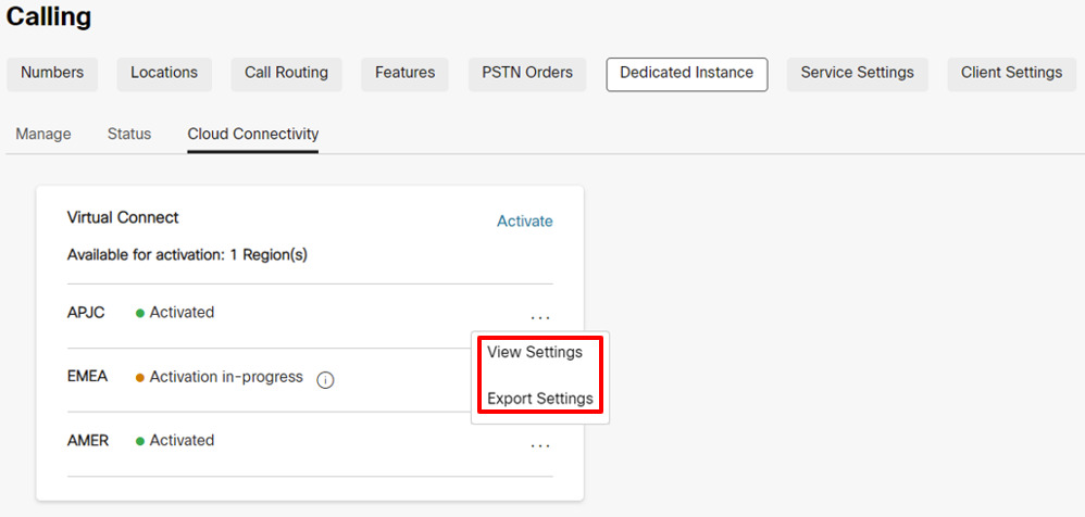 Due to security reasons the Authentication and BGP Password will not be available in the Exported document, but the administrator can view the same in Control Hub by clicking on View Settings under Control Hub, Calling > Dedicated Instance > Cloud Connectivity tab. |
Korak 3: Cisco izvršava konfiguraciju mreže
| 1 |
Kada se obrazac za aktiviranje virtuelnog povezivanja dovrši, status će biti ažuriran na activation In-Progress u pozivanje > namenske instance > Cloud Connectivity Virtual Connect kartica. |
| 2 |
Cisco will complete the required configurations on the Cisco’s side equipment within 5 business days. Kada se uspešno dovrši, status će biti ažuriran u "Aktivirano" za taj region u kontrolnom čvorištu. |
Korak 4: Klijent izvršava konfiguraciju mreže
|
Status se menja u "Aktivirano" da bi se administrator klijenta obavestio da je Cisco-jeva strana konfiguracija za IP VPN povezivanje ben dovršena na osnovu ulaza koje je obezbedio Klijent. Međutim, očekuje se da će administrator klijenta završiti svoju stranu konfiguracija na CPE-u i testirati puteve povezivanja da bi tunel Virtual Connect bio na mreži. U slučaju bilo kakvih problema sa kojima se suočava u vreme konfiguracije ili povezivanja, klijent može da se dopre do Cisco TAC-a za pomoć. |
Rešavanje problema
IPsec First Phase (IKEv2 Negotiation) Troubleshooting and Validation
The IPsec tunnel negotiation involves two phases, the IKEv2 phase and the IPsec phase. If the IKEv2 phase negotiation does not complete, then there is no initiation of a second IPsec phase. First, issue the command "show crypto ikev2 sa" (on Cisco equipment) or similar command on the third-party equipment to verify whether the IKEv2 session is active. If the IKEv2 session is not active, the potential reasons could be:
-
Interesting traffic does not triggers the IPsec tunnel.
-
The IPsec tunnel access list is misconfigured.
-
There is no connectivity between the customer and the Dedicated Instance IPsec tunnel endpoint IP.
-
The IKEv2 session parameters are not matching between the Dedicated Instance side and the customer side.
-
A firewall is blocking the IKEv2 UDP packets.
First, check the IPsec logs for any messages that show the progress of the IKEv2 tunnel negotiation. The logs may indicate where there is an issue with the IKEv2 negotiation. A lack of logging messages may also indicate that the IKEv2 session is not being activated.
Some common errors with the IKEv2 negotiation are:
-
The settings for the IKEv2 on the CPE side do not match the Cisco side, recheck the settings mentioned:
-
Check that the IKE version is version 2.
-
Verify that the Encryption and Authentication parameters match the expected encryption on the Dedicated Instance side.
When the "GCM" cipher is in use, the GCM protocol handles the authentication and set the authentication parameter to NULL.
-
Verify the lifetime setting.
-
Verify the Diffie Hellman modulus group.
-
Verify the Pseudo Random Function settings.
-
-
The access list for the crypto map is not set to:
-
Permit GRE (local_tunnel_transport_ip) 255.255.255.255 (remote_tunnel_transport_ip) 255.255.255.255" (or equivalent command)
The access list must be specifically for the "GRE" protocol and the "IP" protocol will not work.
-
If the log messages are not showing any negotiation activity for the IKEv2 phase, then a packet capture may be needed.
Dedicated Instance side may not always begin the IKEv2 exchange and may sometimes expect the customer CPE side to be the initiator.
Check the CPE side configuration for the following prerequisites for IKEv2 session initiation:
-
Check for an IPsec crypto access list for GRE traffic (protocol 50) from the CPE tunnel transport IP to the Dedicated Instance tunnel transport IP.
-
Ensure that the GRE tunnel interface is enabled for GRE keepalives, if the equipment does not support GRE keepalives then Cisco is notified because GRE keepalives will be enabled on the Dedicated Instance side on default.
-
Ensure that BGP is enabled and configured with the neighbor address of the Dedicated Instance tunnel IP.
When configured properly, the following begins the IPsec tunnel and the first-phase IKEv2 negotiation:
-
GRE keepalives from the CPE side GRE tunnel interface to the Dedicated Instance side GRE tunnel interface.
-
BGP neighbor TCP session from the CPE side BGP neighbor to the Dedicated Instance side BGP neighbor.
-
Ping from the CPE side tunnel IP address to the Dedicated Instance side tunnel IP address.
Ping cannot be the tunnel transport IP to tunnel transport IP, it must be tunnel IP to tunnel IP.
If a packet trace is needed for the IKEv2 traffic, set the filter for UDP and either port 500 (when no NAT device is in the middle of the IPsec endpoints) or port 4500 (when a NAT device is inserted in the middle of the IPsec endpoints).
Verify that IKEv2 UDP packets with port 500 or 4500 are sent and received to and from the DI IPsec IP address.
The Dedicated Instance datacenter may not always begin the first IKEv2 packet. The requirement is that the CPE device is capable of initiating the first IKEv2 packet toward the Dedicated Instance side.
If the local firewall allows it, then also attempt a ping to the remote IPsec address. If the ping is not successful from local to remote IPsec address, then perform a trace route to help, and determine where the packet is dropped.
Some firewalls and internet equipment may not allow trace route.
IPsec Second Phase (IPsec Negotiation) Troubleshooting and Validation
Verify that the IPsec first phase (that is, IKEv2 security association) is active before troubleshooting the IPsec second phase. Perform a "show crypto ikev2 sa" or equivalent command to verify the IKEv2 session. In the output, verify that the IKEv2 session has been up for more than a few second and that it is not bouncing. The session uptime shows as the session "Active Time" or equivalent in output.
Once the IKEv2 session verifies as up and active, Investigate the IPsec session. As with the IKEv2 session, perform a "show crypto ipsec sa" or equivalent command to verify the IPsec session. Both the IKEv2 session and the IPsec session must be active before the GRE tunnel is established. If the IPsec session does not show as active, check the IPsec logs for error messages or negotiation errors.
Some of the more common issues that may be encountered during the IPsec negotiations are:
The settings on the CPE side do not match the Dedicated Instance side, recheck the settings:
-
Verify that the Encryption and Authentication parameters match the settings on the Dedicated Instance side.
-
Verify the Perfect Forward Secrecy settings and that the match settings on the Dedicated Instance side.
-
Verify the lifetime settings.
-
Verify that the IPsec has been configured in tunnel mode.
-
Verify the source and destination IPsec addresses.
Tunnel Interface Troubleshooting and Validation
When the IPsec and IKEv2 sessions are verified as up and active, the GRE tunnel keepalive packets able to flow between the Dedicated Instance and CPE tunnel endpoints. If the tunnel interface is not showing up status, some common issues are:
-
The tunnel interface transport VRF does not match the VRF of the loopback interface (if VRF configuration is used on the tunnel interface).
If the VRF configuration is not used on the tunnel interface, this check can be ignored.
-
Keepalives are not enabled on the CPE side tunnel interface
If keepalives are not supported on the CPE equipment, then Cisco must be notified so that the default keepalives on the Dedicated Instance side are disabled as well.
If keepalives are supported, verify that the keepalives are enabled.
-
The mask or IP address of the tunnel interface is not correct and does not match the Dedicated Instance expected values.
-
The source or destination tunnel transport address is not correct and does not match the Dedicated Instance expected values.
-
A firewall is blocking GRE packets from sent into the IPsec tunnel or received from the IPsec tunnel (the GRE tunnel is transported over the IPsec tunnel)
A ping test should verify that the local tunnel interface is up and connectivity is good to the remote tunnel interface. Perform the ping check from the tunnel IP (not the transport IP) to the remote tunnel IP.
The crypto access list for the IPsec tunnel which is carrying the GRE tunnel traffic allows only GRE packets to cross. As a result, pings will not work from tunnel transport IP to remote tunnel transport IP.
The ping check results in a GRE packet that is generated from the source tunnel transport IP to destination tunnel transport IP while the payload of the GRE packet (the inside IP) will be the source and destination tunnel IP.
If the ping test is not successful and the preceding items are verified, then a packet capture may be required to ensure that the icmp ping is resulting in a GRE packet which is then encapsulated into an IPsec packet and then sent from the source IPsec address to the destination IPsec address. Counters on the GRE tunnel interface and the IPsec session counters can also help to show. if the send and receive packets are incrementing.
In addition to the ping traffic, the capture should also show keepalive GRE packets even during idle traffic. Finally, if BGP is configured, BGP keepalive packets should also be sent as GRE packets encapsulated in IPSEC packets as well over the VPN.
BGP Troubleshooting and Validation
BGP Sessions
BGP is required as the routing protocol over the VPN IPsec tunnel. The local BGP neighbor should establish an eBGP session with the Dedicated Instance BGP neighbor. The eBGP neighbor IP addresses are the same as the local and remote tunnel IP addresses. First ensure that the BGP session is up and then verify that the correct routes are being received from Dedicated Instance and the correct default route is sent to Dedicated Instance.
If the GRE tunnel is up, verify that a ping is successful between the local and the remote GRE tunnel IP. If the ping is successful but the BGP session is not coming up, then investigate the BGP log for BGP establishment errors.
Some of the more common BGP negotiation issues are:
-
The remote AS number does not match the AS number that is configured on the Dedicated Instance side, re-check the neighbor AS configuration.
-
The local AS number does not match what the Dedictaed Instance side is expecting, verify that the local AS number matches the expected Dedicated Instance parameters.
-
A firewall is blocking BGP TCP packets encapsulated in GRE packets from being sent into the IPsec tunnel or being received from the IPSEC tunnel
-
The remote BGP neighbor IP does not match the remote GRE tunnel IP.
BGP Route Exchange
Once the BGP session is verified for both tunnels, ensure that the correct routes are being send and received from the Dedicated Instance side.
The Dedicated Instance VPN solution expects two tunnels to be established from the customer/partner side. The first tunnel points to the Dedicated Instance datacenter A and the second tunnel points to the Dedicated Instance datacenter B. Both tunnels must be in active state and the solution requires an active/active deployment. Each Dedicated Instance datacenter will advertise it's local /25 route as well as a /24 backup route. When checking the incoming BGP routes from Dedicated Instance, ensure that the BGP session associated with the tunnel pointing to Dedicated Instance datacenter A receives the Dedicated Instance datacenter A /25 local route as well as the /24 backup route. In addition, ensure that the tunnel pointing to Dedicated Instance datacenter B recieves the Dedicated Instance datacenter B /25 local route as well as the /24 backup route. Note that the /24 backup route will be the same route advertised out of Dedicated Instance datacenter A and Dedicated Instance datacenter B.
Redundancy is provided to a Dedicated Instance datacenter if the tunnel interface to that datacenter goes down. If connectivity to Dedicated Instance datacenter A is lost, then traffic will be forwarded from Dedicated Instance datacenter B to datacenter A. In this scenario, the tunnel to datacenter B will use the datacenter B /25 route to send traffic to datacenter B and the tunnel to datacenter B will use the backup /24 route to send traffic to datacenter A via datacenter B.
It is important that, when both tunnels are active that datacenter A tunnel is not used to send traffic to datacenter B and vice versa. In this scenario, if traffic is sent to datacenter A with a destination of datacenter B, datacenter A will forward the traffic to datacenter B and then datacenter B will attempt to send traffic back to the source via the datacenter B tunnel. This will result in sub-optimal routing and may also break traffic traversing firewalls. Therefore, it is important for both tunnels to be in an active/active configuration during normal operation.
The 0.0.0.0/0 route must be advertised from the customer side to the Dedicated Instance datacenter side. More specific routes will not be accepted by the Dedicated Instance side. Ensure that the 0.0.0.0/0 route is advertised out of both the Dedicated Instance datacenter A tunnel and the Dedicated Instance datacenter B tunnel.
MTU Configuration
In the Dedicated Instance side, two features are enabled to dynamically adjust MTU for large packet sizes. The GRE tunnel adds more headers to the IP packets flowing through the VPN session. The IPsec tunnel adds the additional headers on top of the GRE headers will further reduce the largest MTU allowed over the tunnel.
The GRE tunnel adjusts MSS feature and GRE tunnel path in the MTU discovery feature is enabled on the Dedicated Instance side. Configure "ip tcp adjust-mss 1350" or equivalent command as well as "tunnel path\u0002mtu-discovery" or equivalent command on the customer side to help with the dynamic adjusting of MTU of traffic through the VPN tunnel.


