
תודה על המשוב.
קביעת התצורה של שער מקומי ב-Cisco IOS XE עבור Webex Calling
 משוב?
משוב?סקירה
Webex Calling תומך כעת בשתי גרסאות של Local Gateway:
-
שער מקומי
-
שער מקומי עבור Webex לממשל
-
לפני שתתחיל, הבן את דרישות רשת הטלפונים הציבורית (PSTN) והשער המקומי (LGW) המבוססות על המקום עבור Webex Calling. ראה ארכיטקטורה מועדפת של Cisco עבור Webex Calling למידע נוסף.
-
מאמר זה מניח שקיימת פלטפורמת שער מקומי ייעודית ללא תצורת קול קיימת. אם תשנה פריסת PSTN קיימת או פריסת CUBE Enterprise לשימוש כפונקציית השער המקומי עבור Webex Calling, יש לשים לב היטב לתצורה. ודא שלא תפריע לזרימות השיחות והפונקציונליות הקיימות עקב השינויים שאתה מבצע.
ההליכים מכילים קישורים לתיעוד עזר של פקודות שבו ניתן ללמוד עוד על אפשרויות הפקודות השונות. כל קישורי הפקודות עוברים אל Webex Managed Gateways Command Reference אלא אם כן צוין אחרת (במקרה כזה, קישורי הפקודות עוברים אל Cisco IOS Voice Command Reference). ניתן לגשת לכל המדריכים הללו בכתובת Cisco Unified Border Element Command References.
למידע על חבילות SBC נתמכות של צד שלישי, עיין בתיעוד המוצר המתאים.
ישנן שתי אפשרויות להגדרת השער המקומי עבור רשת האינטרנט Webex Calling שלך:
-
תא מטען מבוסס רישום
-
תא מטען מבוסס תעודה
השתמש בזרימת המשימות תחת שער מקומי מבוסס רישום או שער מקומי מבוסס אישורים כדי להגדיר את שער מקומי עבור רשת ה-Webex Calling שלך.
ראה התחל עם Local Gateway למידע נוסף על סוגי רשתות תא מטען שונות. בצע את השלבים הבאים בשער המקומי עצמו, באמצעות ממשק שורת הפקודה (CLI). אנו משתמשים בפרוטוקול Session Initiation Protocol (SIP) וב-Transport Layer Security (TLS) כדי לאבטח את ה-trunk ובפרוטוקול Secure Real Time Protocol (SRTP) כדי לאבטח את המדיה בין ה-Local Gateway ל-Webex Calling.
-
בחר CUBE כשער המקומי שלך. Webex לממשל אינו תומך כעת בבקרי גבולות הפעלה (SBC) של צד שלישי. כדי לעיין ברשימה העדכנית ביותר, ראה התחל עם Local Gateway.
- התקן את Cisco IOS XE Dublin 17.12.1a או גרסאות מאוחרות יותר עבור כל שערי Webex לממשל מקומיים.
-
כדי לעיין ברשימת רשויות האישורים הבסיסיות (CA) ש-Webex for Government תומכות בהן, ראה רשויות אישורי בסיסיות עבור Webex for Government.
-
לפרטים על טווחי היציאות החיצוניות עבור Local Gateway ב-Webex for Government, ראה דרישות רשת עבור Webex for Government (FedRAMP).
שער מקומי עבור Webex לממשל אינו תומך בדברים הבאים:
-
STUN/ICE-Lite לאופטימיזציה של נתיב המדיה
-
פקס (T.38)
כדי להגדיר את Local Gateway עבור Webex Calling trunk שלך ב-Webex for Government, השתמש באפשרות הבאה:
-
תא מטען מבוסס תעודה
השתמש בזרימת המשימות תחת שער מקומי מבוסס אישורים כדי להגדיר את השער המקומי עבור רשת האינטרנט של Webex Calling שלך. לפרטים נוספים על אופן קביעת התצורה של שער מקומי מבוסס אישורים, ראה קביעת תצורה של trunk מבוסס אישורים של Webex Calling.
חובה להגדיר צפני GCM תואמי FIPS כדי לתמוך ב-Local Gateway עבור Webex for Government. אם לא, הגדרת השיחה נכשלת. לקבלת פרטי תצורה, ראה הגדרת trunk מבוסס תעודת Webex Calling.
Webex לממשל אינו תומך ב-Local Gateway מבוסס רישום.
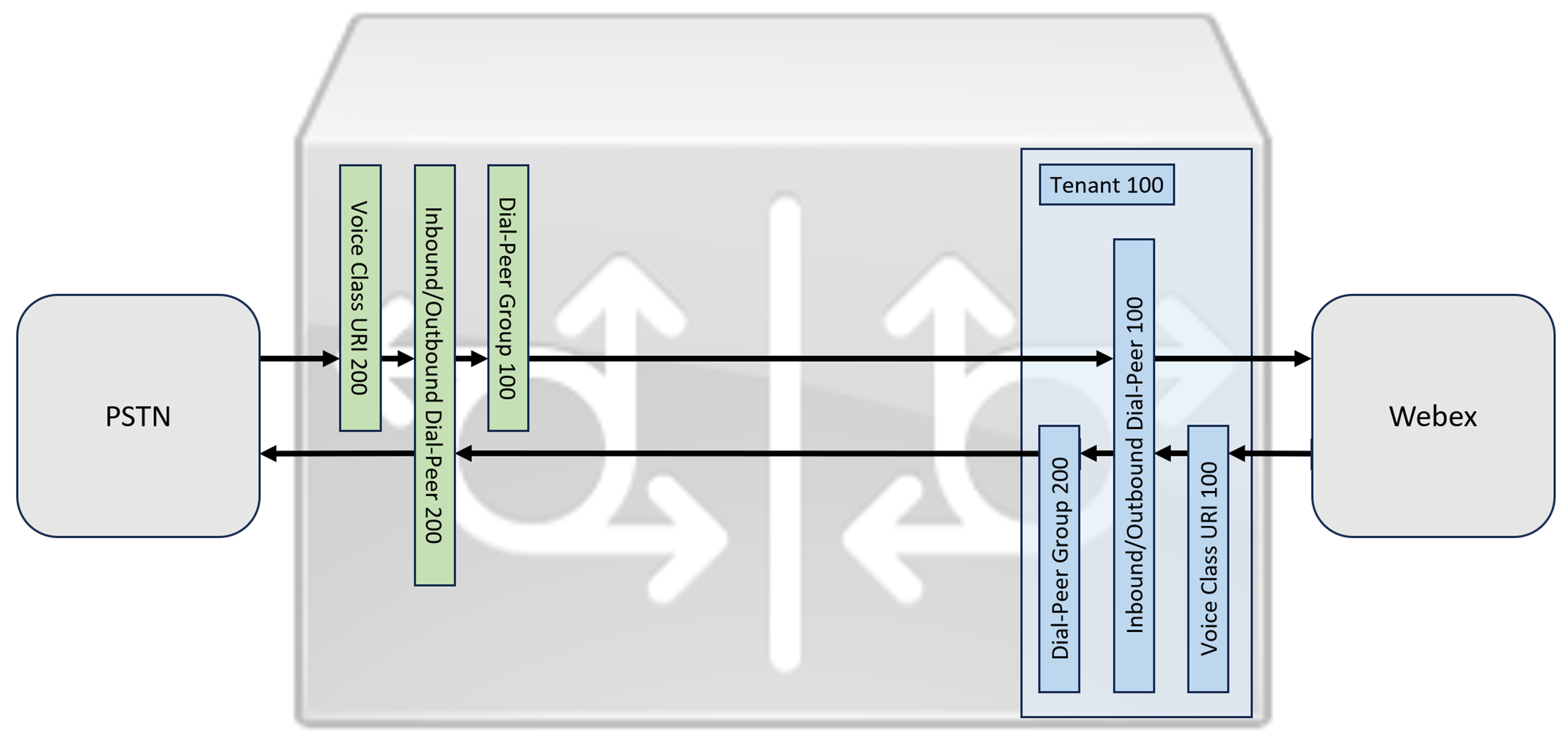
סעיף זה מתאר כיצד להגדיר אלמנט גבול מאוחד של Cisco (CUBE) כשער מקומי עבור Webex Calling, באמצעות רשת SIP רישום. החלק הראשון של מסמך זה ממחיש כיצד להגדיר שער PSTN פשוט. במקרה זה, כל השיחות מה-PSTN מנותבות ל-Webex Calling וכל השיחות מ-Webex Calling מנותבות ל-PSTN. התמונה למטה מדגישה פתרון זה ואת תצורת ניתוב השיחות ברמה גבוהה שתתבצע.
בתכנון זה, נעשה שימוש בתצורות העיקריות הבאות:
-
דיירי מחלקת קול: משמש ליצירת תצורות ספציפיות לתא המטען.
-
URI של מחלקת קול: משמש לסיווג הודעות SIP לבחירת עמית לחיוג נכנס.
-
עמית חיוג נכנס: מספק טיפול בהודעות SIP נכנסות וקובע את הנתיב היוצא באמצעות קבוצת חיוג-עמית.
-
קבוצת עמיתים לחיוג: מגדיר את עמיתי החיוג היוצא המשמשים לניתוב שיחות קדימה.
-
עמית חיוג יוצא: מספק טיפול בהודעות SIP יוצאות ונותב אותן ליעד הנדרש.
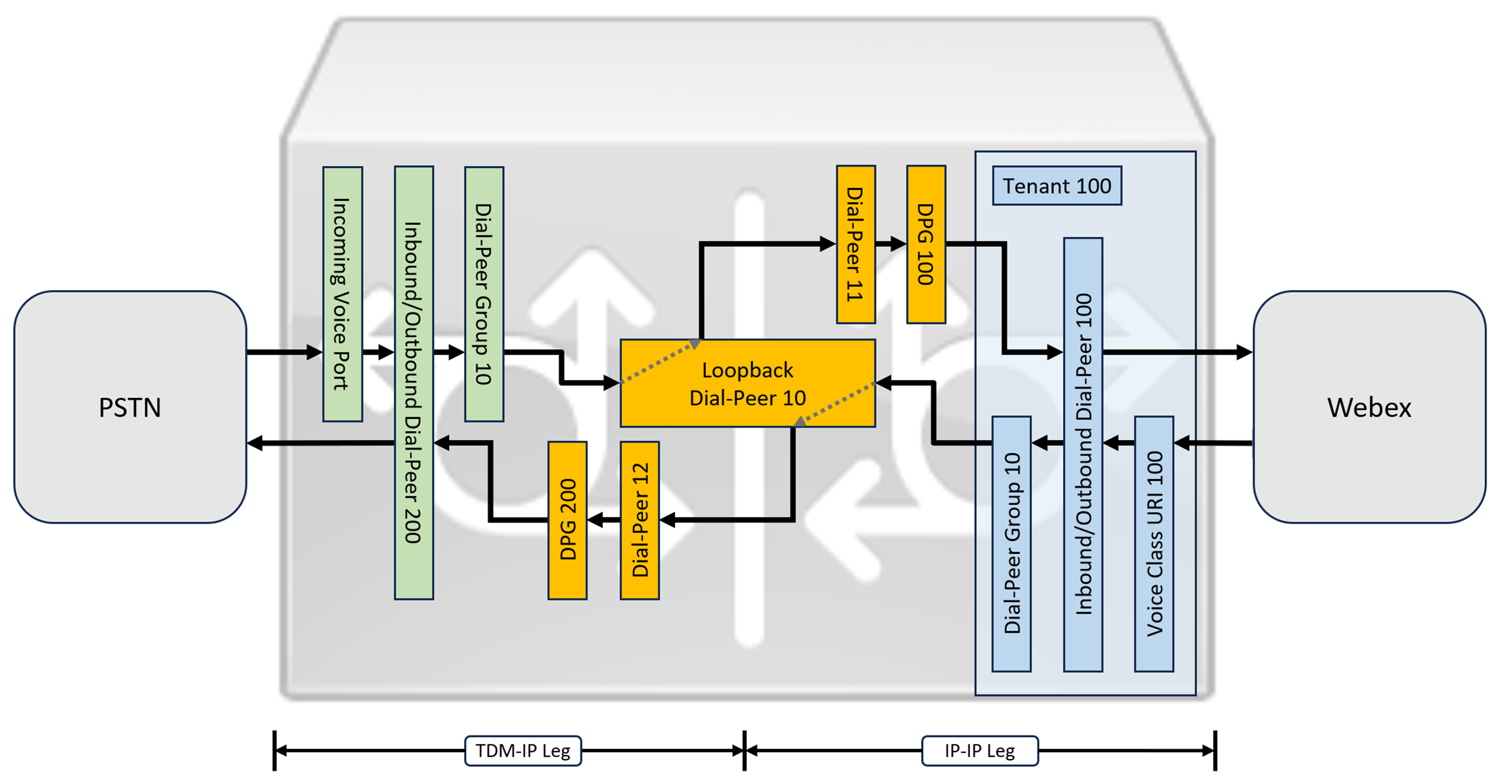
בעוד ש-IP ו-SIP הפכו לפרוטוקולי ברירת המחדל עבור רשתות PSTN, מעגלי ISDN מסוג TDM (Time Division Multiplexing) עדיין נמצאים בשימוש נרחב ונתמכים עם רשתות Webex Calling. כדי לאפשר אופטימיזציה של מדיה של נתיבי IP עבור שערים מקומיים עם זרימת שיחות TDM-IP, כיום יש צורך להשתמש בתהליך ניתוב שיחות דו-שלבי. גישה זו משנה את תצורת ניתוב השיחות המוצגת לעיל, על ידי הכנסת קבוצה של עמיתים פנימיים לחיוג חוזר בין Webex Calling ו-PSTN trunks כפי שמודגם בתמונה למטה.
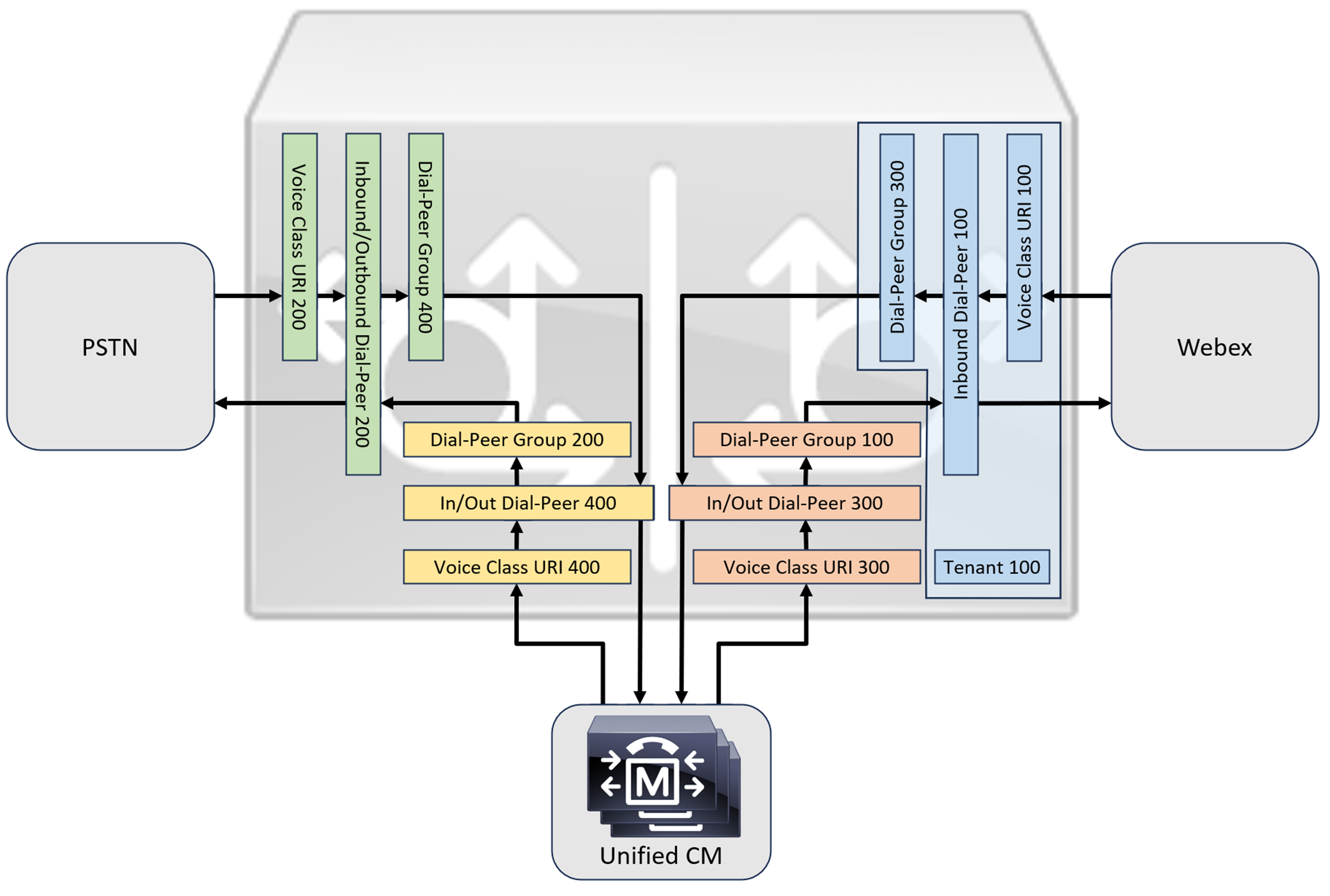
בעת חיבור פתרון Cisco Unified Communications Manager מקומי עם Webex Calling, ניתן להשתמש בתצורת שער PSTN פשוטה כבסיס לבניית הפתרון המוצג בתרשים הבא. במקרה זה, מנהל התקשורת המאוחד מספק ניתוב וטיפול מרכזיים בכל שיחות PSTN ו-Webex Calling.
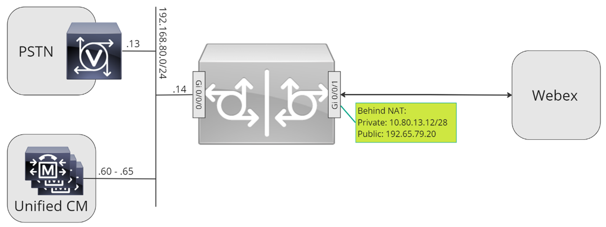
לאורך מסמך זה, נעשה שימוש בשמות המארחים, כתובות ה-IP והממשקים המוצגים בתמונה הבאה.
השתמש בהנחיות התצורה בשאר מסמך זה כדי להשלים את תצורת השער המקומי שלך באופן הבא:
-
שלב 1: הגדרת קישוריות ואבטחה בסיסיים של הנתב
-
שלב 2: הגדרת רשת שיחות Webex
בהתאם לארכיטקטורה הנדרשת, בצע אחת מהפעולות הבאות:
-
שלב 3: הגדרת שער מקומי עם trunk של SIP PSTN
-
שלב 4: הגדרת שער מקומי עם סביבת CM מאוחדת קיימת
אוֹ:
-
שלב 3: הגדרת שער מקומי עם TDM PSTN trunk
תצורת בסיס
השלב הראשון בהכנת נתב Cisco שלך כשער מקומי עבור Webex Calling הוא בניית תצורה בסיסית שמאבטחת את הפלטפורמה שלך ומבססת קישוריות.
-
כל פריסות ה-Local Gateway המבוססות על רישום דורשות Cisco IOS XE 17.6.1a או גרסאות מאוחרות יותר. מומלץ להשתמש ב-Cisco IOS 17.12.2 או גרסה מתקדמת יותר. לגרסאות המומלצות, עיינו בדף Cisco Software Research. חפש את הפלטפורמה ובחר אחת מהגרסאות המוצעות.
-
נתבים מסדרת ISR4000 חייבים להיות מוגדרים עם רישיונות טכנולוגיית תקשורת מאוחדת (Unified Communications) ורישיונות טכנולוגיית אבטחה (Security).
-
נתבים מסדרת Catalyst Edge 8000 המצוידים בכרטיסי קול או מערכות זיהוי דיגיטליות (DSP) דורשים רישיון DNA Advantage. נתבים ללא כרטיסי קול או מערכות זיהוי דיגיטליות (DSP) דורשים רישיון DNA Essentials לפחות.
-
-
בנה תצורת בסיס לפלטפורמה שלך שתתאים למדיניות העסקית שלך. בפרט, יש להגדיר ולאמת את הדברים הבאים:
-
NTP
-
רשימות בקרת גישה (ACL)
-
אימות משתמש וגישה מרחוק
-
DNS
-
ניתוב IP
-
כתובות IP
-
-
הרשת ל-Webex Calling חייבת להשתמש בכתובת IPv4.
-
העלה את חבילת רשות האישורים הבסיסית של Cisco לשער המקומי.
בעת הגדרת צד הדייר להתחברות עם Webex Calling, רק כתובות מבוססות SRV נתמכות.
הגדרת תצורה
| 1 |
ודא שאתה מקצה כתובות IP תקפות וניתנות לניתוב לכל ממשקי שכבה 3, לדוגמה:
|
| 2 |
הגן על פרטי הרישום וה-STUN בנתב באמצעות הצפנה סימטרית. הגדר את מפתח ההצפנה הראשי ואת סוג ההצפנה באופן הבא:
|
| 3 |
צור נקודת אמון PKI מסוג placeholder. נדרשת נקודת אמון זו כדי להגדיר TLS בהמשך. עבור trunks מבוססי רישום, נקודת אמון זו אינה דורשת אישור - כפי שנדרש עבור trunk מבוסס אישור. |
| 4 |
הפעל בלעדיות TLS1.2 וציין את נקודת האמון המוגדרת כברירת מחדל באמצעות פקודות התצורה הבאות. עדכן את פרמטרי התעבורה כדי להבטיח חיבור מאובטח ואמין לצורך רישום: הפקודה
|
| 5 |
התקן את חבילת רשות האישור הבסיסית של Cisco, הכוללת את אישור Root CA1 המסחרי של IdenTrust המשמש את Webex Calling. השתמש בפקודה crypto pki trustpool import clean url כדי להוריד את חבילת האישורים הבסיסיים מכתובת האתר שצוינה, ולנקות את מאגר האישורים הנוכחי, לאחר מכן התקן את חבילת האישורים החדשה: אם עליך להשתמש בפרוקסי לגישה לאינטרנט באמצעות HTTPS, הוסף את התצורה הבאה לפני ייבוא חבילת CA: ip http לקוח פרוקסי שרת yourproxy.com יציאת פרוקסי 80 |
| 1 |
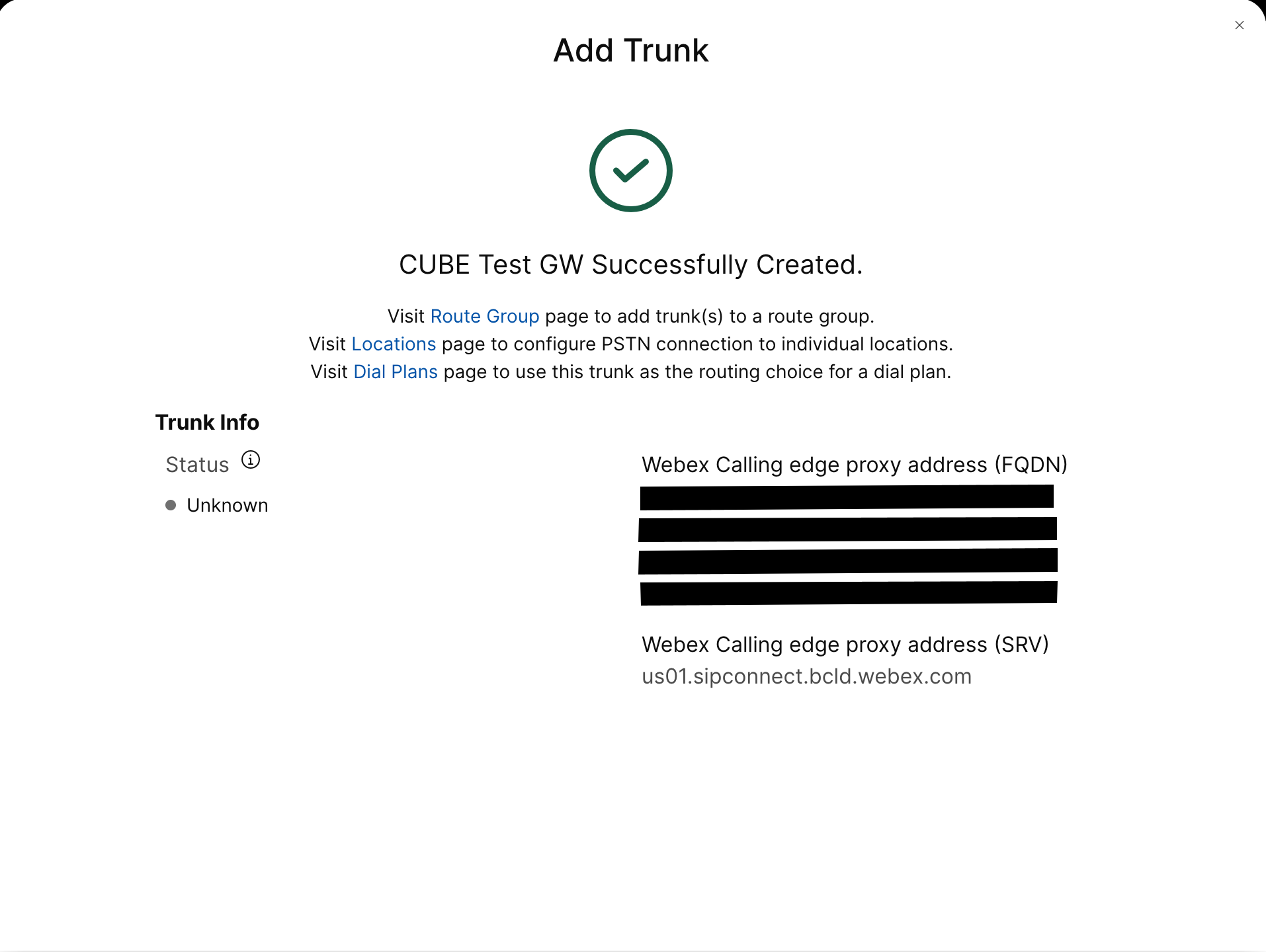
צור trunk PSTN מבוסס רישום עבור מיקום קיים במרכז הבקרה. רשום לעצמך את פרטי תא המטען המסופקים לאחר יצירת תא המטען. הפרטים המודגשים באיור משמשים בשלבי התצורה במדריך זה. למידע נוסף, ראה הגדרת רשתות גז, קבוצות ניתוב ותוכניות חיוג עבור Webex Calling. 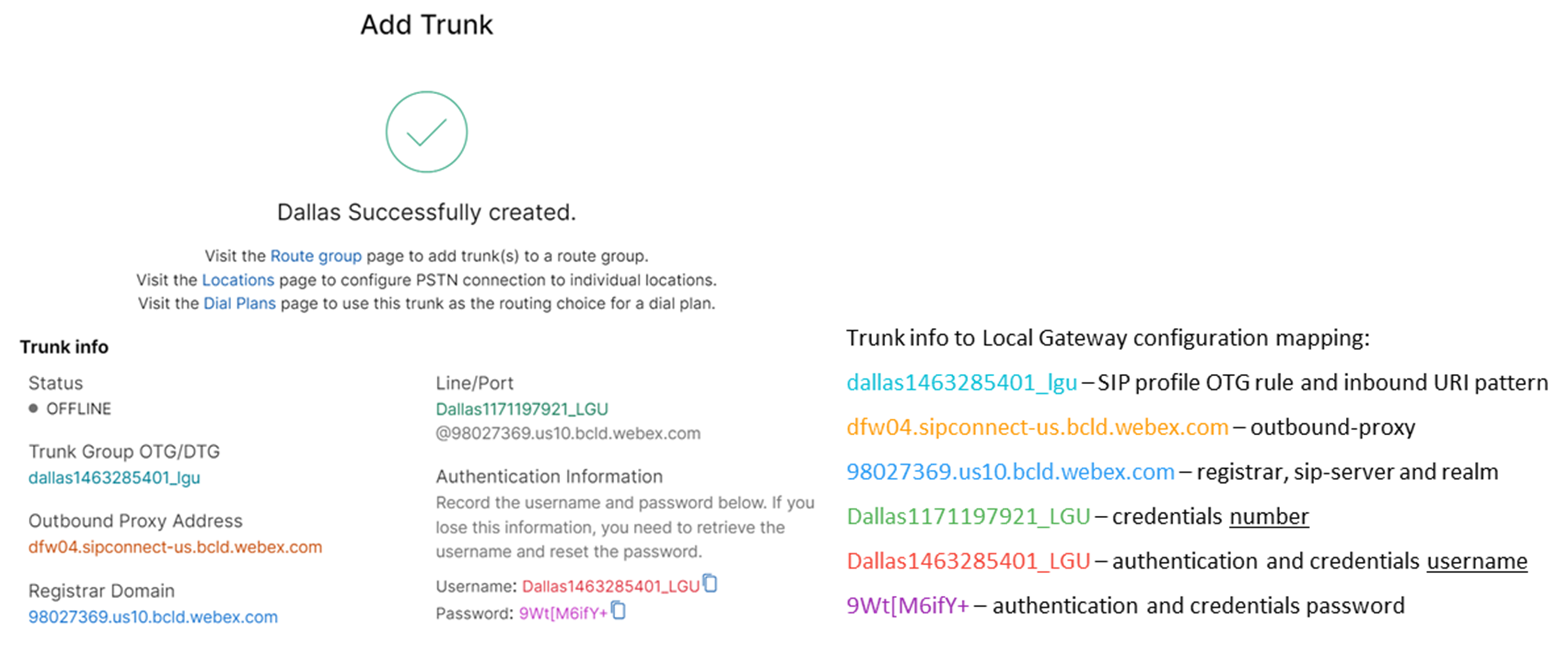 |
| 2 |
הזן את הפקודות הבאות כדי להגדיר את CUBE כשער מקומי של Webex Calling: הנה הסבר על השדות עבור התצורה:
מאפשר תכונות של Cisco Unified Border Element (CUBE) בפלטפורמה. סטטיסטיקות תקשורתמאפשר ניטור מדיה בשער המקומי. סטטיסטיקות מדיה בכמות גדולהמאפשר למישור הבקרה לבצע סקר במישור הנתונים עבור סטטיסטיקות של שיחות בכמות גדולה. למידע נוסף על פקודות אלו, ראו מדיה. אפשר חיבורים בין סימפוניםהפעל פונקציונליות סוכן משתמש בסיסי של SIP גב אל גב של CUBE. למידע נוסף, ראה אפשר חיבורים. כברירת מחדל, העברת פקס T.38 מופעלת. למידע נוסף, ראה פרוטוקול פקס t38 (שירות קולי). מאפשר STUN (Session Traversal of UDP through NAT) באופן גלובלי.
למידע נוסף, ראו stun flowdata agent-id ו- stun flowdata shared-secret. מטען אסימטרי מלאמגדיר תמיכה במטענים אסימטריים של SIP עבור טעינות DTMF ו-codec דינמי. למידע נוסף, ראו מטען אסימטרי. הצעה מוקדמת כפויהמאלץ את השער המקומי לשלוח מידע SDP בהודעת ה-INVITE הראשונית במקום להמתין לאישור מהעמית השכן. למידע נוסף על פקודה זו, ראו הצעה מוקדמת. |
| 3 |
הגדר קודק מחלקת קול 100 המאפשר קודקים של G.711 עבור כל ה-trunks בלבד. גישה פשוטה זו מתאימה לרוב הפריסות. במידת הצורך, ניתן להוסיף לרשימה סוגי קודקים נוספים הנתמכים על ידי מערכות המקור והסיום כאחד. פתרונות מורכבים יותר הכוללים קידוד מחדש באמצעות מודולי DSP נתמכים, אך אינם כלולים במדריך זה. הנה הסבר על השדות עבור התצורה: קודק מחלקת קול 100משמש כדי לאפשר רק קודקים מועדפים עבור שיחות SIP trunk. למידע נוסף, ראו קודק מחלקת קול. |
| 4 |
הגדר את voice class stun-usage 100 כדי להפעיל ICE ב-Webex Calling trunk. הנה הסבר על השדות עבור התצורה: שימוש בהלם בקרח לייטמשמש להפעלת ICE-Lite עבור כל עמיתים לחיוג הפונים ל-Webex Calling כדי לאפשר אופטימיזציה של מדיה במידת האפשר. למידע נוסף, ראו שימוש בהלם ברמת קול ו- שימוש בהלם ברמת קרח לייט. אופטימיזציה של המדיה נערכת במשא ומתן במידת האפשר. אם שיחה דורשת שירותי מדיה בענן, כגון הקלטה, לא ניתן לבצע אופטימיזציה של המדיה. |
| 5 |
הגדר את מדיניות הצפנת המדיה עבור תעבורת Webex. הנה הסבר על השדות עבור התצורה: קול מחלקה srtp-crypto 100מציין את SHA1_80 כהצעות ה-CUBE היחידות של חבילת הצפנת SRTP ב-SDP בהודעות הצעה ותשובה. שיחות Webex תומכות רק ב-SHA1_80. למידע נוסף, ראה מחלקת קול srtp-crypto. |
| 6 |
הגדר תבנית לזיהוי קריאות ל- Local Gateway trunk בהתבסס על פרמטר היעד של trunk: הנה הסבר על השדות עבור התצורה: קול מחלקה URI 100 sipמגדיר תבנית להתאמה של הזמנת SIP נכנסת לעמית חיוג trunk נכנס. בעת הזנת תבנית זו, השתמש ב-dtg= ולאחר מכן ב-Trunk. OTG/DTG הערך שסופק במרכז הבקרה בעת יצירת ה-trunk. למידע נוסף, ראו uri של מחלקת קול. |
| 7 |
הגדר את פרופיל sip 100, אשר ישמש לשינוי הודעות SIP לפני שליחתן ל-Webex Calling.
הנה הסבר על השדות עבור התצורה:
ספק שירותי PSTN בארצות הברית או בקנדה יכול להציע אימות זיהוי מתקשר עבור שיחות ספאם והונאה, עם התצורה הנוספת המוזכרת במאמר אינדיקציה של שיחת ספאם או הונאה ב-Webex Calling. |
| 8 |
הגדרת רשת שיחות Webex: |
| 9 |
כדי להגדיר התקני רשת כגון CUBE ולהעביר כותרות של Session Initiation Protocol (SIP) שההתקן אינו מעבד, השתמש בפקודות אלה. פקודות אלה מאפשרות למכשיר להעביר דרך כותרות SIP שאינן נתמכות, כולל כותרות מיקום גיאוגרפי ו-PIDF-LO (פורמט נתוני מידע נוכחות - אובייקט מיקום), בשער המקומי. פונקציונליות זו תומכת בשירותי Nomadic E911 על ידי הבטחת שמירה והעברת מידע קריטי על מיקום בצורה נכונה. |
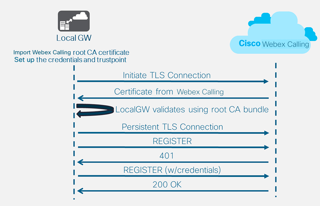
לאחר הגדרת הדייר 100 ותצורת עמית חיוג SIP VoIP, השער יוזם חיבור TLS לכיוון Webex Calling. בשלב זה, SBC הגישה מציג את האישור שלו לשער המקומי. השער המקומי מאמת את אישור ה-SBC של גישת Webex Calling באמצעות חבילת הבסיס של CA שעודכנה קודם לכן. אם האישור מזוהה, נוצרת הפעלת TLS מתמשכת בין השער המקומי לבין SBC של גישת Webex Calling. לאחר מכן, השער המקומי יכול להשתמש בחיבור מאובטח זה כדי להירשם ל-Webex access SBC. כאשר הרישום מתבקש לאימות:
-
הפרמטרים username, passwordו- realm מתצורת credentials משמשים בתגובה.
-
כללי השינוי בפרופיל SIP 100 משמשים להמרת כתובת URL של SIPS בחזרה ל-SIP.
הרישום מצליח כאשר מתקבל אישור 200 מ-SBC הגישה.
לאחר שבניתם trunk (תא מטען) לכיוון Webex Calling לעיל, השתמשו בתצורה הבאה כדי ליצור trunk לא מוצפן לכיוון ספק PSTN מבוסס SIP:
אם ספק השירות שלך מציע רשת PSTN מאובטחת, תוכל לבצע תצורה דומה לזו המפורטת לעיל עבור רשת Webex Calling. CUBE תומך בניתוב שיחות מאובטח.
אם אתה משתמש ב-TDM / IPS (ISDN PSTN trunk), דלג לסעיף הבא הגדרת שער מקומי עם TDM PSTN trunk.
כדי להגדיר ממשקי TDM עבור רגלי שיחות PSTN בשערי Cisco TDM-SIP, ראה הגדרת ISDN PRI.
| 1 |
הגדר את ה-uri של מחלקת הקול הבאה כדי לזהות שיחות נכנסות מרשת ה-PSTN: הנה הסבר על השדות עבור התצורה: קול מחלקה URI 200 sipמגדיר תבנית להתאמה של הזמנת SIP נכנסת לעמית חיוג trunk נכנס. בעת הזנת תבנית זו, השתמש בכתובת ה-IP של שער ה-IP PSTN שלך. למידע נוסף, ראו uri של מחלקת קול. |
| 2 |
הגדר את עמית החיוג הבא של IP PSTN: הנה הסבר על השדות עבור התצורה: מגדיר עמית חיוג VoIP עם תגית 200 ומספק תיאור משמעותי לנוחות הניהול ופתרון בעיות. למידע נוסף, ראו קול חיוג-עמית. תבנית-יעד גרועה.גרועהנדרשת תבנית יעד דמה בעת ניתוב שיחות יוצאות באמצעות קבוצת עמיתים לחיוג נכנס. במקרה זה ניתן להשתמש בכל תבנית יעד תקפה. למידע נוסף, ראו destination-pattern (ממשק). פרוטוקול הפעלה sipv2מציין שעמית חיוג זה מטפל ברגלי שיחות SIP. למידע נוסף, ראה פרוטוקול סשן (חיוג עמית). יעד סשן ipv4: 192.168.80.13מציין את כתובת היעד עבור שיחות הנשלחות לספק PSTN. זה יכול להיות כתובת IP או שם מארח DNS. למידע נוסף, ראה יעד סשן (עמית חיוג VoIP). URI נכנס דרך 200מציין את מחלקת הקול המשמשת להתאמת שיחות נכנסות לעמית חיוג זה באמצעות URI הכותרת INVITE VIA. למידע נוסף, ראה כתובת URL נכנסת. קול-מחלקה sip asserted-id pai
(אופציונלי) מפעיל את עיבוד כותרת P-Asserted-Identity ושולט באופן השימוש בו עבור trunk PSTN. אם משתמשים בפקודה זו, זהות הצד המתקשר שסופקה על ידי עמית החיוג הנכנס תשמש עבור כותרות ה-From וה-P-Asserted-Identity היוצאות. אם פקודה זו אינה בשימוש, זהות הצד הקורא המסופקת על ידי עמית החיוג הנכנס תשמש עבור כותרות ה-From ו-Remote-Party-ID היוצאות. למידע נוסף, ראה voice-class sip asserted-id. ממשק מקור-בקרת קשירה GigabitEthernet0/0/0
מגדיר את ממשק המקור ואת כתובת ה-IP המשויכת להודעות הנשלחות ל-PSTN. למידע נוסף, ראה bind. קשירת ממשק מקור מדיה GigabitEthernet0/0/0מגדיר את ממשק המקור ואת כתובת ה-IP המשויכת למדיה הנשלחת ל-PSTN. למידע נוסף, ראה bind. קודק מסוג קול 100מגדיר את עמית החיוג לשימוש ברשימת מסנני הקודקים המשותפים 100. למידע נוסף, ראו קודק מסוג קול. dtmf-relay rtp-nteמגדיר RTP-NTE (RFC2833) כיכולת DTMF הצפויה ברגל השיחה. למידע נוסף, ראה DTMF Relay (קול מעל IP). אין וואדיםמשבית את זיהוי הפעילות הקולית. למידע נוסף, ראה vad (חיוג עמית). |
| 3 |
אם אתה מגדיר את השער המקומי שלך לניתוב שיחות רק בין Webex Calling ל-PSTN, הוסף את תצורת ניתוב השיחות הבאה. אם אתם מגדירים את ה-Local Gateway שלכם עם פלטפורמת Unified Communications Manager, דלגו לסעיף הבא. |
לאחר שבניתם trunk עבור Webex Calling, השתמשו בתצורה הבאה כדי ליצור trunk TDM עבור שירות PSTN שלכם עם ניתוב שיחות בלולאה חזרה כדי לאפשר אופטימיזציה של מדיה ברגל שיחת Webex.
אם אינך זקוק לאופטימיזציה של מדיה IP, בצע את שלבי התצורה עבור trunk של SIP PSTN. השתמש ביציאת קול ועמית חיוג POTS (כפי שמוצג בשלבים 2 ו-3) במקום עמית חיוג VoIP של PSTN.
| 1 |
תצורת חיוג-עמית בלולאה חזרה משתמשת בקבוצות חיוג-עמית ותגי ניתוב שיחות כדי להבטיח ששיחות יעברו כראוי בין Webex ל-PSTN, מבלי ליצור לולאות ניתוב שיחות. הגדר את כללי התרגום הבאים שישמשו להוספה והסרה של תגי ניתוב שיחות: הנה הסבר על השדות עבור התצורה: כלל תרגום קולימשתמש בביטויים רגולריים המוגדרים בכללים כדי להוסיף או להסיר תגי ניתוב שיחות. ספרות מעל עשרוניות ('A') משמשות להוספת בהירות לפתרון בעיות. בתצורה זו, התג שנוסף על ידי פרופיל התרגום 100 משמש להכוונת שיחות מ-Webex Calling אל ה-PSTN דרך עמיתים לחיוג לולאה חוזר. באופן דומה, התג שנוסף על ידי פרופיל התרגום 200 משמש להכוונת שיחות מה-PSTN לכיוון Webex Calling. פרופילי תרגום 11 ו-12 מסירים תגים אלה לפני העברת שיחות לרשתות Webex ו-PSTN בהתאמה. דוגמה זו מניחה שמספרים שאליהם התקשרו מ-Webex Calling מוצגים ב +E.164 פוּרמָט. כלל 100 מסיר את הכותרת המובילה + כדי לשמור על מספר טלפון תקין. לאחר מכן, כלל 12 מוסיף ספרות ניתוב לאומיות או בינלאומיות בעת הסרת התג. השתמש בספרות שמתאימות לתוכנית החיוג הארצית של ISDN שלך. אם Webex Calling מציג מספרים בפורמט ארצי, יש להתאים את הכללים 100 ו-12 כדי להוסיף ולהסיר את תג הניתוב בהתאמה. למידע נוסף, ראו voice translation-profile ו- voice translation-rule. |
| 2 |
הגדר את יציאות ממשק הקול של TDM כנדרש על ידי סוג המטנק והפרוטוקול שבשימוש. למידע נוסף, ראה הגדרת ISDN PRI. לדוגמה, התצורה הבסיסית של ממשק ISDN בעל תעריף ראשי המותקן בחריץ NIM 2 של התקן עשויה לכלול את הפרטים הבאים: |
| 3 |
הגדר את עמית החיוג הבא של TDM PSTN: הנה הסבר על השדות עבור התצורה: מגדיר עמית חיוג VoIP עם תגית 200 ומספק תיאור משמעותי לנוחות הניהול ופתרון בעיות. למידע נוסף, ראו קול חיוג-עמית. תבנית-יעד גרועה.גרועהנדרשת תבנית יעד דמה בעת ניתוב שיחות יוצאות באמצעות קבוצת עמיתים לחיוג נכנס. במקרה זה ניתן להשתמש בכל תבנית יעד תקפה. למידע נוסף, ראו destination-pattern (ממשק). פרופיל-תרגום נכנס 200מקצה את פרופיל התרגום שיוסיף תג ניתוב שיחות למספר הנכנס. חיוג ישיר פנימהמנתב את השיחה מבלי לספק צליל חיוג משני. למידע נוסף, ראו חיוג ישיר פנימה. יציאה 0/2/0:15יציאת הקול הפיזית המקושרת לעמית חיוג זה. |
| 4 |
כדי לאפשר אופטימיזציה של מדיה של נתיבי IP עבור שערים מקומיים עם זרימות שיחות TDM-IP, ניתן לשנות את ניתוב השיחות על ידי הכנסת קבוצה של עמיתים פנימיים לחיוג חוזר בין Webex Calling ו-PSTN trunks. הגדר את עמיתי החיוג החוזר הבאים. במקרה זה, כל השיחות הנכנסות ינותבו בתחילה לעמית חיוג 10 ומשם לעמית חיוג 11 או 12 בהתבסס על תג הניתוב שהוחל. לאחר הסרת תג הניתוב, השיחות ינותבו לרשת ה-Trunk היוצאת באמצעות קבוצות חיוג-עמיתים. הנה הסבר על השדות עבור התצורה: מגדיר עמית חיוג ל-VoIP ומספק תיאור משמעותי לנוחות הניהול ופתרון בעיות. למידע נוסף, ראו קול חיוג-עמית. פרופיל-תרגום נכנס 11מחיל את פרופיל התרגום שהוגדר קודם לכן כדי להסיר את תג ניתוב השיחות לפני העברתו ל-trunk היוצא. תבנית-יעד גרועה.גרועהנדרשת תבנית יעד דמה בעת ניתוב שיחות יוצאות באמצעות קבוצת עמיתים לחיוג נכנס. למידע נוסף, ראו destination-pattern (ממשק). פרוטוקול הפעלה sipv2מציין שעמית חיוג זה מטפל ברגלי שיחות SIP. למידע נוסף, ראה פרוטוקול סשן (חיוג עמית). יעד סשן ipv4: 192.168.80.14מציין את כתובת ממשק הנתב המקומי כיעד הקריאה ללולאה חזרה. למידע נוסף, ראה יעד סשן (עמית חיוג VoIP). ממשק מקור-בקרת קשירה GigabitEthernet0/0/0מגדיר את ממשק המקור ואת כתובת ה-IP המשויכת להודעות הנשלחות דרך הלולאה החוזרת. למידע נוסף, ראה bind. קשירת ממשק מקור מדיה GigabitEthernet0/0/0מגדיר את ממשק המקור ואת כתובת ה-IP המשויכת למדיה הנשלחת דרך הלולאה החוזרת. למידע נוסף, ראה bind. dtmf-relay rtp-nteמגדיר RTP-NTE (RFC2833) כיכולת DTMF הצפויה ברגל השיחה. למידע נוסף, ראה DTMF Relay (קול מעל IP). קודאק g711alaw מאלץ את כל שיחות ה-PSTN להשתמש ב-G.711. בחר a-law או u-law בהתאם לשיטת החיבור שבה משתמש שירות ה-ISDN שלך. אין וואדיםמשבית את זיהוי הפעילות הקולית. למידע נוסף, ראה vad (חיוג עמית). |
| 5 |
הוסף את תצורת ניתוב השיחות הבאה: זה מסיים את תצורת השער המקומי שלך. שמור את התצורה וטען מחדש את הפלטפורמה אם זו הפעם הראשונה שתכונות CUBE מוגדרות.
|
ניתן לשנות את תצורת שיחות PSTN-Webex בסעיפים הקודמים כדי לכלול רשתות גזעים נוספות לאשכול Cisco Unified Communications Manager (UCM). במקרה זה, כל השיחות מנותבות דרך Unified CM. שיחות מ-UCM ביציאה 5060 מנותבות ל-PSTN ושיחות מיציאה 5065 מנותבות ל-Webex Calling. ניתן להוסיף את התצורות המצטברות הבאות כדי לכלול תרחיש קריאה זה.
בעת יצירת יציאת Webex Calling ב-Unified CM, ודא שאתה מגדיר את יציאת הכניסה בהגדרות פרופיל האבטחה של SIP Trunk ל-5065. זה מאפשר הודעות נכנסות בפורט 5065 ומאכלס את כותרת ה-VIA בערך זה בעת שליחת הודעות לשער המקומי.
| 1 |
קבע את תצורת מזהי ה-URI הבאים של המחלקה הקולית: |
| 2 |
הגדר את רשומות ה-DNS הבאות כדי לציין ניתוב SRV למארחי Unified CM: iOS XE משתמש ברשומות אלה כדי לקבוע באופן מקומי מארחים ויציאות של UCM. עם תצורה זו, אין צורך להגדיר רשומות במערכת ה-DNS שלך. אם אתה מעדיף להשתמש ב-DNS שלך, תצורות מקומיות אלה אינן נדרשות. הנה הסבר על השדות עבור התצורה: הפקודה הבאה יוצרת רשומת משאב DNS SRV. צור רשומה עבור כל מארח UCM ו-trunk: מארח IP _sip._udp. .pstntocucm.io srv 2 1 5060 ucmsub5.mydomain.com _sip._udp.pstntocucm.io: שם רשומת משאב SRV 2: עדיפות רשומת משאב ה-SRV 1: משקל רשומת משאבי SRV 5060: מספר הפורט שיש להשתמש בו עבור מארח היעד ברשומת משאבים זו ucmsub5.mydomain.com: מארח היעד של רשומת המשאבים כדי לפתור את שמות המארח של יעד רשומת המשאבים, צור רשומות DNS A מקומיות. לדוגמה: מארח IP ucmsub5.mydomain.com 192.168.80.65 מארח IP: יוצר רשומה במסד הנתונים המקומי של IOS XE. ucmsub5.mydomain.com: שם המארח של רשומת A. 192.168.80.65: כתובת ה-IP של המארח. צור את רשומות משאבי ה-SRV ואת רשומות ה-A כך שישקפו את סביבת ה-UCM שלך ואת אסטרטגיית חלוקת השיחות המועדפת שלך. |
| 3 |
הגדר את עמיתי החיוג הבאים: |
| 4 |
הוסף ניתוב שיחות באמצעות התצורות הבאות: |
חתימות אבחון (DS) מזהות באופן יזום בעיות נפוצות בשער המקומי מבוסס IOS XE ומייצרות הודעת דוא"ל, יומן מערכת או הודעת מסוף על האירוע. ניתן גם להתקין את ה-DS כדי להפוך את איסוף נתוני האבחון לאוטומטי ולהעביר נתונים שנאספו למארז Cisco TAC כדי להאיץ את זמן הפתרון.
חתימות אבחון (DS) הן קבצי XML המכילים מידע על אירועי טריגר בעיות ופעולות שיש לנקוט כדי ליידע, לפתור בעיות ולתקן את הבעיה. ניתן להגדיר את לוגיקת זיהוי הבעיות באמצעות הודעות syslog, אירועי SNMP ובאמצעות ניטור תקופתי של פלטי פקודה ספציפיים של show.
סוגי הפעולות כוללים איסוף פלטי פקודה show:
-
יצירת קובץ יומן מאוחד
-
העלאת הקובץ למיקום רשת שסופק על ידי המשתמש כגון שרת HTTPS, SCP או FTP.
מהנדסי TAC כותבים את קבצי ה-DS וחותמים עליהם דיגיטלית להגנה על שלמותם. לכל קובץ DS יש מזהה מספרי ייחודי שהוקצה על-ידי המערכת. כלי חיפוש חתימות אבחון (DSLT) הוא מקור יחיד למציאת חתימות רלוונטיות לניטור ופתרון בעיות שונות.
לפני שתתחיל:
-
אל תערוך את קובץ ה-DS שהורדת מ- DSLT. ההתקנה של הקבצים שאתה משנה נכשלת עקב שגיאת בדיקת שלמות.
-
שרת Simple Mail Transfer Protocol (SMTP) שאתה זקוק לו כדי שה-Local Gateway ישלח התראות דוא"ל.
-
ודא שהשער המקומי פועל ב-IOS XE 17.6.1 ומעלה אם ברצונך להשתמש בשרת SMTP מאובטח עבור התראות דוא"ל.
דרישות מקדימות
שער מקומי עם מערכת הפעלה IOS XE 17.6.1a ומעלה
-
התכונה חתימות אבחון מופעלת כברירת מחדל.
-
הגדר את שרת הדוא"ל המאובטח שישמש לשליחת הודעות יזומות אם במכשיר פועל Cisco IOS XE 17.6.1a ומעלה.
configure terminal call-home mail-server :@ priority 1 secure tls end -
הגדר את משתנה הסביבה ds_email עם כתובת הדוא"ל של מנהל המערכת כדי שיודיע לך.
configure terminal
call-home
diagnostic-signature
environment ds_email
end
להלן דוגמה לתצורה של שער מקומי הפועל על Cisco IOS XE 17.6.1a ומעלה כדי לשלוח את ההודעות היזומות אל tacfaststart@gmail.com שימוש ב-Gmail כשרת SMTP מאובטח:
אנו ממליצים להשתמש ב-Cisco IOS XE Bengaluru 17.6.x או גירסאות מאוחרות יותר.
call-home
mail-server tacfaststart:password@smtp.gmail.com priority 1 secure tls
diagnostic-signature
environment ds_email "tacfaststart@gmail.com"
שער מקומי הפועל על תוכנת Cisco IOS XE אינו לקוח Gmail טיפוסי מבוסס אינטרנט התומך ב-OAuth, לכן עלינו להגדיר הגדרה ספציפית של חשבון Gmail ולספק הרשאה ספציפית לעיבוד נכון של הדוא"ל מהמכשיר:
-
עבור אל והפעל את ההגדרה גישה לאפליקציות פחות מאובטחות.
-
כשאתם מקבלים אימייל מ-Gmail ובו כתוב "גוגל מנעה ממישהו להיכנס לחשבונכם באמצעות אפליקציה שאינה של גוגל", ענה "כן, זה הייתי אני".
התקנת חתימות אבחון לניטור פרואקטיבי
ניטור ניצול גבוה של המעבד
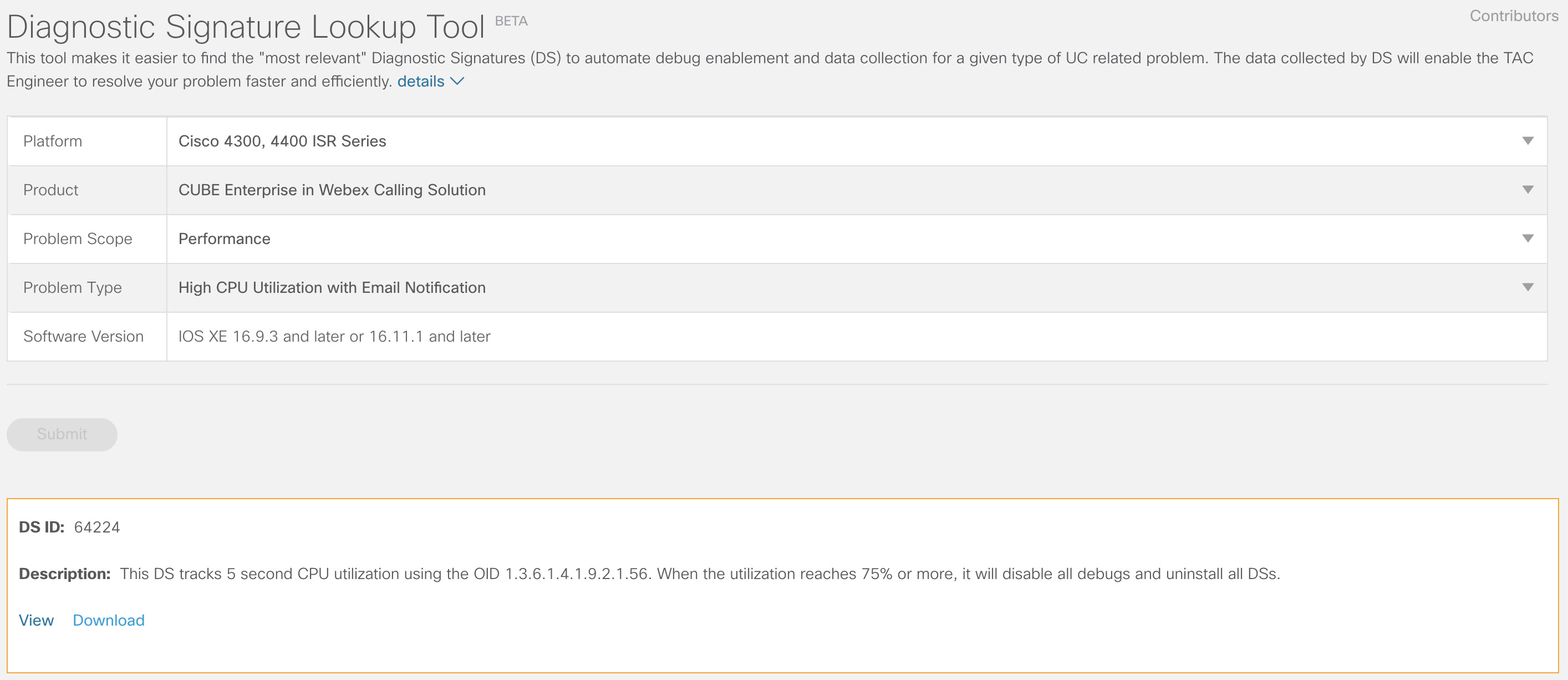
DS זה עוקב אחר ניצול המעבד במשך חמש שניות באמצעות SNMP OID 1.3.6.1.4.1.9.2.1.56. כאשר ניצול המערכת מגיע ל-75% או יותר, היא מבטלת את כל ניפויי הבאגים ומסירה את ההתקנה של כל חתימות האבחון המותקנות בשער המקומי. השתמש בשלבים הבאים כדי להתקין את החתימה.
-
השתמש בפקודה show snmp כדי להפעיל את SNMP. אם לא תפעיל, הגדר את הפקודה snmp-server manager.
show snmp %SNMP agent not enabled config t snmp-server manager end show snmp Chassis: ABCDEFGHIGK 149655 SNMP packets input 0 Bad SNMP version errors 1 Unknown community name 0 Illegal operation for community name supplied 0 Encoding errors 37763 Number of requested variables 2 Number of altered variables 34560 Get-request PDUs 138 Get-next PDUs 2 Set-request PDUs 0 Input queue packet drops (Maximum queue size 1000) 158277 SNMP packets output 0 Too big errors (Maximum packet size 1500) 20 No such name errors 0 Bad values errors 0 General errors 7998 Response PDUs 10280 Trap PDUs Packets currently in SNMP process input queue: 0 SNMP global trap: enabled -
הורד את DS 64224 באמצעות אפשרויות הרשימה הנפתחת הבאות ב-Diagnostic Signatures Lookup Tool:
שם שדה
ערך שדה
פלטפורמה
סדרת סיסקו 4300, 4400 ISR או סדרת סיסקו CSR 1000V
מוצר
CUBE Enterprise בפתרון Webex Calling
היקף בעיה
ביצועים
סוג בעיה
ניצול מעבד גבוה עם התראות דוא"ל.
-
העתק את קובץ ה-XML של DS ל-flash של השער המקומי.
LocalGateway# copy ftp://username:password@/DS_64224.xml bootflash:הדוגמה הבאה מציגה העתקת הקובץ משרת FTP לשער המקומי.
copy ftp://user:pwd@192.0.2.12/DS_64224.xml bootflash: Accessing ftp://*:*@ 192.0.2.12/DS_64224.xml...! [OK - 3571/4096 bytes] 3571 bytes copied in 0.064 secs (55797 bytes/sec) -
התקן את קובץ ה-XML של DS בשער המקומי.
call-home diagnostic-signature load DS_64224.xml Load file DS_64224.xml success -
השתמש בפקודה show call-home diagnostic-signature כדי לוודא שהחתימה הותקנה בהצלחה. עמודת המצב צריכה לכלול ערך "רשום".
show call-home diagnostic-signature
Current diagnostic-signature settings:
Diagnostic-signature: enabled
Profile: CiscoTAC-1 (status: ACTIVE)
Downloading  URL(s):  https://tools.cisco.com/its/service/oddce/services/DDCEService
Environment variable:
ds_email: username@gmail.com
הורד חתימות DS:
מזהה DS
שם DC
מהדורה
מצב
עדכון אחרון (GMT+00:00)
64224
DS_LGW_CPU_MON75
0.0.10
רשום
2020-11-07 22:05:33
כאשר החתימה הזו מופעלת, היא מסירה את ההתקנה של כל חתימות האבחון הפועלות, כולל את עצמה. במידת הצורך, התקן מחדש את DS 64224 כדי להמשיך לנטר ניצול CPU גבוה ב-Local Gateway.
ניטור רישום SIP trunk
DS זה בודק אי-רישום של שער מקומי של SIP Trunk עם Webex Calling Cloud כל 60 שניות. לאחר זיהוי אירוע ביטול הרישום, המערכת יוצרת הודעת דוא"ל ויומן מערכת ומסירה את ההתקנה שלה לאחר שני אירועי ביטול רישום. בצע את השלבים הבאים כדי להתקין את החתימה:
-
הורד את DS 64117 באמצעות אפשרויות הרשימה הנפתחת הבאות ב-Diagnostic Signatures Lookup Tool:
שם שדה
ערך שדה
פלטפורמה
Cisco 4300, 4400 ISR Series או Cisco CSR 1000V Series
מוצר
CUBE Enterprise בפתרון Webex Calling
היקף בעיה
SIP-SIP
סוג בעיה
ביטול רישום של SIP Trunk עם הודעת דוא"ל.
-
העתק את קובץ ה-XML של DS לשער המקומי.
copy ftp://username:password@/DS_64117.xml bootflash: -
התקן את קובץ ה-XML של DS בשער המקומי.
call-home diagnostic-signature load DS_64117.xml Load file DS_64117.xml success LocalGateway# -
השתמש בפקודה show call-home diagnostic-signature כדי לוודא שהחתימה הותקנה בהצלחה. עמודת הסטטוס חייבת להכיל ערך "רשום".
ניטור ניתוקי שיחות חריגים
מערכת DS זו משתמשת בבדיקת SNMP כל 10 דקות כדי לזהות ניתוק שיחה חריג עם שגיאות SIP 403, 488 ו-503. אם תוספת ספירת השגיאות גדולה או שווה ל-5 מהבדיקה האחרונה, היא מייצרת הודעה על יומן מערכת (syslog) והודעת דוא"ל. אנא בצע את השלבים הבאים כדי להתקין את החתימה.
-
השתמש בפקודה show snmp כדי לבדוק אם SNMP מופעל. אם הוא אינו מופעל, הגדר את הפקודה snmp-server manager.
show snmp %SNMP agent not enabled config t snmp-server manager end show snmp Chassis: ABCDEFGHIGK 149655 SNMP packets input 0 Bad SNMP version errors 1 Unknown community name 0 Illegal operation for community name supplied 0 Encoding errors 37763 Number of requested variables 2 Number of altered variables 34560 Get-request PDUs 138 Get-next PDUs 2 Set-request PDUs 0 Input queue packet drops (Maximum queue size 1000) 158277 SNMP packets output 0 Too big errors (Maximum packet size 1500) 20 No such name errors 0 Bad values errors 0 General errors 7998 Response PDUs 10280 Trap PDUs Packets currently in SNMP process input queue: 0 SNMP global trap: enabled -
הורד את DS 65221 באמצעות האפשרויות הבאות ב-Diagnostic Signatures Lookup Tool:
שם שדה
ערך שדה
פלטפורמה
Cisco 4300, 4400 ISR Series או Cisco CSR 1000V Series
מוצר
CUBE Enterprise בפתרון Webex Calling
היקף בעיה
ביצועים
סוג בעיה
זיהוי ניתוק שיחה חריג ב-SIP באמצעות התראות דוא"ל ו-Syslog.
-
העתק את קובץ ה-XML של DS לשער המקומי.
copy ftp://username:password@/DS_65221.xml bootflash: -
התקן את קובץ ה-XML של DS בשער המקומי.
call-home diagnostic-signature load DS_65221.xml Load file DS_65221.xml success -
השתמש בפקודה show call-home diagnostic-signature כדי לוודא שהחתימה הותקנה בהצלחה. עמודת הסטטוס חייבת להכיל ערך "רשום".
התקנת חתימות אבחון כדי לפתור בעיה
השתמש בחתימות אבחון (DS) כדי לפתור בעיות במהירות. מהנדסי Cisco TAC כתבו מספר חתימות המאפשרות את ניפוי הבאגים הדרושים לפתרון בעיות נתונות, זיהוי התרחשות הבעיה, איסוף נתוני האבחון הנכונים והעברת הנתונים באופן אוטומטי למארז Cisco TAC. חתימות אבחון (DS) מבטלות את הצורך לבדוק ידנית את התרחשות הבעיה ומקלות מאוד על פתרון בעיות לסירוגין וחולפות.
ניתן להשתמש בכלי Diagnostic Signatures Lookup Tool כדי למצוא את החתימות הרלוונטיות ולהתקין אותן כדי לפתור בעיה נתונה באופן עצמאי, או להתקין את החתימה המומלצת על ידי מהנדס TAC כחלק מהתקשרות התמיכה.
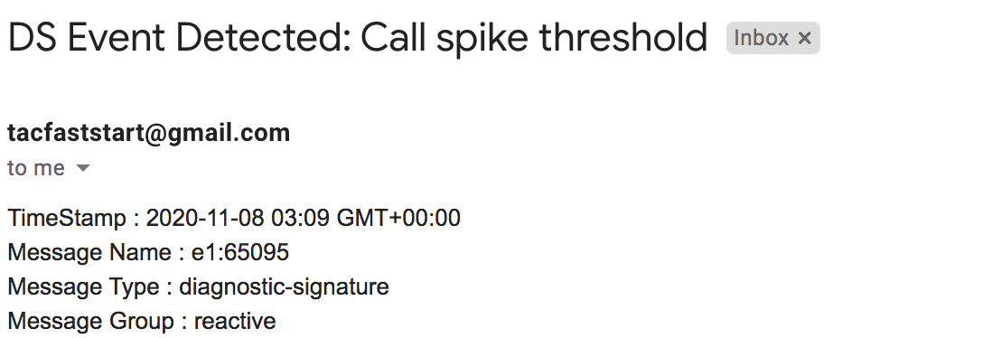
הנה דוגמה כיצד למצוא ולהתקין DS כדי לזהות את המופע "%VOICE_IEC-3-GW: CCAPI: Internal Error (call spike threshold): IEC=1.1.181.1.29.0" syslog ואוטומציה של איסוף נתוני אבחון באמצעות השלבים הבאים:
-
הגדר משתנה סביבה נוסף של DS ds_fsurl_prefixשהוא נתיב שרת הקבצים של Cisco TAC (cxd.cisco.com) שאליו מועלים נתוני האבחון שנאספו. שם המשתמש בנתיב הקובץ הוא מספר המקרה והסיסמה היא אסימון העלאת הקובץ שניתן לאחזר מ- Support Case Manager בפקודה הבאה. ניתן ליצור את אסימון העלאת הקובץ במקטע Attachments של Support Case Manager, לפי הצורך.
configure terminal
call-home
diagnostic-signature
LocalGateway(cfg-call-home-diag-sign)environment ds_fsurl_prefix "scp://:@cxd.cisco.com"
end
דוגמה:
call-home diagnostic-signature environment ds_fsurl_prefix " environment ds_fsurl_prefix "scp://612345678:abcdefghijklmnop@cxd.cisco.com" -
ודא ש-SNMP מופעל באמצעות הפקודה show snmp. אם הוא אינו מופעל, הגדר את הפקודה snmp-server manager.
show snmp %SNMP agent not enabled config t snmp-server manager end -
ודא להתקין את ניטור ה-High CPU DS 64224 כאמצעי יזום להשבתת כל ניפויי הבאגים וחתימות האבחון בזמן ניצול CPU גבוה. הורד את DS 64224 באמצעות האפשרויות הבאות ב-Diagnostic Signatures Lookup Tool:
שם שדה
ערך שדה
פלטפורמה
Cisco 4300, 4400 ISR Series או Cisco CSR 1000V Series
מוצר
CUBE Enterprise בפתרון Webex Calling
היקף בעיה
ביצועים
סוג בעיה
ניצול מעבד גבוה עם התראות דוא"ל.
-
הורד את DS 65095 באמצעות האפשרויות הבאות ב-Diagnostic Signatures Lookup Tool:
שם שדה
ערך שדה
פלטפורמה
Cisco 4300, 4400 ISR Series או Cisco CSR 1000V Series
מוצר
CUBE Enterprise בפתרון Webex Calling
היקף בעיה
יומני Syslog
סוג בעיה
Syslog - %VOICE_IEC-3-GW: CCAPI: Internal Error (Call spike threshold): IEC=1.1.181.1.29.0
-
העתק את קובצי ה-XML של DS לשער המקומי.
copy ftp://username:password@/DS_64224.xml bootflash: copy ftp://username:password@/DS_65095.xml bootflash: -
התקן את קובץ ה-XML של DS 64224 לניטור ניצול גבוה של CPU ולאחר מכן את קובץ ה-XML של DS 65095 בשער המקומי.
call-home diagnostic-signature load DS_64224.xml Load file DS_64224.xml success call-home diagnostic-signature load DS_65095.xml Load file DS_65095.xml success -
ודא שהחתימה הותקנה בהצלחה באמצעות הפקודה show call-home diagnostic-signature. עמודת הסטטוס חייבת להכיל ערך "רשום".
show call-home diagnostic-signature
Current diagnostic-signature settings:
Diagnostic-signature: enabled
Profile: CiscoTAC-1 (status: ACTIVE)
Downloading  URL(s):  https://tools.cisco.com/its/service/oddce/services/DDCEService
Environment variable:
           ds_email: username@gmail.com
           ds_fsurl_prefix: scp://612345678:abcdefghijklmnop@cxd.cisco.com
חתימות DS שהורדו:
מזהה DS
שם DC
מהדורה
מצב
עדכון אחרון (GMT+00:00)
64224
00:07:45
DS_LGW_CPU_MON75
0.0.10
רשום
2020-11-08
65095
00:12:53
DS_LGW_IEC_Call_spike_threshold
0.0.12
רשום
2020-11-08
אימות ביצוע חתימות אבחון
בפקודה הבאה, עמודת "Status" של הפקודה show call-home diagnostic-signature משתנה ל-"running" בזמן שה-Local Gateway מבצע את הפעולה שהוגדרה בחתימה. הפלט של show call-home diagnostic-signature statistics הוא הדרך הטובה ביותר לוודא האם חתימת אבחון מזהה אירוע מעניין ומבצעת את הפעולה. ה “Triggered/Max/Deinstall” העמודה מציינת את מספר הפעמים שהחתימה הנתונה הפעילה אירוע, את מספר הפעמים המרבי שהיא מוגדרת לזהות אירוע, והאם החתימה מסירה את עצמה לאחר זיהוי המספר המרבי של אירועים שהופעלו.
show call-home diagnostic-signature
Current diagnostic-signature settings:
Diagnostic-signature: enabled
Profile: CiscoTAC-1 (status: ACTIVE)
Downloading  URL(s):  https://tools.cisco.com/its/service/oddce/services/DDCEService
Environment variable:
           ds_email: carunach@cisco.com
           ds_fsurl_prefix: scp://612345678:abcdefghijklmnop@cxd.cisco.com
חתימות DS שהורדו:
|
מזהה DS |
שם DC |
מהדורה |
מצב |
עדכון אחרון (GMT+00:00) |
|---|---|---|---|---|
| 64224 |
DS_LGW_CPU_MON75 |
0.0.10 |
רשום |
2020-11-08 00:07:45 |
|
65095 |
DS_LGW_IEC_Call_spike_threshold |
0.0.12 |
פועל |
2020-11-08 00:12:53 |
הצגת סטטיסטיקות של חתימות אבחון של שיחות טלפון ביתיות
|
מזהה DS |
שם DC |
הופעל/Max/Deinstall |
זמן ריצה ממוצע (שניות) |
זמן ריצה מקסימלי (שניות) |
|---|---|---|---|---|
| 64224 |
DS_LGW_CPU_MON75 |
0/0/N |
0.000 |
0.000 |
|
65095 |
DS_LGW_IEC_Call_spike_threshold |
1/20/Y |
23.053 |
23.053 |
דוא"ל ההתראה שנשלח במהלך ביצוע חתימת אבחון מכיל מידע מפתח כגון סוג הבעיה, פרטי המכשיר, גרסת התוכנה, תצורת ההפעלה, והצגת פלטי פקודות הרלוונטיים לפתרון בעיות הבעיה הנתונה.
הסרת ההתקנה של חתימות אבחון
שימוש בחתימות אבחון למטרות פתרון בעיות מוגדר בדרך כלל להסרת התקנה לאחר זיהוי של מופעי בעיה מסוימים. אם ברצונך להסיר חתימה באופן ידני, אחזר את מזהה ה-DS מהפלט של הפקודה show call-home diagnostic-signature והרץ את הפקודה הבאה:
call-home diagnostic-signature deinstall
דוגמה:
call-home diagnostic-signature deinstall 64224
חתימות חדשות מתווספות לכלי חיפוש חתימות האבחון מעת לעת, בהתבסס על בעיות שנצפות בדרך כלל בפריסות. TAC אינו תומך כרגע בבקשות ליצירת חתימות מותאמות אישית חדשות.
לניהול טוב יותר של שערי Cisco IOS XE, אנו ממליצים לרשום ולנהל את השערים דרך מרכז הבקרה. זוהי תצורה אופציונלית. לאחר ההרשמה, באפשרותך להשתמש באפשרות אימות התצורה במרכז הבקרה כדי לאמת את תצורת השער המקומי שלך ולזהות בעיות תצורה. נכון לעכשיו, רק trunks מבוססי רישום תומכים בפונקציונליות זו.
למידע נוסף, עיינו במידע הבא:
סעיף זה מתאר כיצד להגדיר אלמנט גבול מאוחד של Cisco (CUBE) כשער מקומי עבור Webex Calling באמצעות רשת TLS (mTLS) הדדית מבוססת אישורים. החלק הראשון של מסמך זה ממחיש כיצד להגדיר שער PSTN פשוט. במקרה זה, כל השיחות מה-PSTN מנותבות ל-Webex Calling וכל השיחות מ-Webex Calling מנותבות ל-PSTN. התמונה הבאה מדגישה פתרון זה ואת תצורת ניתוב השיחות ברמה גבוהה שתתבצע.
בתכנון זה, נעשה שימוש בתצורות העיקריות הבאות:
-
דיירים בכיתת קול: Used כדי ליצור תצורות ספציפיות לתא המטען.
-
URI של מחלקת קול: משמש לסיווג הודעות SIP לבחירת עמית לחיוג נכנס.
-
עמית חיוג נכנס: מספק טיפול בהודעות SIP נכנסות וקובע את הנתיב היוצא באמצעות קבוצת חיוג-עמית.
-
קבוצת עמיתים לחיוג: מגדיר את עמיתי החיוג היוצא המשמשים לניתוב שיחות קדימה.
-
עמית חיוג יוצא: מספק טיפול בהודעות SIP יוצאות ונותב אותן ליעד הנדרש.
בעת חיבור פתרון Cisco Unified Communications Manager מקומי עם Webex Calling, ניתן להשתמש בתצורת שער PSTN פשוטה כבסיס לבניית הפתרון המוצג בתרשים הבא. במקרה זה, מנהל תקשורת מאוחד מספק ניתוב וטיפול מרכזיים בכל שיחות PSTN ו-Webex Calling.
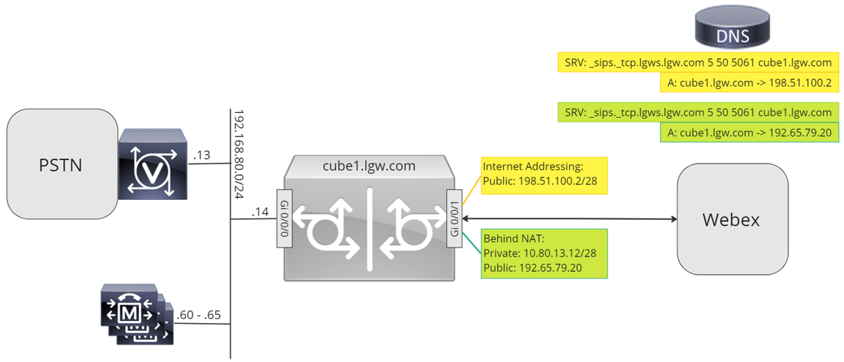
לאורך מסמך זה, נעשה שימוש בשמות המארחים, כתובות ה-IP והממשקים המוצגים בתמונה הבאה. ניתנות אפשרויות לכתובת ציבורית או פרטית (מאחורי NAT). רשומות DNS של SRV הן אופציונליות, אלא אם כן מדובר באיזון עומסים על פני מספר מופעי CUBE.
השתמש בהנחיות התצורה בשאר מסמך זה כדי להשלים את תצורת השער המקומי שלך באופן הבא:
תצורת בסיס
השלב הראשון בהכנת נתב Cisco שלך כשער מקומי עבור Webex Calling הוא בניית תצורה בסיסית שמאבטחת את הפלטפורמה שלך ומבססת קישוריות.
-
כל פריסות ה-Local Gateway המבוססות על אישורים דורשות Cisco IOS XE 17.9.1a או גרסאות מאוחרות יותר. מומלץ להשתמש ב-Cisco IOS XE 17.12.2 או גרסה מתקדמת יותר. לגרסאות המומלצות, עיינו בדף Cisco Software Research. חפש את הפלטפורמה ובחר אחת מהגרסאות המוצעות.
-
נתבים מסדרת ISR4000 חייבים להיות מוגדרים עם רישיונות טכנולוגיית תקשורת מאוחדת (Unified Communications) ורישיונות טכנולוגיית אבטחה (Security).
-
נתבים מסדרת Catalyst Edge 8000 המצוידים בכרטיסי קול או מערכות זיהוי דיגיטליות (DSP) דורשים רישיון DNA Advantage. נתבים ללא כרטיסי קול או מערכות זיהוי דיגיטליות (DSP) דורשים רישיון DNA Essentials לפחות.
-
עבור דרישות קיבולת גבוהה, ייתכן שתזדקק גם לרישיון אבטחה גבוהה (HSEC) ולהרשאות תפוקה נוספות.
עיין ב- קודי אישור לפרטים נוספים.
-
-
בנה תצורת בסיס לפלטפורמה שלך שתתאים למדיניות העסקית שלך. בפרט, יש להגדיר ולאמת את הדברים הבאים:
-
NTP
-
רשימות בקרת גישה (ACL)
-
אימות משתמש וגישה מרחוק
-
DNS
-
ניתוב IP
-
כתובות IP
-
-
הרשת ל-Webex Calling חייבת להשתמש בכתובת IPv4. כתובות של שמות מתחם מלאים (FQDN) או רשומת שירות (SRV) של שער מקומי שתצורתן נקבעה במרכז הבקרה חייבות להיקרא כתובת IPv4 ציבורית באינטרנט.
-
כל יציאות ה-SIP והמדיה בממשק השער המקומי הפונה ל-Webex חייבות להיות נגישות מהאינטרנט, ישירות או דרך NAT סטטי. ודא שאתה מעדכן את חומת האש שלך בהתאם.
-
בצע את שלבי התצורה המפורטים המופיעים להלן כדי להתקין אישור חתום בשער המקומי:
-
רשות אישורים ציבורית (CA) כמפורט ב- אילו רשויות אישורים בסיסיות נתמכות עבור קריאות לפלטפורמות שמע ווידאו של Cisco Webex? חייבת לחתום על אישור המכשיר.
-
אישורים המכילים רק שימוש מורחב במפתחות של אימות שרת (EKU) נתמכים. Webex Calling אינו מאמת או אוכף את נוכחותו של EKU לאימות לקוח במהלך יצירת לחיצת יד של TLS.
ייתכן שחלק מבקרי גבולות ההפעלה (SBC) של צד שלישי יאכוף אימות EKU קפדני ולדחות אישורים שאינם כוללים EKU לאימות לקוח. במקרים כאלה, ודא ש-SBC מוגדר לקבל אישורים עם אימות שרת EKU בלבד או להשבית אימות EKU קפדני (אם נתמך).
-
השם המשותף (CN) של נושא האישור, או אחד משמות החלופיים של הנושא (SAN), חייב להיות זהה ל-FQDN שתצורתו נקבעה במרכז הבקרה.
בעת רכישת תעודה עם שם נפוץ (CN) או שם חלופי לנושא (SAN), יש לוודא שהתעודה משתמשת באותיות קטנות בלבד. בתצורת Control Hub, כל ערכי ה-FQDN מומרים אוטומטית לאותיות קטנות, וכל אי התאמה באותיות גדולות וקטנות בין ה-FQDN לאישור תמנע רישום מוצלח של trunk.
לדוגמה:
-
אם יש trunk שתצורתו נקבעה במרכז הבקרה של הארגון שלך cube1.lgw.com:5061 כ-FQDN של השער המקומי, אז ה-CN או ה-SAN בתעודת הנתב חייבים להכיל cube1.lgw.com.
-
אם כתובת ה-SRV של שער מקומי (Local Gateway) אליהם ניתן להגיע מהתאנק (trunk) מוגדרת במרכז הבקרה של הארגון שלך היא lgws.lgw.com, אז ה-CN או ה-SAN בתעודת הנתב חייבים להכיל lgws.lgw.com. הרשומות שכתובת ה-SRV מפוענחת אליהן (CNAME, רשומת A או כתובת IP) הן אופציונליות ב-SAN.
-
בין אם אתה משתמש ב-FQDN או ב-SRV עבור ה-trunk, כתובת איש הקשר עבור כל דיאלוגי SIP חדשים מהשער המקומי שלך חייבת להשתמש בשם שתצורתו נקבעה במרכז הבקרה.
-
-
-
העלה את חבילת רשות האישורים הבסיסית של Cisco לשער המקומי. חבילה זו כוללת את אישור הבסיס של רשות האישור המשמש לאימות פלטפורמת Webex.
הגדרת תצורה
| 1 |
צור תא מטען PSTN מבוסס אישור CUBE עבור מיקום קיים במרכז הבקרה. למידע נוסף, ראה הגדרת רשתות גז, קבוצות ניתוב ותוכניות חיוג עבור Webex Calling. רשום לעצמך את פרטי תא המטען בעת יצירת תא המטען. פרטים אלה, כפי שמוצגים באיור הבא, משמשים בשלבי התצורה במדריך זה.
|
| 2 |
הזן את הפקודות הבאות כדי להגדיר את CUBE כשער מקומי של Webex Calling: הנה הסבר על השדות עבור התצורה:
מאפשר תכונות של Cisco Unified Border Element (CUBE) בפלטפורמה. אפשר חיבורים בין סימפוניםהפעל פונקציונליות סוכן משתמש בסיסי של SIP גב אל גב של CUBE. למידע נוסף, ראה אפשר חיבורים. כברירת מחדל, העברת פקס T.38 מופעלת. למידע נוסף, ראה פרוטוקול פקס t38 (שירות קולי). מאפשר STUN (Session Traversal of UDP through NAT) באופן גלובלי. פקודות הלם גלובליות אלו נדרשות רק בעת פריסת השער המקומי שלך מאחורי NAT.
למידע נוסף, ראו stun flowdata agent-idו- stun flowdata shared-secret. מטען אסימטרי מלאמגדיר תמיכה במטענים אסימטריים של SIP עבור טעינות DTMF ו-codec דינמי. למידע נוסף על פקודה זו, ראו מטען אסימטרי. הצעה מוקדמת כפויהמאלץ את השער המקומי לשלוח מידע SDP בהודעת ה-INVITE הראשונית במקום להמתין לאישור מהעמית השכן. למידע נוסף על פקודה זו, ראו הצעה מוקדמת. פרופילי SIP נכנסיםמאפשר ל-CUBE להשתמש בפרופילי SIP כדי לשנות הודעות עם קבלתן. פרופילים מוחלים באמצעות עמיתים בחיוג או דיירים. |
| 3 |
הגדר קודק מחלקת קול 100 המאפשר קודקים של G.711 עבור כל ה-trunks בלבד. גישה פשוטה זו מתאימה לרוב הפריסות. במידת הצורך, הוסף לרשימה סוגי קודקים נוספים הנתמכים על ידי מערכות המקור והסיום כאחד. פתרונות מורכבים יותר הכוללים קידוד מחדש באמצעות מודולי DSP נתמכים, אך אינם כלולים במדריך זה. הנה הסבר על השדות עבור התצורה: קודק של מחלקת קול 100משמש כדי לאפשר רק קודקים מועדפים עבור שיחות SIP trunk. למידע נוסף, ראו קודק מחלקת קול. |
| 4 |
הגדר את voice class stun-usage 100 כדי להפעיל ICE ב-Webex Calling trunk. (שלב זה אינו רלוונטי עבור Webex לממשל) הנה הסבר על השדות עבור התצורה: שימוש בהלם בקרח לייטמשמש להפעלת ICE-Lite עבור כל עמיתים לחיוג הפונים ל-Webex Calling כדי לאפשר אופטימיזציה של מדיה במידת האפשר. למידע נוסף, ראו שימוש בהלם ברמת קול ו- שימוש בהלם ברמת קרח לייט. הפקודהstun usage firewall-traversal flowdataנדרשת רק בעת פריסת השער המקומי שלך מאחורי NAT. אופטימיזציה של המדיה נערכת במשא ומתן במידת האפשר. אם שיחה דורשת שירותי מדיה בענן, כגון הקלטה, לא ניתן לבצע אופטימיזציה של המדיה. |
| 5 |
הגדר את מדיניות הצפנת המדיה עבור תעבורת Webex. (שלב זה אינו רלוונטי עבור Webex לממשל) הנה הסבר על השדות עבור התצורה: מחלקת קול srtp-crypto 100מציין את SHA1_80 כהצעות CUBE היחידות של חבילת הצפנת SRTP ב-SDP בהודעות הצעה ותשובה. שיחות Webex תומכות רק ב-SHA1_80. למידע נוסף, ראה מחלקת קול srtp-crypto. |
| 6 |
קבע את תצורת צפני GCM תואמי FIPS (שלב זה חל רק על Webex לממשל). הנה הסבר על השדות עבור התצורה: מחלקת קול srtp-crypto 100מציין את GCM כחבילת ההצפנה שמציעה CUBE. חובה להגדיר צפני GCM עבור Local Gateway עבור Webex for Government. |
| 7 |
הגדר תבנית לזיהוי ייחודי של קריאות ל- Local Gateway trunk בהתבסס על FQDN או SRV היעד שלו: הנה הסבר על השדות עבור התצורה: קול מחלקה URI 100 sipמגדיר תבנית להתאמה של הזמנת SIP נכנסת לעמית חיוג trunk נכנס. בעת הזנת תבנית זו, השתמש ב-FQDN או ב-SRV של ה-trunk שתצורתם נקבעה במרכז הבקרה עבור ה-trunk. במהלך קביעת תצורה בצד הדייר של trunks מבוססי אישורים עבור Webex Calling, השתמש רק בכתובת Webex Calling Edge מבוססת SRV בשער המקומי. כתובות FQDN אינן נתמכות עוד. |
| 8 |
קבע את תצורת פרופילי מניפולציה של הודעות SIP. אם השער שלך מוגדר עם כתובת IP ציבורית, הגדר פרופיל באופן הבא או דלג לשלב הבא אם אתה משתמש ב-NAT. בדוגמה זו, cube1.lgw.com הוא ה-FQDN שתצורתו נקבעה עבור השער המקומי: הנה הסבר על השדות עבור התצורה: כללים 10 ו-20כדי לאפשר ל-Webex לאמת הודעות מהשער המקומי שלך, הכותרת 'איש קשר' בהודעות בקשת SIP ותגובות חייבת להכיל את הערך שהוקצה עבור ה-trunk במרכז הבקרה. זה יהיה ה-FQDN של מארח יחיד, או שם ה-SRV המשמש עבור אשכול של התקנים. |
| 9 |
אם השער שלך מוגדר עם כתובת IP פרטית מאחורי NAT סטטי, הגדר את פרופילי ה-SIP הנכנסים והיוצאים באופן הבא. בדוגמה זו, cube1.lgw.com הוא ה-FQDN שתצורתו נקבעה עבור השער המקומי, "10.80.13.12" היא כתובת ה-IP של הממשק הפונה ל-Webex Calling ו-"192.65.79.20" היא כתובת ה-IP הציבורית של NAT. פרופילי SIP עבור הודעות יוצאות ל-Webex Calling
הנה הסבר על השדות עבור התצורה: כללים 10 ו-20כדי לאפשר ל-Webex לאמת הודעות מהשער המקומי שלך, הכותרת 'איש קשר' בהודעות בקשות ותגובות של SIP חייבת להכיל את הערך שהוקצה עבור ה-trunk במרכז הבקרה. זה יהיה ה-FQDN של מארח יחיד, או שם ה-SRV המשמש עבור אשכול של התקנים. כללים 30 עד 81המר הפניות לכתובות פרטיות לכתובת הציבורית החיצונית של האתר, מה שמאפשר ל-Webex לפרש ולנתב נכון הודעות עוקבות. פרופיל SIP עבור הודעות נכנסות מ-Webex Callingהנה הסבר על השדות עבור התצורה: כללים 10 עד 80המר הפניות לכתובת ציבורית לכתובת הפרטית שתצורתה נקבעה, מה שמאפשר ל-CUBE לעבד את ההודעות מ-Webex. למידע נוסף, ראו פרופילי SIP של מחלקת קול. ספק שירותי PSTN בארצות הברית או בקנדה יכול להציע אימות זיהוי מתקשר עבור שיחות ספאם והונאה, עם התצורה הנוספת המוזכרת במאמר אינדיקציה של שיחת ספאם או הונאה ב-Webex Calling. |
| 10 |
הגדר פרופיל שינוי כותרת של אפשרויות SIP שנשמרות בזמן אמת.
|
| 11 |
הגדרת רשת שיחות Webex: |
| 12 |
(אופציונלי) כדי להגדיר התקני רשת כגון CUBE ולהעביר כותרות של Session Initiation Protocol (SIP) שההתקן אינו מעבד, השתמש בפקודות אלה. פקודות אלה מאפשרות למכשיר להעביר דרך כותרות SIP שאינן נתמכות, כולל כותרות מיקום גיאוגרפי ו-PIDF-LO (פורמט נתוני מידע נוכחות - אובייקט מיקום), בשער המקומי. פונקציונליות זו תומכת בשירותי Nomadic E-911 על ידי הבטחת שמירה והעברת מידע קריטי על מיקום בצורה נכונה. |
לאחר שבניתם trunk (תא מטען) לכיוון Webex Calling לעיל, השתמשו בתצורה הבאה כדי ליצור trunk לא מוצפן לכיוון ספק PSTN מבוסס SIP:
אם ספק השירות שלך מציע רשת PSTN מאובטחת, תוכל לבצע תצורה דומה לזו המפורטת לעיל עבור רשת Webex Calling. CUBE תומך בניתוב שיחות מאובטח.
אם אתה משתמש ב-TDM / IPS (ISDN PSTN trunk), דלג לסעיף הבא הגדרת שער מקומי עם TDM PSTN trunk.
כדי להגדיר ממשקי TDM עבור רגלי שיחות PSTN בשערי Cisco TDM-SIP, ראה הגדרת ISDN PRI.
| 1 |
הגדר את ה-uri של מחלקת הקול הבאה כדי לזהות שיחות נכנסות מרשת ה-PSTN: הנה הסבר על השדות עבור התצורה: קול מחלקה URI 200 sipמגדיר תבנית להתאמה של הזמנת SIP נכנסת לעמית חיוג trunk נכנס. בעת הזנת תבנית זו, השתמש בכתובת ה-IP של שער ה-IP PSTN שלך. למידע נוסף, ראו uri של מחלקת קול. |
| 2 |
הגדר את עמית החיוג הבא של IP PSTN: הנה הסבר על השדות עבור התצורה: מגדיר עמית חיוג VoIP עם תגית 200 ומספק תיאור משמעותי לנוחות הניהול ופתרון בעיות. למידע נוסף, ראו קול חיוג-עמית. תבנית-יעד גרועה.גרועהנדרשת תבנית יעד דמה בעת ניתוב שיחות יוצאות באמצעות קבוצת עמיתים לחיוג נכנס. במקרה זה ניתן להשתמש בכל תבנית יעד תקפה. למידע נוסף, ראו destination-pattern (ממשק). פרוטוקול הפעלה sipv2מציין שעמית חיוג זה מטפל ברגלי שיחות SIP. למידע נוסף, ראה פרוטוקול סשן (חיוג עמית). יעד סשן ipv4: 192.168.80.13מציין את כתובת היעד עבור שיחות הנשלחות לספק PSTN. זה יכול להיות כתובת IP או שם מארח DNS. למידע נוסף, ראה יעד סשן (עמית חיוג VoIP). URI נכנס דרך 200מציין את מחלקת הקול המשמשת להתאמת שיחות נכנסות לעמית חיוג זה באמצעות URI הכותרת INVITE VIA. למידע נוסף, ראה כתובת URL נכנסת. קול-מחלקה sip asserted-id pai
(אופציונלי) מפעיל את עיבוד כותרת P-Asserted-Identity ושולט באופן השימוש בו עבור trunk PSTN. אם משתמשים בפקודה זו, זהות הצד המתקשר שסופקה על ידי עמית החיוג הנכנס תשמש עבור כותרות ה-From וה-P-Asserted-Identity היוצאות. אם פקודה זו אינה בשימוש, זהות הצד הקורא המסופקת על ידי עמית החיוג הנכנס תשמש עבור כותרות ה-From ו-Remote-Party-ID היוצאות. למידע נוסף, ראה voice-class sip asserted-id. ממשק מקור-בקרת קשירה GigabitEthernet0/0/0
מגדיר את ממשק המקור ואת כתובת ה-IP המשויכת להודעות הנשלחות ל-PSTN. למידע נוסף, ראה bind. קשירת ממשק מקור מדיה GigabitEthernet0/0/0מגדיר את ממשק המקור ואת כתובת ה-IP המשויכת למדיה הנשלחת ל-PSTN. למידע נוסף, ראה bind. קודק מסוג קול 100מגדיר את עמית החיוג לשימוש ברשימת מסנני הקודקים המשותפים 100. למידע נוסף, ראו קודק מסוג קול. dtmf-relay rtp-nteמגדיר RTP-NTE (RFC2833) כיכולת DTMF הצפויה ברגל השיחה. למידע נוסף, ראה DTMF Relay (קול מעל IP). אין וואדיםמשבית את זיהוי הפעילות הקולית. למידע נוסף, ראה vad (חיוג עמית). |
| 3 |
אם אתה מגדיר את השער המקומי שלך לניתוב שיחות רק בין Webex Calling ל-PSTN, הוסף את תצורת ניתוב השיחות הבאה. אם אתם מגדירים את ה-Local Gateway שלכם עם פלטפורמת Unified Communications Manager, דלגו לסעיף הבא. |
לאחר שבניתם trunk עבור Webex Calling, השתמשו בתצורה הבאה כדי ליצור trunk TDM עבור שירות PSTN שלכם עם ניתוב שיחות בלולאה חזרה כדי לאפשר אופטימיזציה של מדיה ברגל שיחת Webex.
אם אינך זקוק לאופטימיזציה של מדיה IP, בצע את שלבי התצורה עבור trunk של SIP PSTN. השתמש ביציאת קול ועמית חיוג POTS (כפי שמוצג בשלבים 2 ו-3) במקום עמית חיוג VoIP של PSTN.
| 1 |
תצורת חיוג-עמית בלולאה חזרה משתמשת בקבוצות חיוג-עמית ותגי ניתוב שיחות כדי להבטיח ששיחות יעברו כראוי בין Webex ל-PSTN, מבלי ליצור לולאות ניתוב שיחות. הגדר את כללי התרגום הבאים שישמשו להוספה והסרה של תגי ניתוב שיחות: הנה הסבר על השדות עבור התצורה: כלל תרגום קולימשתמש בביטויים רגולריים המוגדרים בכללים כדי להוסיף או להסיר תגי ניתוב שיחות. ספרות מעל עשרוניות ('A') משמשות להוספת בהירות לפתרון בעיות. בתצורה זו, התג שנוסף על ידי פרופיל התרגום 100 משמש להכוונת שיחות מ-Webex Calling אל ה-PSTN דרך עמיתים לחיוג לולאה חוזר. באופן דומה, התג שנוסף על ידי פרופיל התרגום 200 משמש להכוונת שיחות מה-PSTN לכיוון Webex Calling. פרופילי תרגום 11 ו-12 מסירים תגים אלה לפני העברת שיחות לרשתות Webex ו-PSTN בהתאמה. דוגמה זו מניחה שמספרים שאליהם התקשרו מ-Webex Calling מוצגים ב +E.164 פוּרמָט. כלל 100 מסיר את הכותרת המובילה + כדי לשמור על מספר טלפון תקין. כלל 12 מוסיף לאחר מכן ספרת/ות ניתוב לאומית או בינלאומית בעת הסרת התג. השתמש בספרות שמתאימות לתוכנית החיוג הארצית של ISDN שלך. אם Webex Calling מציג מספרים בפורמט ארצי, יש להתאים את הכללים 100 ו-12 כדי להוסיף ולהסיר את תג הניתוב בהתאמה. למידע נוסף, ראו voice translation-profile ו- voice translation-rule. |
| 2 |
הגדר את יציאות ממשק הקול של TDM כנדרש על ידי סוג המטנק והפרוטוקול שבשימוש. למידע נוסף, ראה הגדרת ISDN PRI. לדוגמה, התצורה הבסיסית של ממשק ISDN בעל תעריף ראשי המותקן בחריץ NIM 2 של התקן עשויה לכלול את הפרטים הבאים: |
| 3 |
הגדר את עמית החיוג הבא של TDM PSTN: הנה הסבר על השדות עבור התצורה: מגדיר עמית חיוג VoIP עם תגית 200 ומספק תיאור משמעותי לנוחות הניהול ופתרון בעיות. למידע נוסף, ראו קול חיוג-עמית. תבנית-יעד גרועה.גרועהנדרשת תבנית יעד דמה בעת ניתוב שיחות יוצאות באמצעות קבוצת עמיתים לחיוג נכנס. במקרה זה ניתן להשתמש בכל תבנית יעד תקפה. למידע נוסף, ראו destination-pattern (ממשק). פרופיל-תרגום נכנס 200מקצה את פרופיל התרגום שיוסיף תג ניתוב שיחות למספר הנכנס. חיוג ישיר פנימהמנתב את השיחה מבלי לספק צליל חיוג משני. למידע נוסף, ראו חיוג ישיר פנימה. יציאה 0/2/0:15יציאת הקול הפיזית המקושרת לעמית חיוג זה. |
| 4 |
כדי לאפשר אופטימיזציה של מדיה של נתיבי IP עבור שערים מקומיים עם זרימות שיחות TDM-IP, ניתן לשנות את ניתוב השיחות על ידי הכנסת קבוצה של עמיתים פנימיים לחיוג חוזר בין Webex Calling ו-PSTN trunks. הגדר את עמיתי החיוג החוזר הבאים. במקרה זה, כל השיחות הנכנסות ינותבו בתחילה לעמית לחיוג 10 ומשם לעמית לחיוג 11 או 12 בהתבסס על תג הניתוב שהוחל. לאחר הסרת תג הניתוב, השיחות ינותבו לרשת ה-Trunk היוצאת באמצעות קבוצות חיוג-עמיתים. הנה הסבר על השדות עבור התצורה: מגדיר עמית חיוג ל-VoIP ומספק תיאור משמעותי לנוחות הניהול ופתרון בעיות. למידע נוסף, ראו קול חיוג-עמית. פרופיל-תרגום נכנס 11מחיל את פרופיל התרגום שהוגדר קודם לכן כדי להסיר את תג ניתוב השיחות לפני העברתו ל-trunk היוצא. תבנית-יעד גרועה.גרועהנדרשת תבנית יעד דמה בעת ניתוב שיחות יוצאות באמצעות קבוצת עמיתים לחיוג נכנס. למידע נוסף, ראו destination-pattern (ממשק). פרוטוקול הפעלה sipv2מציין שעמית חיוג זה מטפל ברגלי שיחות SIP. למידע נוסף, ראה פרוטוקול סשן (חיוג עמית). יעד סשן ipv4: 192.168.80.14מציין את כתובת ממשק הנתב המקומי כיעד הקריאה ללולאה חזרה. למידע נוסף, ראה יעד סשן (עמית חיוג VoIP). ממשק מקור-בקרת קשירה GigabitEthernet0/0/0מגדיר את ממשק המקור ואת כתובת ה-IP המשויכת להודעות הנשלחות דרך הלולאה החוזרת. למידע נוסף, ראה bind. קשירת ממשק מקור מדיה GigabitEthernet0/0/0מגדיר את ממשק המקור ואת כתובת ה-IP המשויכת למדיה הנשלחת דרך הלולאה החוזרת. למידע נוסף, ראה bind. dtmf-relay rtp-nteמגדיר RTP-NTE (RFC2833) כיכולת DTMF הצפויה ברגל השיחה. למידע נוסף, ראה DTMF Relay (קול מעל IP). קודאק g711alaw מאלץ את כל שיחות ה-PSTN להשתמש ב-G.711. בחר a-law או u-law בהתאם לשיטת החיבור שבה משתמש שירות ה-ISDN שלך. אין וואדיםמשבית את זיהוי הפעילות הקולית. למידע נוסף, ראה vad (חיוג עמית). |
| 5 |
הוסף את תצורת ניתוב השיחות הבאה: זה מסיים את תצורת השער המקומי שלך. שמור את התצורה וטען מחדש את הפלטפורמה אם זו הפעם הראשונה שתכונות CUBE מוגדרות.
|
ניתן לשנות את תצורת שיחות PSTN-Webex בסעיפים הקודמים כדי לכלול רשתות גזעים נוספות לאשכול Cisco Unified Communications Manager (UCM). במקרה זה, כל השיחות מנותבות דרך Unified CM. שיחות מ-UCM ביציאה 5060 מנותבות ל-PSTN ושיחות מיציאה 5065 מנותבות ל-Webex Calling. ניתן להוסיף את התצורות המצטברות הבאות כדי לכלול תרחיש קריאה זה.
| 1 |
קבע את תצורת מזהי ה-URI הבאים של המחלקה הקולית: |
| 2 |
הגדר את רשומות ה-DNS הבאות כדי לציין ניתוב SRV למארחי Unified CM: iOS XE משתמש ברשומות אלה כדי לקבוע באופן מקומי מארחים ויציאות של UCM. עם תצורה זו, אין צורך להגדיר רשומות במערכת ה-DNS שלך. אם אתה מעדיף להשתמש ב-DNS שלך, תצורות מקומיות אלה אינן נדרשות. הנה הסבר על השדות עבור התצורה: הפקודה הבאה יוצרת רשומת משאב DNS SRV. צור רשומה עבור כל מארח UCM ו-trunk: מארח IP _sip._udp. .pstntocucm.io srv 2 1 5060 ucmsub5.mydomain.com _sip._udp.pstntocucm.io: שם רשומת משאב SRV 2: עדיפות רשומת משאב ה-SRV 1: משקל רשומת משאבי SRV 5060: מספר הפורט שיש להשתמש בו עבור מארח היעד ברשומת משאבים זו ucmsub5.mydomain.com: מארח היעד של רשומת המשאבים כדי לפתור את שמות המארח של יעד רשומת המשאבים, צור רשומות DNS A מקומיות. לדוגמה: מארח IP ucmsub5.mydomain.com 192.168.80.65 מארח IP: יוצר רשומה במסד הנתונים המקומי של IOS XE. ucmsub5.mydomain.com: שם המארח של רשומת A. 192.168.80.65: כתובת ה-IP של המארח. צור את רשומות משאבי ה-SRV ואת רשומות ה-A כך שישקפו את סביבת ה-UCM שלך ואת אסטרטגיית חלוקת השיחות המועדפת שלך. |
| 3 |
הגדר את עמיתי החיוג הבאים: |
| 4 |
הוסף ניתוב שיחות באמצעות התצורות הבאות: |
חתימות אבחון (DS) מזהות באופן יזום בעיות נפוצות בשער המקומי מבוסס Cisco IOS XE ומייצרות הודעת דוא"ל, יומן מערכת או הודעת מסוף על האירוע. באפשרותך גם להתקין את DS כדי להפוך את איסוף נתוני האבחון לאוטומטי ולהעביר נתונים שנאספו למקרה Cisco TAC כדי לקצר את זמן הפתרון.
חתימות אבחון (DS) הן קבצי XML המכילים מידע על אירועי טריגר בעיות ופעולות שנועדו ליידע, לפתור בעיות ולתקן את הבעיה. השתמש בהודעות syslog, אירועי SNMP ובאמצעות ניטור תקופתי של פלטי פקודה ספציפיים כדי להגדיר את לוגיקת זיהוי הבעיות. סוגי הפעולות כוללים:
-
איסוף פלטי פקודת show
-
יצירת קובץ יומן מאוחד
-
העלאת הקובץ למיקום רשת שסופק על ידי המשתמש כגון שרת HTTPS, SCP או FTP
מהנדסי TAC כותבים קבצי DS וחותמים עליהם דיגיטלית להגנה על שלמותם. לכל קובץ DS יש את המזהה המספרי הייחודי שהוקצה על ידי המערכת. כלי חיפוש חתימות אבחון (DSLT) הוא מקור יחיד למציאת חתימות רלוונטיות לניטור ופתרון בעיות שונות.
לפני שתתחיל:
-
אל תערוך את קובץ ה-DS שהורדת מ- DSLT. ההתקנה של הקבצים שאתה משנה נכשלת עקב שגיאת בדיקת שלמות.
-
שרת Simple Mail Transfer Protocol (SMTP) שאתה זקוק לו כדי שה-Local Gateway ישלח התראות דוא"ל.
-
ודא שהשער המקומי פועל ב-IOS XE 17.6.1 ומעלה אם ברצונך להשתמש בשרת SMTP מאובטח עבור התראות דוא"ל.
דרישות מקדימות
שער מקומי עם מערכת הפעלה IOS XE 17.6.1 ומעלה
-
התכונה חתימות אבחון מופעלת כברירת מחדל.
-
הגדר את שרת הדוא"ל המאובטח שבו אתה משתמש לשליחת הודעות יזומות אם במכשיר פועל iOS XE 17.6.1 ומעלה.
configure terminal call-home mail-server :@ priority 1 secure tls end -
הגדר את משתנה הסביבה ds_email עם כתובת הדוא"ל של מנהל המערכת כדי שתעדכן.
configure terminal
call-home
diagnostic-signature
LocalGateway(cfg-call-home-diag-sign)environment ds_email
end
התקנת חתימות אבחון לניטור פרואקטיבי
ניטור ניצול CPU גבוה
DS זה עוקב אחר ניצול המעבד במשך 5 שניות באמצעות SNMP OID 1.3.6.1.4.1.9.2.1.56. כאשר ניצול המערכת מגיע ל-75% או יותר, היא מבטלת את כל ניפויי הבאגים ומסירה את ההתקנה של כל חתימות האבחון שהתקנת בשער המקומי. השתמש בשלבים הבאים כדי להתקין את החתימה.
-
ודא שהפעלת את SNMP באמצעות הפקודה show snmp. אם SNMP אינו מופעל, הגדר את הפקודה snmp-server manager.
show snmp
%SNMP agent not enabled

config t
snmp-server manager
end

show snmp
Chassis: ABCDEFGHIGK
149655 SNMP packets input
    0 Bad SNMP version errors
    1 Unknown community name
    0 Illegal operation for community name supplied
    0 Encoding errors
    37763 Number of requested variables
    2 Number of altered variables
    34560 Get-request PDUs
    138 Get-next PDUs
    2 Set-request PDUs
    0 Input queue packet drops (Maximum queue size 1000)
158277 SNMP packets output
    0 Too big errors (Maximum packet size 1500)
    20 No such name errors
    0 Bad values errors
    0 General errors
    7998 Response PDUs
    10280 Trap PDUs
Packets currently in SNMP process input queue: 0
SNMP global trap: enabled
הורד את DS 64224 באמצעות אפשרויות הרשימה הנפתחת הבאות ב-Diagnostic Signatures Lookup Tool:
copy ftp://username:password@/DS_64224.xml bootflash:שם שדה
ערך שדה
פלטפורמה
תוכנת Cisco 4300, סדרת 4400 ISR, או Catalyst 8000V Edge
מוצר
פתרון CUBE Enterprise ב-Webex Calling
היקף בעיה
ביצועים
סוג בעיה
ניצול CPU גבוה עם התראה בדוא"ל
-
העתק את קובץ ה-XML של DS ל-flash של השער המקומי.
copy ftp://username:password@/DS_64224.xml bootflash:הדוגמה הבאה מציגה העתקת הקובץ משרת FTP לשער המקומי.
copy ftp://user:pwd@192.0.2.12/DS_64224.xml bootflash: Accessing ftp://*:*@ 192.0.2.12/DS_64224.xml...! [OK - 3571/4096 bytes] 3571 bytes copied in 0.064 secs (55797 bytes/sec) -
התקן את קובץ ה-XML של DS בשער המקומי.
call-home diagnostic-signature load DS_64224.xml Load file DS_64224.xml success -
השתמש בפקודה show call-home diagnostic-signature כדי לוודא שהחתימה הותקנה בהצלחה. עמודת הסטטוס חייבת להכיל ערך "רשום".
show call-home diagnostic-signature
Current diagnostic-signature settings:
 Diagnostic-signature: enabled
 Profile: CiscoTAC-1 (status: ACTIVE)
 Downloading  URL(s):  https://tools.cisco.com/its/service/oddce/services/DDCEService
 Environment variable:
           ds_email: username@gmail.com
הורד חתימות DS:
מזהה DS
שם DC
מהדורה
מצב
עדכון אחרון (GMT+00:00)
64224
DS_LGW_CPU_MON75
0.0.10
רשום
2020-11-07 22:05:33
כאשר החתימה הזו מופעלת, היא מסירה את ההתקנה של כל חתימות האבחון הפועלות, כולל את עצמה. במידת הצורך, אנא התקן מחדש את DS 64224 כדי להמשיך לנטר ניצול CPU גבוה ב-Local Gateway.
ניטור ניתוקי שיחות חריגים
מערכת DS זו משתמשת בבדיקת SNMP כל 10 דקות כדי לזהות ניתוק שיחה חריג עם שגיאות SIP 403, 488 ו-503. אם תוספת ספירת השגיאות גדולה או שווה ל-5 מהבדיקה האחרונה, היא מייצרת הודעה על יומן מערכת (syslog) והודעת דוא"ל. אנא בצע את השלבים הבאים כדי להתקין את החתימה.
-
ודא ש-SNMP מופעל באמצעות הפקודה show snmp. אם SNMP אינו מופעל, הגדר את הפקודה snmp-server manager.
show snmp %SNMP agent not enabled config t snmp-server manager end show snmp Chassis: ABCDEFGHIGK 149655 SNMP packets input 0 Bad SNMP version errors 1 Unknown community name 0 Illegal operation for community name supplied 0 Encoding errors 37763 Number of requested variables 2 Number of altered variables 34560 Get-request PDUs 138 Get-next PDUs 2 Set-request PDUs 0 Input queue packet drops (Maximum queue size 1000) 158277 SNMP packets output 0 Too big errors (Maximum packet size 1500) 20 No such name errors 0 Bad values errors 0 General errors 7998 Response PDUs 10280 Trap PDUs Packets currently in SNMP process input queue: 0 SNMP global trap: enabled -
הורד את DS 65221 באמצעות האפשרויות הבאות ב-Diagnostic Signatures Lookup Tool:
שם שדה
ערך שדה
פלטפורמה
תוכנת Cisco 4300, סדרת 4400 ISR, או Catalyst 8000V Edge
מוצר
CUBE Enterprise בפתרון Webex Calling
היקף בעיה
ביצועים
סוג בעיה
זיהוי ניתוק שיחה חריג ב-SIP באמצעות התראות דוא"ל ו-Syslog.
-
העתק את קובץ ה-XML של DS לשער המקומי.
copy ftp://username:password@/DS_65221.xml bootflash: -
התקן את קובץ ה-XML של DS בשער המקומי.
call-home diagnostic-signature load DS_65221.xml Load file DS_65221.xml success -
השתמש בפקודה show call-home diagnostic-signature כדי לוודא שהחתימה הותקנה בהצלחה. עמודת המצב צריכה לכלול ערך "רשום".
התקנת חתימות אבחון כדי לפתור בעיה
ניתן גם להשתמש בחתימות אבחון (DS) כדי לפתור בעיות במהירות. מהנדסי Cisco TAC כתבו מספר חתימות המאפשרות את ניפוי הבאגים הדרושים לפתרון בעיות נתונות, זיהוי התרחשות הבעיה, איסוף נתוני האבחון הנכונים והעברת הנתונים באופן אוטומטי למארז Cisco TAC. הדבר מבטל את הצורך בבדיקה ידנית של מופע הבעיה ומאפשר לפתור בעיות המתרחשות לסירוגין ובעיות ארעיות הרבה יותר בקלות.
ניתן להשתמש בכלי Diagnostic Signatures Lookup Tool כדי למצוא את החתימות הרלוונטיות ולהתקין אותן כדי לפתור את הבעיה באופן עצמאי, או להתקין את החתימה המומלצת על ידי מהנדס TAC כחלק מהתקשרות התמיכה.
הנה דוגמה כיצד למצוא ולהתקין DS כדי לזהות את המופע "%VOICE_IEC-3-GW: CCAPI: Internal Error (call spike threshold): IEC=1.1.181.1.29.0" syslog ואוטומציה של איסוף נתוני אבחון באמצעות השלבים הבאים:
הגדר משתנה סביבה נוסף של DS ds_fsurl_prefixכנתיב שרת הקבצים של Cisco TAC (cxd.cisco.com) כדי להעלות את נתוני האבחון. שם המשתמש בנתיב הקובץ הוא מספר המקרה והסיסמה היא אסימון העלאת הקובץ שניתן לאחזר מ- Support Case Manager כפי שמוצג להלן. ניתן ליצור את אסימון העלאת הקובץ במקטע Attachments של Support Case Manager, לפי הצורך.
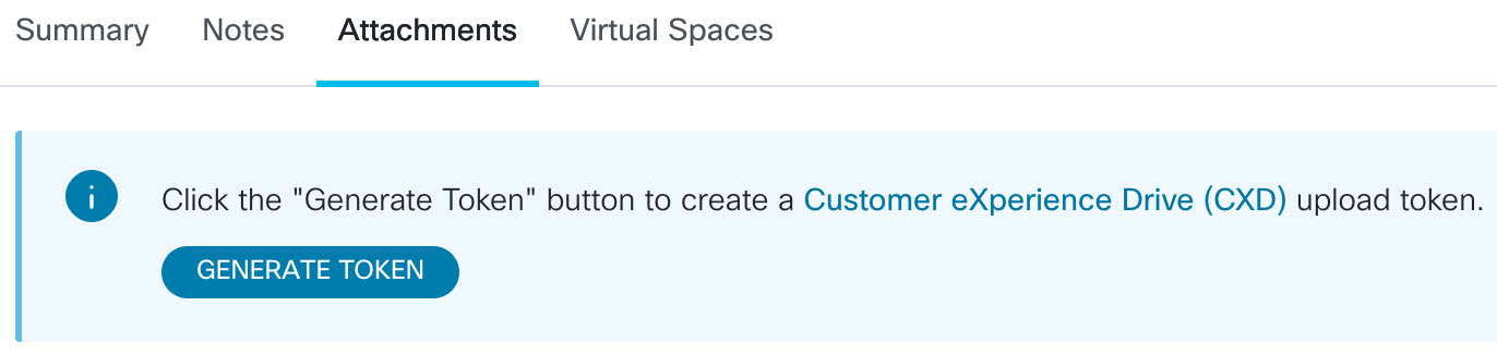
configure terminal
call-home
diagnostic-signature
LocalGateway(cfg-call-home-diag-sign)environment ds_fsurl_prefix "scp://:@cxd.cisco.com"
end
דוגמה:
call-home diagnostic-signature environment ds_fsurl_prefix " environment ds_fsurl_prefix "scp://612345678:abcdefghijklmnop@cxd.cisco.com"-
ודא ש-SNMP מופעל באמצעות הפקודה show snmp. אם SNMP אינו מופעל, הגדר את הפקודה snmp-server manager.
show snmp %SNMP agent not enabled config t snmp-server manager end -
אנו ממליצים להתקין את ניטור ה-High CPU monitoring DS 64224 כאמצעי יזום להשבתת כל ניפויי הבאגים וחתימות האבחון בזמן ניצול CPU גבוה. הורד את DS 64224 באמצעות האפשרויות הבאות ב-Diagnostic Signatures Lookup Tool:
שם שדה
ערך שדה
פלטפורמה
תוכנת Cisco 4300, סדרת 4400 ISR, או Catalyst 8000V Edge
מוצר
CUBE Enterprise בפתרון Webex Calling
היקף בעיה
ביצועים
סוג בעיה
ניצול מעבד גבוה עם התראות דוא"ל.
-
הורד את DS 65095 באמצעות האפשרויות הבאות ב-Diagnostic Signatures Lookup Tool:
שם שדה
ערך שדה
פלטפורמה
תוכנת Cisco 4300, סדרת 4400 ISR, או Catalyst 8000V Edge
מוצר
CUBE Enterprise בפתרון Webex Calling
היקף בעיה
יומני Syslog
סוג בעיה
Syslog - %VOICE_IEC-3-GW: CCAPI: Internal Error (Call spike threshold): IEC=1.1.181.1.29.0
-
העתק את קובצי ה-XML של DS לשער המקומי.
copy ftp://username:password@/DS_64224.xml bootflash: copy ftp://username:password@/DS_65095.xml bootflash: -
התקן את קובץ ניטור ה- DS 64224 בעל צריכת מעבד גבוהה ולאחר מכן את קובץ ה- XML של DS 65095 בשער המקומי.
call-home diagnostic-signature load DS_64224.xml Load file DS_64224.xml success call-home diagnostic-signature load DS_65095.xml Load file DS_65095.xml success -
ודא שהחתימה מותקנת בהצלחה באמצעות show call-home diagnostic-signature. עמודת המצב צריכה לכלול ערך "רשום".
show call-home diagnostic-signature
Current diagnostic-signature settings:
 Diagnostic-signature: enabled
 Profile: CiscoTAC-1 (status: ACTIVE)
 Downloading  URL(s):  https://tools.cisco.com/its/service/oddce/services/DDCEService
 Environment variable:
           ds_email: username@gmail.com
           ds_fsurl_prefix: scp://612345678:abcdefghijklmnop@cxd.cisco.com
חתימות DS שהורדו:
מזהה DS
שם DC
מהדורה
מצב
עדכון אחרון (GMT+00:00)
64224
00:07:45
DS_LGW_CPU_MON75
0.0.10
רשום
2020-11-08:00:07:45
65095
00:12:53
DS_LGW_IEC_Call_spike_threshold
0.0.12
רשום
2020-11-08:00:12:53
אימות ביצוע חתימות אבחון
בפקודה הבאה, עמודת "Status" של הפקודה show call-home diagnostic-signature משתנה ל-"running" בזמן שה-Local Gateway מבצע את הפעולה שהוגדרה בחתימה. הפלט של show call-home diagnostic-signature statistics הוא הדרך הטובה ביותר לוודא האם חתימת אבחון מזהה אירוע מעניין וביצעה את הפעולה. ה “Triggered/Max/Deinstall” העמודה מציינת את מספר הפעמים שהחתימה הנתונה הפעילה אירוע, את מספר הפעמים המרבי שהיא מוגדרת לזהות אירוע, והאם החתימה מסירה את עצמה לאחר זיהוי המספר המרבי של אירועים שהופעלו.
show call-home diagnostic-signature
Current diagnostic-signature settings:
 Diagnostic-signature: enabled
 Profile: CiscoTAC-1 (status: ACTIVE)
 Downloading  URL(s):  https://tools.cisco.com/its/service/oddce/services/DDCEService
 Environment variable:
           ds_email: carunach@cisco.com
           ds_fsurl_prefix: scp://612345678:abcdefghijklmnop@cxd.cisco.com
חתימות DS שהורדו:
|
מזהה DS |
שם DC |
מהדורה |
מצב |
עדכון אחרון (GMT+00:00) |
|---|---|---|---|---|
|
64224 |
DS_LGW_CPU_MON75 |
0.0.10 |
רשום |
2020-11-08 00:07:45 |
|
65095 |
DS_LGW_IEC_Call_spike_threshold |
0.0.12 |
פועל |
2020-11-08 00:12:53 |
הצגת סטטיסטיקות של חתימות אבחון של שיחות טלפון ביתיות
|
מזהה DS |
שם DC |
הופעל/Max/Deinstall |
זמן ריצה ממוצע (שניות) |
זמן ריצה מקסימלי (שניות) |
|---|---|---|---|---|
| 64224 |
DS_LGW_CPU_MON75 |
0/0/N |
0.000 |
0.000 |
|
65095 |
DS_LGW_IEC_Call_spike_threshold |
1/20/Y |
23.053 |
23.053 |
דוא"ל ההתראה שנשלח במהלך ביצוע חתימת אבחון מכיל מידע מפתח כגון סוג הבעיה, פרטי המכשיר, גרסת התוכנה, תצורת ההפעלה ומציג פלטי פקודות הרלוונטיים לפתרון בעיות הבעיה הנתונה.
הסרת ההתקנה של חתימות אבחון
שימוש בחתימות אבחון למטרות פתרון בעיות מוגדר בדרך כלל להסרת התקנה לאחר זיהוי התרחשויות בעיה מסוימות. אם ברצונך להסיר חתימה באופן ידני, אחזר את מזהה ה-DS מהפלט של show call-home diagnostic-signature והרץ את הפקודה הבאה:
call-home diagnostic-signature deinstall דוגמה:
call-home diagnostic-signature deinstall 64224
חתימות חדשות מתווספות לכלי חיפוש חתימות האבחון מעת לעת, בהתבסס על בעיות שנצפות בפריסות. TAC אינו תומך כרגע בבקשות ליצירת חתימות מותאמות אישית חדשות.


