- 主页
- /
- 文章

感谢您的反馈。

将CUBE高可用性作为本地网关
 在此文章中
在此文章中 反馈?
反馈?本地网关(LGW)是为CISCO WEBEX呼叫客户提供本地PSTN访问权限的独家解决方案 。本文档指导您使用CUBE高可用性,使用活动或待机CUBE配置本地网关 ,以确保 活动呼叫的状态故障转移。
基本原则
先决条件
在将Cisco Unified Border Element (CUBE) High Availability (HA)部署为Webex呼叫的本地网关之前,请确保您深入了解以下概念:
-
使用CUBE Enterprise实现状态呼叫保留的2层盒对盒冗余
本文提供的配置指南假设没有现有语音配置的专用本地网关平台。如果正在修改现有CUBE企业部署以同时利用Cisco Webex Calling的本地网关功能,请密切关注已应用的配置,以确保现有呼叫流和功能不会中断,并确保您遵守CUBE HA设计要求。
硬件和软件组件
CUBE HA作为本地网关需要IOS-XE版本17.9.1或更高版本以及支持CUBE HA和LGW功能的平台。
本文中的显示命令和日志基于在vCUBE (CSR 8000v)上实现的Cisco IOS-XE 17.9.1的最小软件版本。
参考材料
以下是针对不同平台的详细的CUBE HA配置指南:
-
Cisco ISR 4K和Cisco Catalyst 8K系列— https://www.cisco.com/c/en/us/td/docs/ios-xml/ios/voice/cube/ios-xe/config/ios-xe-book/m-cube-ha-isr-g3.html
-
CSR 8000v (vCUBE)— https://www.cisco.com/c/en/us/td/docs/ios-xml/ios/voice/cube/ios-xe/config/ios-xe-book/m-cube-ha-csr.html
-
Cisco Webex呼叫的Cisco Preferred Architecture—— https://www.cisco.com/c/dam/en/us/td/docs/solutions/CVD/Collaboration/hybrid/AltDesigns/PA-WbxCall.pdf
Webex呼叫解决方案概述
Cisco Webex Calling是一个协作产品,为客户提供多个PSTN选项的本地化PBX电话服务的多租户云替代方案。
本地网关部署(如下所示)是本文的重点。Webex Calling中的本地网关(基于场所的PSTN)干线允许连接到客户自有的PSTN服务。它还提供与本地IP PBX部署(如Cisco Unified CM)的连接。使用用于SIP的TLS传输和用于媒体的SRTP传输来保护所有进出云的通信。
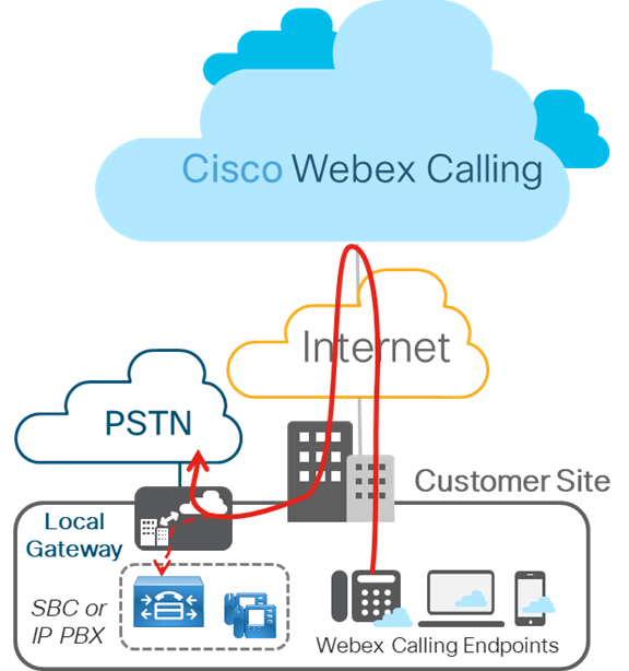
下图显示无任何现有IP PBX的Webex呼叫部署,适用于单个或多站点部署。本文中概述的配置基于此部署。
第2层盒对盒冗余
CUBE HA层2箱对箱冗余使用冗余组(RG)基础设施协议来形成活跃/待机路由器。这对夫妇在各自的界面上共享相同的虚拟IP地址(VIP),并持续交换状态消息。CUBE会话信息通过对路由器进行检查,使备用路由器能够在活动路由器停止服务时立即承担所有CUBE呼叫处理职责,从而导致信号和媒体的状态保存。
检查指向仅限于与媒体包连接的呼叫。传输中的呼叫(例如,尝试或铃声状态)。
在本文中,CUBE HA将指CUBE High Availability (HA) Layer 2 Box-to-Box (B2B)冗余,用于状态呼叫保存。
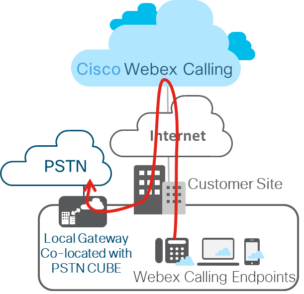
从IOS-XE 17.9.1开始,CUBE HA可以作为Cisco Webex呼叫干线部署(基于场地的PSTN)的本地网关部署。本文将讨论设计考虑因素和配置。该图显示典型的CUBE HA设置为Cisco Webex呼叫干线部署的本地网关。
冗余组下划线组件
冗余组(RG) Infra组件为两个CUBE之间的盒对盒通信基础设施提供支持,并协商最终稳定的冗余状态。此组件还提供:
-
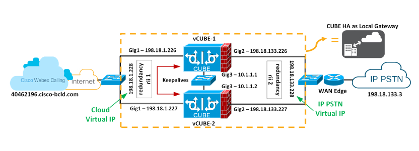
类似HSRP的协议,通过在两个CUBE(通过控制接口)之间交换keepalive和问候消息来协商每个路由器的最终冗余状态——上图中的GigabitEthernet3。
-
用于检查从活动到待机路由器(通过数据接口)的每个呼叫的信号和媒体状态的传输机制——如上图中的GigabitEthernet3。
-
配置和管理流量接口的虚拟IP (VIP)接口(可以使用同一个RG组配置多个流量接口) -千兆以太网1和2被视为流量接口。
此RG组件必须经过专门配置,以支持B2B HA语音。
用于信号和媒体的虚拟IP (VIP)地址管理
B2B HA依赖VIP实现冗余。CUBE HA对中两个CUBE上的VIP和相关的物理接口必须位于同一个LAN子网上。对于语音B2B HA支持,必须配置VIP并将VIP接口绑定到特定语音应用程序(SIP)。外部设备(如Unified CM、Webex呼叫访问SBC、服务提供商或代理)使用VIP作为通过CUBE HA路由器的呼叫的目的地IP地址。因此,从Webex呼叫的角度来看,CUBE HA对作为单个本地网关。
已建立的呼叫信号和RTP会话信息从活动路由器到待机路由器。当活动路由器关闭时,待机路由器接管,并继续转发先前由第一个路由器路由的RTP流。
故障转移时处于瞬态状态的呼叫在切换后不会保留。例如,尚未完全建立或正在通过传输或保留功能进行修改的呼叫。已建立的呼叫可能在切换后断开连接。
使用CUBE HA作为呼叫状态故障转移的本地网关存在以下要求:
-
CUBE HA不能同时放置TDM或模拟接口
-
Gig1和Gig2被称为流量(SIP/RTP)接口,而Gig3是冗余组(RG)控制/数据接口
-
不能将超过2对CUBE HA对放置在同一层2域中,一个带组ID的域1和Group ID2。如果将2个HA对配置为相同的组ID,则RG Control/Data接口需要属于不同的第2层域(vlan、独立开关)
-
RG控制/数据和流量接口都支持端口通道
-
所有信号/媒体都来自/来自虚拟IP地址
-
每当平台在CUBE-HA关系中重新加载时,它总会以待机状态启动
-
所有接口(Gig1、Gig2、Gig3)的较低地址应位于同一平台上
-
冗余界面标识符,rii应是同一层2上的对应/界面组合唯一的
-
两个CUBE上的配置必须相同(包括物理配置),并且必须在相同类型的平台和IOS-XE版本上运行
-
回路接口不能作为绑定使用,因为它们总是挂起
-
多流量(SIP/RTP)接口(Gig1、Gig2)需要配置接口跟踪
-
对于RG-control/数据链接(Gig3)的交叉电缆连接不支持CUBE-HA
-
两个平台必须相同 ,并通过物理开关 连接所有相同接口才能运行,即CUBE-1和CUBE-2的GE0/0/0必须在同一开关,以此类推。
-
不能直接在CUBE上终止WAN或任一侧的DATA HA上终止
-
两个处于活动状态/待机状态都必须位于同一个数据中心
-
必须使用单独的L3接口来处理冗余(RG Control/Data, Gig3)。即用于交通的接口不能用于HA键盘和检查定位。
-
故障转移后,以前活跃的CUBE通过设计、保留信号和介质进行重新加载
在两个CUBE上配置冗余
您必须在HA对中用于生成虚拟IP的两个CUBE上配置两层盒对盒冗余。
| 1 |
配置全局级别的接口跟踪,以跟踪接口的状态。
在RG中使用跟踪CLI来跟踪语音流量接口状态,以便在流量接口关闭后,活动路由将完全发挥其活动作用。 | ||
| 2 |
在应用程序冗余子模式下配置RG与VoIP HA一起使用。
以下是此配置中使用的字段的说明:
| ||
| 3 |
为CUBE应用程序启用盒对盒冗余。配置
冗余-组1—添加和删除此命令需要重新加载,以便更新后的配置生效。应用完所有配置后,我们将重新加载平台。 | ||
| 4 |
将Gig1和Gig2接口与各自的虚拟IP配置,如下所示,并应用冗余接口标识符(rii)
以下是此配置中使用的字段的说明:
| ||
| 5 |
保存第一个立方体的配置并重新加载。 要重新加载的最后一个平台始终是“待机”。
VCUBE-1 完全启动后,请保存 VCUBE-2 的配置并重新加载。
| ||
| 6 |
验证盒对盒配置是否按预期工作。相关输出以粗体高亮显示。 我们上次重新加载了 VCUBE-2 ,根据设计考虑因素;上次重新加载的平台始终是待机。 接下来,在两个HA CUBE上继续执行本地网关配置(基于注册或基于证书)。请参阅在Cisco IOS XE上为Webex呼叫配置本地网关。 |


