- 首頁
- /
- 文章

感謝您的意見回饋。

將 CUBE 高可用性實作為本機閘道
 在此文章中
在此文章中 意見回饋?
意見回饋?本機閘道 (LGW) 是提供內部部署 PSTN 存取的專用解決方案 Cisco Webex Calling 客戶。本文件將指導您設定本機閘道 將 CUBE 高可用性與作用中或備用 CUBE 一起使用,以確保 通話。
基礎
先決條件
在將 Cisco Unified Border Element (CUBE) 高可用性 (HA) 部署為 Webex Calling 的本機閘道之前,請確保您深入了解以下概念:
-
具有 CUBE Enterprise 的第 2 層裝置到裝置備援,可實現有狀態的通話保留
本文章中提供的設定指南假設為專用本機閘道平台,且沒有現有的語音設定。如果修改現有的 CUBE 企業部署以同時利用 Cisco Webex Calling 的本機閘道功能,請密切注意所套用的設定,以確保現有通話流程和功能不會中斷,並確保您遵循 CUBE HA 設計要求。
硬體和軟體元件
CUBE HA 作為本機閘道需要 IOS-XE 版本 17.9.1 或更高版本,以及同時支援 CUBE HA 和 LGW 功能的平台。
本文中的顯示指令和日誌基於在 vCUBE (CSR 8000v) 上實作的 Cisco IOS-XE 17.9.1 的最低軟體版本。
參考資料
以下是各種平台的一些詳細 CUBE HA 設定指南:
-
Cisco ISR 4K 和 Cisco Catalyst 8K 系列 — https://www.cisco.com/c/en/us/td/docs/ios-xml/ios/voice/cube/ios-xe/config/ios-xe-book/m-cube-ha-isr-g3.html
-
CSR 8000v (vCUBE)— https://www.cisco.com/c/en/us/td/docs/ios-xml/ios/voice/cube/ios-xe/config/ios-xe-book/m-cube-ha-csr.html
-
Cisco Webex Calling 的 Cisco 偏好架構 — https://www.cisco.com/c/dam/en/us/td/docs/solutions/CVD/Collaboration/hybrid/AltDesigns/PA-WbxCall.pdf
Webex Calling 解決方案概觀
Cisco Webex Calling 是一種協作產品,它為內部部署 PBX 電話服務提供基於多租戶雲端的替代方案,並為客戶提供多個 PSTN 選項。
本機閘道部署(如下所示)是本文的重點。Webex Calling 中的本機閘道(內部部署型 PSTN)幹線允許連線至客戶擁有的 PSTN 服務。它還提供與內部部署 IP PBX 部署(例如 Cisco Unified CM)的連線。使用適用於 SIP 的 TLS 傳輸和適用於媒體的 SRTP 來保護進出雲端的所有通訊。
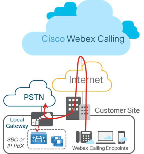
下圖顯示沒有任何現有 IP PBX 的 Webex Calling 部署,適用於單站點或多站點部署。本文中概述的設定基於此部署。
第 2 層 Box 到 Box 備援
CUBE HA 第 2 層機器到機器備援使用備援群組 (RG) 基礎架構通訊協定來形成一對作用中/備用路由器。此配對在其各自的介面上共用相同的虛擬 IP 位址 (VIP),並持續交換狀態訊息。CUBE 作業階段資訊會在路由器配對中進行檢查點,使備用路由器能夠在作用中路由器停止服務時立即接管所有 CUBE 通話處理職責,從而以有狀態保留訊號和媒體。
檢查點僅限於包含媒體封包的連線通話。傳輸中的通話不會被檢查(例如,嘗試或響鈴狀態)。
在本文中,CUBE HA 將參考 CUBE 高可用性 (HA) 第 2 層裝置到裝置 (B2B) 備援,以進行有狀態的通話保留。
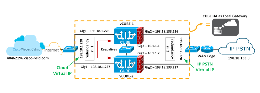
從 IOS-XE 17.9.1 開始,CUBE HA 可以部署為 Cisco Webex Calling 幹線部署(基於內部部署的 PSTN)的本機閘道。本文將討論設計注意事項和設定。該圖顯示了典型的 CUBE HA 設定,作為 Cisco Webex Calling 中繼線部署的本機閘道。
備援群組基礎結構元件
備援群組 (RG) 基礎結構元件提供兩個 CUBE 之間的裝置到裝置通訊基礎結構支援,並協商最終穩定的備援狀態。此元件還提供:
-
類似 HSRP 的通訊協定,透過在兩個 CUBE(透過控制介面)(上圖中的 GigabitEthernet3)之間交換 keepalive 和 hello 訊息來協商每個路由器的最終備援狀態。
-
一種傳輸機制,用於為從作用中路由器到備用路由器(透過資料介面)的每個通話檢查點訊號和媒體狀態 — 上圖中的 GigabitEthernet3。
-
設定和管理流量介面的虛擬 IP (VIP) 介面(可以使用相同的 RG 群組設定多個流量介面)– GigabitEthernet 1 和 2 被視為流量介面。
必須專門設定此 RG 元件以支援語音 B2B HA。
訊號和媒體的虛擬 IP (VIP) 位址管理
B2B HA 依賴 VIP 來實現備援。CUBE HA 配對中兩個 CUBE 上的 VIP 和關聯的實體介面必須位於相同的 LAN 子網路。語音 B2B HA 支援必須設定 VIP 並將 VIP 介面綁定至特定語音應用程式 (SIP)。外部裝置(例如 Unified CM、Webex Calling 存取 SBC、服務提供者或 Proxy)使用 VIP 作為穿越 CUBE HA 路由器的通話的目的地 IP 位址。因此,從 Webex Calling 的角度來看,CUBE HA 配對充當單一本機閘道。
已建立通話的通話訊號和 RTP 作業階段資訊會從作用中路由器到備用路由器進行檢查點。當 Active 路由器關閉時,Standby 路由器會接管,並繼續轉送先前由第一個路由器路由的 RTP 串流。
在容錯移轉時處於暫時狀態的通話將不會在切換後保留。例如,尚未完全建立的通話或正在使用轉接或保留功能修改的通話。已建立的通話可能會在切換後中斷連線。
使用 CUBE HA 作為有狀態的通話故障轉移的本機閘道時,存在下列需求:
-
CUBE HA 不能將 TDM 或類比介面置於同一位置
-
Gig1 和 Gig2 稱為流量 (SIP/RTP) 介面,而 Gig3 是備援群組 (RG) 控制/資料介面
-
在同一個第 2 層網域中最多只能放置 2 個 CUBE HA 配對,其中一個配對具有群組 ID 1 和其他群組 ID 為 2 的群組。如果使用相同的群組 id 設定 2 個 HA 配對,則 RG 控制/資料介面需要屬於不同的第 2 層網域(vlan、單獨的交換器)
-
RG 控制/資料和流量介面都支援連接埠通道
-
所有訊號/媒體的來源/來源為虛擬 IP 位址
-
每當在 CUBE-HA 關係中重新載入平台時,它總是以待命狀態啟動
-
所有介面(Gig1、Gig2、Gig3)的較低位址應該位於相同的平台上
-
備援介面識別元, rii 對於相同第 2 層上的配對/介面組合應該是唯一的
-
兩個 CUBE 上的設定(包括實體設定)必須相同,並且必須在相同類型的平台和 IOS-XE 版本上執行
-
迴圈介面無法用作綁定,因為它們始終處於啟動狀態
-
多個流量 (SIP/RTP) 介面(Gig1、Gig2)需要設定介面追踪
-
RG 控制/資料鏈結 (Gig3) 的交叉纜線連線不支援 CUBE-HA
-
兩個平台都必須相同 並透過實體交換器 跨所有類似的介面,CUBE HA 才能運作,即 CUBE-1 和 CUBE-2 的 GE0/0/0 必須在相同的交換器上終止,依此類推。
-
不能直接在 CUBE 上終止 WAN 或在任一側終止資料 HA
-
Active/Standby 必須位於相同的資料中心
-
必須使用單獨的 L3 介面進行備援(RG 控制/資料,Gig3)。即,用於流量的介面不能用於 HA keepalive 和檢查點
-
容錯移轉時,先前作用中的 CUBE 會根據設計進行重新載入,保留訊號和媒體
在兩個 CUBE 上設定備援
您必須在兩個要在 HA 配對中使用的 CUBE 上設定第 2 層機器到機器備援,以啟動虛擬 IP。
| 1 |
在全域層級配置介面追踪以追踪介面的狀態。
在 RG 中使用追踪 CLI 來追踪語音流量介面狀態,以便在流量介面關閉後,作用中路由將完全發揮作用。 | ||
| 2 |
配置 RG 以在應用程式備援子模式下與 VoIP HA 一起使用。
以下是此組態中使用的欄位的說明:
| ||
| 3 |
為 CUBE 應用程式啟用裝置到裝置備援。在上一步中設定 RG
備援群組 1 — 新增和移除此指令需要重新載入,更新的組態才能生效。我們將在套用所有設定後重新載入平台。 | ||
| 4 |
使用各自的虛擬 IP 設定 Gig1 和 Gig2 介面,如下所示,並套用備援介面識別碼 ( rii )
以下是此組態中使用的欄位的說明:
| ||
| 5 |
儲存第一個 CUBE 的組態並重新載入。 最後重新載入的平台永遠是待命平台。
之後VCUBE-1完全啟動,請儲存VCUBE-2 並重新載入。
| ||
| 6 |
驗證裝置到裝置組態是否如預期運作。相關輸出在粗體。 我們已重新載入VCUBE-2 最後,並根據設計考量;最後重新載入的平台將永遠是待命。 接下來,在兩個 HA CUBE 上繼續進行本機閘道設定(基於註冊或基於憑證)。請參閱在 Cisco IOS XE 上為 Webex Calling 設定本機閘道。 |


