
Thanks for your feedback.
 Feedback?
Overview
Webex Calling currently supports two versions of Local Gateway:
-
Local Gateway
-
Local Gateway for Webex for Government
-
Before you begin, understand the premises-based Public Switched Telephone Network (PSTN) and Local Gateway (LGW) requirements for Webex Calling. See Cisco Preferred Architecture for Webex Calling for more information.
-
This article assumes that a dedicated Local Gateway platform is in place with no existing voice configuration. If you modify an existing PSTN gateway or CUBE Enterprise deployment to use as the Local Gateway function for Webex Calling, then pay careful attention to the configuration. Ensure that you don't interrupt the existing call flows and functionality because of the changes that you make.
The procedures contain links to command reference documentation where you can learn more about the individual command options. All command reference links go to the Webex Managed Gateways Command Reference unless stated otherwise (in which case, the command links go to Cisco IOS Voice Command Reference). You can access all these guides at Cisco Unified Border Element Command References.
For information on the supported third-party SBCs, refer to the respective product reference documentation.
There are two options to configure the Local Gateway for your Webex Calling trunk:
-
Registration-based trunk
-
Certificate-based trunk
Use the task flow either under the Registration-based Local Gateway or Certificate-based Local Gateway to configure Local Gateway for your Webex Calling trunk.
See Get started with Local Gateway for more information on different trunk types. Perform the following steps on the Local Gateway itself, using the Command Line Interface (CLI). We use Session Initiation Protocol (SIP) and Transport Layer Security (TLS) transport to secure the trunk and Secure Real Time Protocol (SRTP) to secure the media between the Local Gateway and Webex Calling.
-
Select CUBE as your Local Gateway. Webex for Government doesn’t currently support any third-party Session Border Controllers (SBCs). To review the latest list, see Get started with Local Gateway.
- Install Cisco IOS XE Dublin 17.12.1a or later versions for all Webex for Government Local Gateways.
-
To review the list of root Certificate Authorities (CAs) that Webex for Government support, see Root certificate authorities for Webex for Government.
-
For details on the external port ranges for Local Gateway in Webex for Government, see Network requirements for Webex for Government (FedRAMP).
Local Gateway for Webex for Government doesn’t support the following:
-
STUN/ICE-Lite for media path optimization
-
Fax (T.38)
To configure Local Gateway for your Webex Calling trunk in Webex for Government, use the following option:
-
Certificate-based trunk
Use the task flow under the Certificate-based Local Gateway to configure the Local Gateway for your Webex Calling trunk. For more details on how to configure a certificate-based Local Gateway, see Configure Webex Calling certificate-based trunk.
It’s mandatory to configure FIPS-compliant GCM ciphers to support Local Gateway for Webex for Government. If not, the call setup fails. For configuration details, see Configure Webex Calling certificate-based trunk.
Webex for Government doesn’t support registration-based Local Gateway.
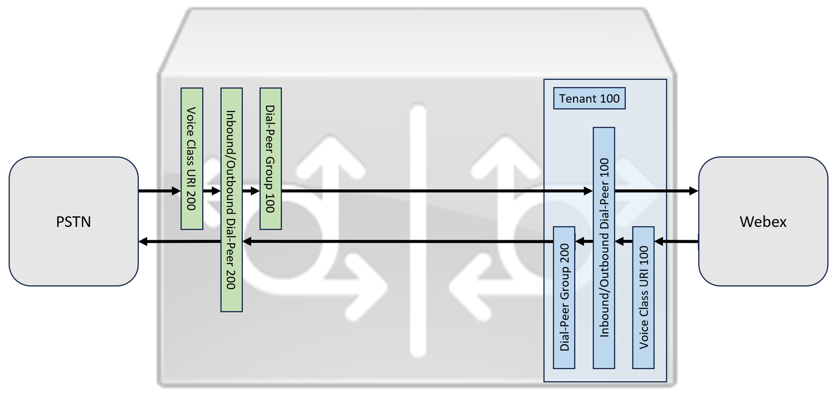
This section describes how to configure a Cisco Unified Border Element (CUBE) as a Local Gateway for Webex Calling, using a registering SIP trunk. The first part of this document illustrates how to configure a simple PSTN gateway. In this case, all calls from the PSTN are routed to Webex Calling and all calls from Webex Calling are routed to the PSTN. The image below highlights this solution and the high-level call routing configuration that will be followed.
In this design, the following principal configurations are used:
-
voice class tenants: Used to create trunk specific configurations.
-
voice class uri: Used to classify SIP messages for the selection of an inbound dial-peer.
-
inbound dial-peer: Provides treatment for inbound SIP messages and determines the outbound route using a dial-peer group.
-
dial-peer group: Defines the outbound dial-peers used for onward call routing.
-
outbound dial-peer: Provides treatment for outbound SIP messages and routes them to the required target.
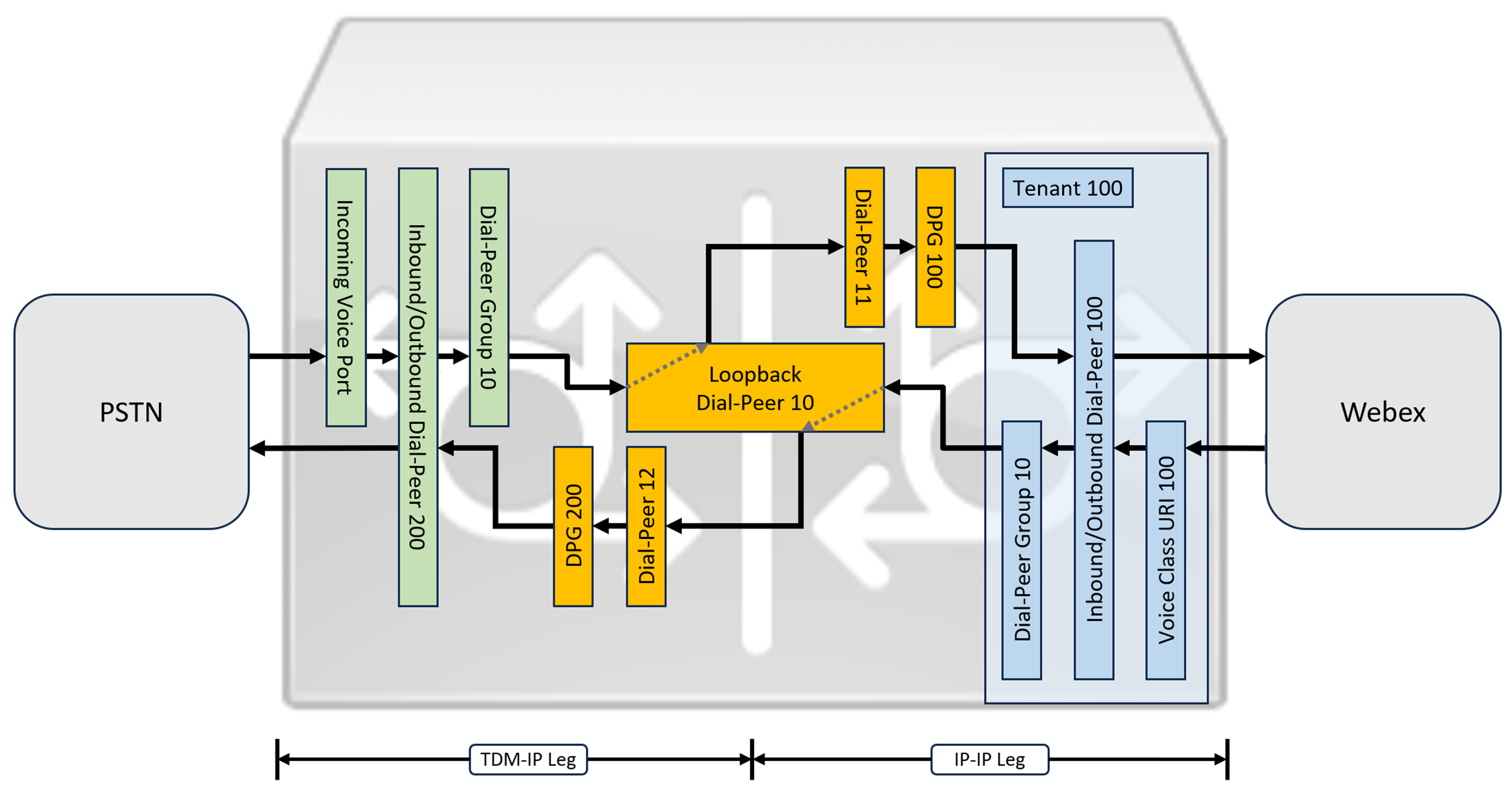
While IP and SIP have become the default protocols for PSTN trunks, TDM (Time Division Multiplexing) ISDN circuits are still widely used and are supported with Webex Calling trunks. To enable media optimization of IP paths for Local Gateways with TDM-IP call flows, it is currently necessary to use a two-leg call routing process. This approach modifies the call routing configuration shown above, by introducing a set of internal loop-back dial-peers between Webex Calling and PSTN trunks as illustrated in the image below.
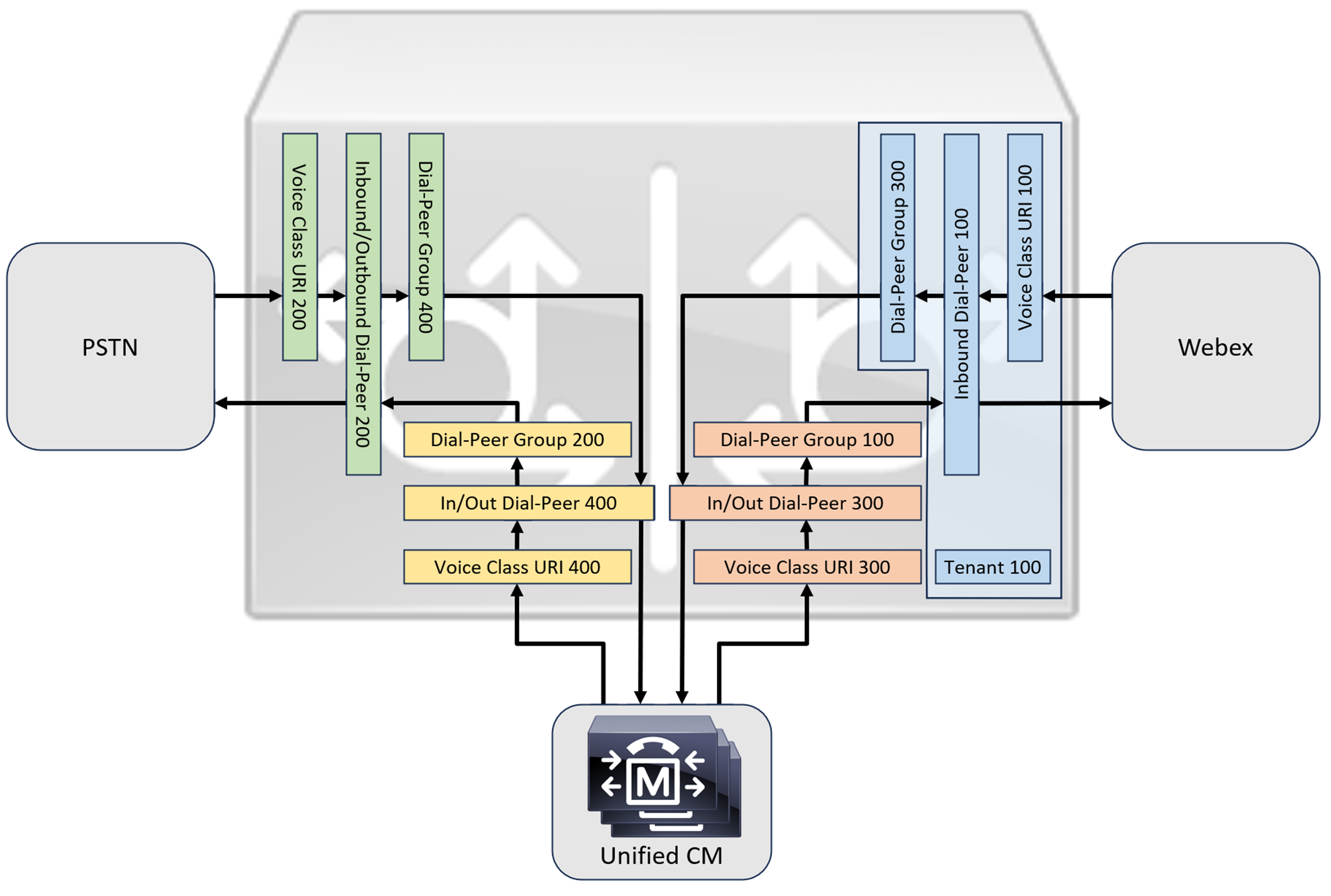
When connecting an on-premises Cisco Unified Communications Manager solution with Webex Calling, you can use the simple PSTN gateway configuration as a baseline for building the solution illustrated in the following diagram. In this case, Unified Communications Manager provides centralized routing and treatment of all PSTN and Webex Calling calls.
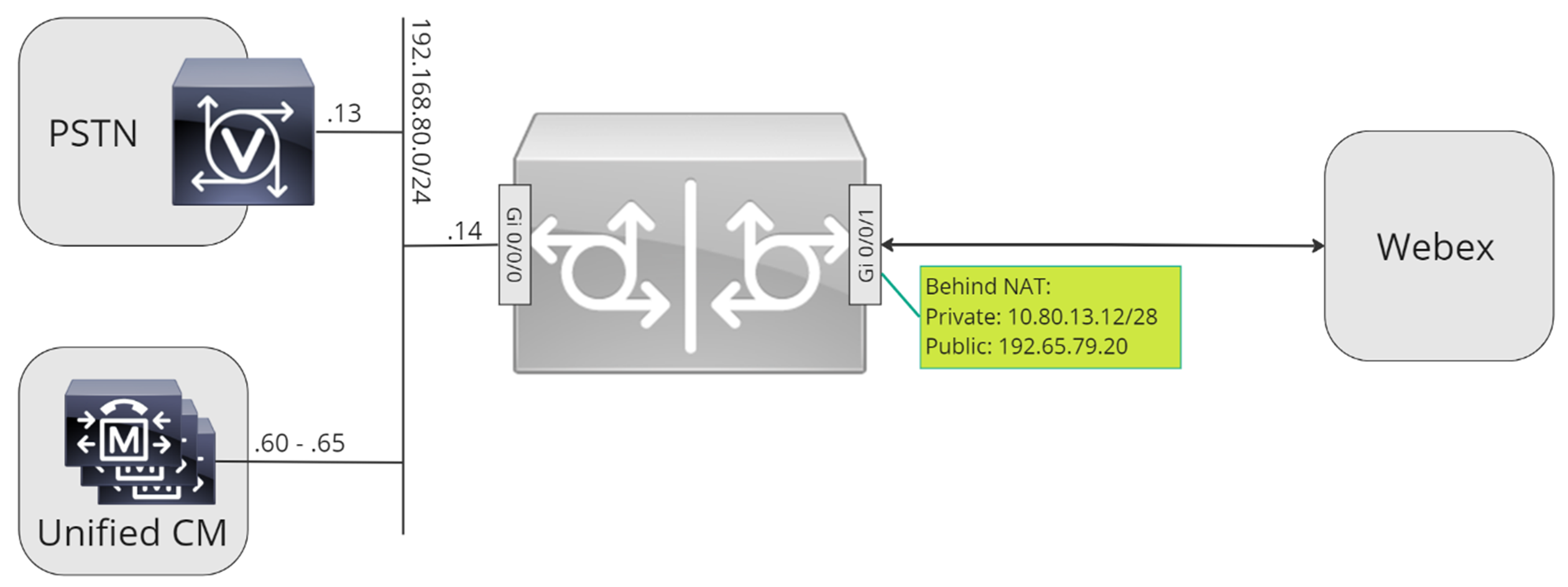
Throughout this document, the host names, IP addresses, and interfaces illustrated in the following image are used.
Use the configuration guidance in the rest of this document to complete your Local Gateway configuration as follows:
-
Step 1: Configure router baseline connectivity and security
-
Step 2: Configure Webex Calling Trunk
Depending on your required architecture, follow either:
-
Step 3: Configure Local Gateway with SIP PSTN trunk
-
Step 4: Configure Local Gateway with an existing Unified CM environment
Or:
-
Step 3: Configure Local Gateway with TDM PSTN trunk
Baseline configuration
The first step in preparing your Cisco router as a Local Gateway for Webex Calling is to build a baseline configuration that secures your platform and establishes connectivity.
-
All registration-based Local Gateway deployments require Cisco IOS XE 17.6.1a or later versions. Cisco IOS 17.12.2 or later is recommended. For the recommended versions, see the Cisco Software Research page. Search for the platform and select one of the suggested releases.
-
ISR4000 series routers must be configured with both Unified Communications and Security technology licenses.
-
Catalyst Edge 8000 series routers fitted with voice cards or DSPs require DNA Advantage licensing. Routers without voice cards or DSPs require a minimum of DNA Essentials licensing.
-
-
Build a baseline configuration for your platform that follows your business policies. In particular, configure and verify the following:
-
NTP
-
ACLs
-
User authentication and remote access
-
DNS
-
IP routing
-
IP addresses
-
-
The network toward Webex Calling must use an IPv4 address.
-
Upload the Cisco root CA bundle to the Local Gateway.
When configuring the tenant-side to connect with Webex Calling, only SRV-based addresses are supported.
Configuration
| 1 |
Ensure that you assign valid and routable IP addresses to any Layer 3 interfaces, for example:
|
| 2 |
Protect registration and STUN credentials on the router using symmetric encryption. Configure the primary encryption key and encryption type as follows:
|
| 3 |
Create a placeholder PKI trustpoint. Requires this trustpoint to configure TLS later. For registration-based trunks, this trustpoint doesn't require a certificate - as required for a certificate-based trunk. |
| 4 |
Enable TLS1.2 exclusivity and specify the default trustpoint using the following configuration commands. Update the Transport parameters to ensure a reliable secure connection for registration: The
|
| 5 |
Install the Cisco root CA bundle, which includes the IdenTrust Commercial Root CA1 certificate used by Webex Calling. Use the crypto pki trustpool import clean url command to download the root CA bundle from the specified URL, and to clear the current CA trustpool, then install the new bundle of certificates: If you need to use a proxy for access to the internet using HTTPS, add the following configuration before importing the CA bundle: ip http client proxy-server yourproxy.com proxy-port 80 |
| 1 |
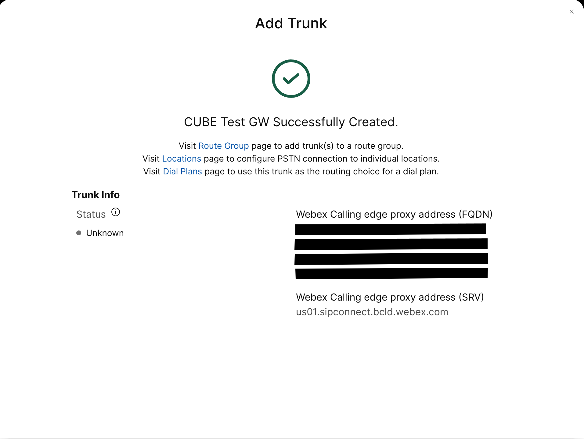
Create a registration based PSTN trunk for an existing location in the Control Hub. Make a note of the trunk information that is provided once the trunk has been created. The details highlighted in the illustration are used in the configuration steps in this guide. For more information, see Configure trunks, route groups, and dial plans for Webex Calling. 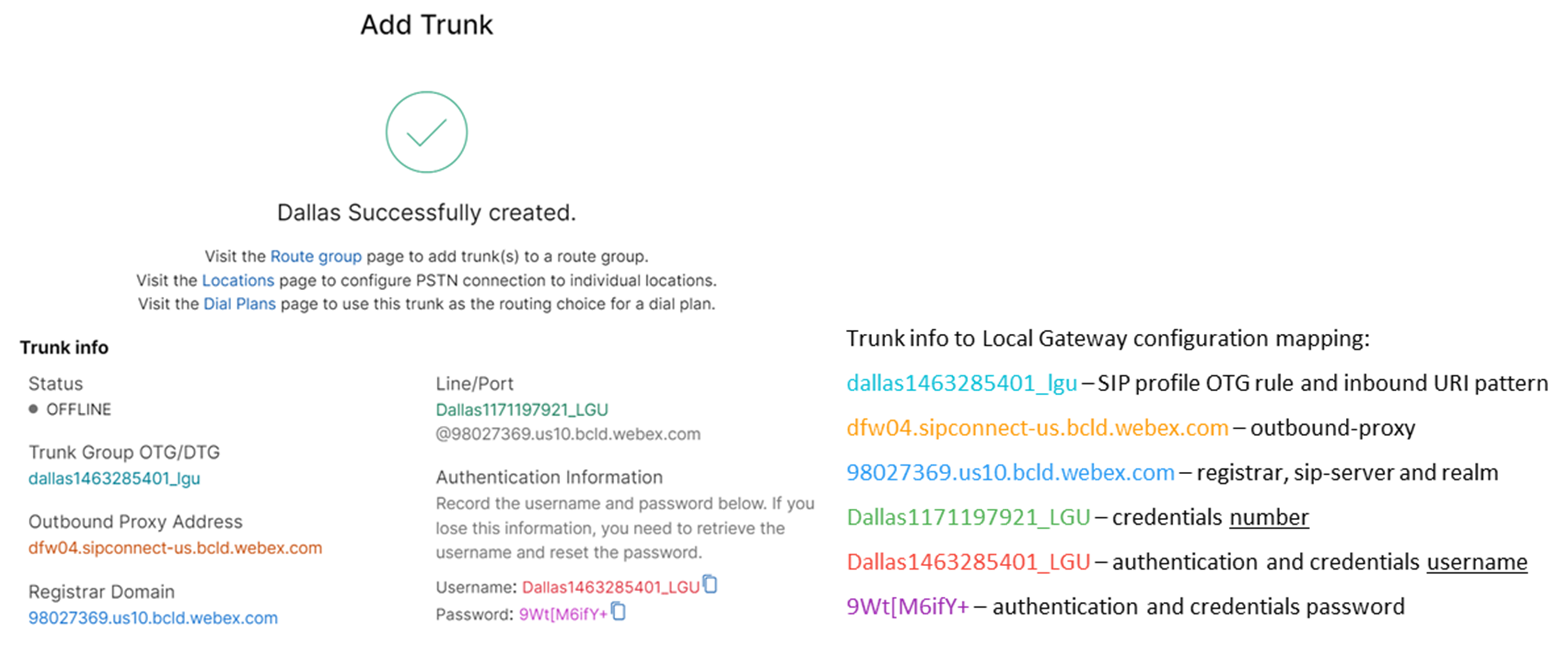
|
| 2 |
Enter the following commands to configure CUBE as a Webex Calling Local Gateway: Here's an explanation of the fields for the configuration:
Enables Cisco Unified Border Element (CUBE) features on the platform. media statisticsEnables media monitoring on the Local Gateway. media bulk-statsEnables the control plane to poll the data plane for bulk call statistics. For more information on these commands, see Media. allow-connections sip to sipEnable CUBE basic SIP back-to-back user agent functionality. For more information, see Allow connections. By default, T.38 fax transport is enabled. For more information, see fax protocol t38 (voice-service). Enables STUN (Session Traversal of UDP through NAT) globally.
For more information, see stun flowdata agent-id and stun flowdata shared-secret. asymmetric payload fullConfigures SIP asymmetric payload support for both DTMF and dynamic codec payloads. For more information, see asymmetric payload. early-offer forcedForces the Local Gateway to send SDP information in the initial INVITE message instead of waiting for acknowledgment from the neighboring peer. For more information on this command, see early-offer. |
| 3 |
Configure voice class codec 100 allowing G.711 codecs only for all trunks. This simple approach is suitable for most deployments. If required, additional codec types supported by both originating and terminating systems may be added to the list. More complex solutions involving transcoding using DSP modules are supported, but not included in this guide. Here's an explanation of the fields for the configuration: voice class codec 100Used to only allow preferred codecs for SIP trunk calls. For more information, see voice class codec. |
| 4 |
Configure voice class stun-usage 100 to enable ICE on the Webex Calling trunk. Here's an explanation of the fields for the configuration: stun usage ice liteUsed to enable ICE-Lite for all Webex Calling facing dial-peers to allow media-optimization whenever possible. For more information, see voice class stun usage and stun usage ice lite. Media optimization is negotiated wherever possible. If a call requires cloud media services, such as recording, the media cannot be optimized. |
| 5 |
Configure the media encryption policy for Webex traffic. Here's an explanation of the fields for the configuration: voice class srtp-crypto 100Specifies SHA1_80 as the only SRTP cipher-suite CUBE offers in the SDP in offer and answer messages. Webex Calling only supports SHA1_80. For more information, see voice class srtp-crypto. |
| 6 |
Configure a pattern to identify calls to a Local Gateway trunk based on its destination trunk parameter: Here's an explanation of the fields for the configuration: voice class uri 100 sipDefines a pattern to match an incoming SIP invite to an incoming trunk dial-peer. When entering this pattern, use dtg= followed by the Trunk OTG/DTG value provided in the Control Hub when the trunk was created. For more information, see voice class uri. |
| 7 |
Configure sip profile 100, which will be used to modify SIP messages before they are sent to Webex Calling.
Here's an explanation of the fields for the configuration:
United States or Canadian PSTN provider can offer the Caller ID verification for Spam and fraud calls, with the additional configuration mentioned in the Spam or fraud call indication in Webex Calling article. |
| 8 |
Configure Webex Calling trunk: |
| 9 |
To configure network devices such as CUBE and to forward Session Initiation Protocol (SIP) headers that the device doesn't process, use these commands. These commands enable the device to pass through unsupported SIP headers, including geo-location headers and PIDF-LO (Presence Information Data Format - Location Object), on the local gateway. This functionality supports Nomadic E911 services by ensuring that critical location information is preserved and forwarded correctly. |
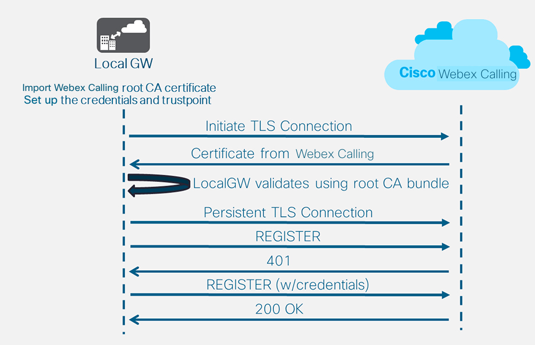
After you define the tenant 100 and configure a SIP VoIP dial-peer, the gateway initiates a TLS connection toward Webex Calling. At this point, the access SBC presents its certificate to the Local Gateway. The Local Gateway validates the Webex Calling access SBC certificate using the CA root bundle that was updated earlier. If the certificate is recognized, a persistent TLS session is established between the Local Gateway and Webex Calling access SBC. The Local Gateway is then able to use this secure connection to register with the Webex access SBC. When the registration is challenged for authentication:
-
The username, password, and realm parameters from the credentials configuration is used in the response.
-
The modification rules in sip profile 100 are used to convert SIPS URL back to SIP.
Registration is successful when a 200 OK is received from the access SBC.
Having built a trunk towards Webex Calling above, use the following configuration to create a non-encrypted trunk towards a SIP based PSTN provider:
If your Service Provider offers a secure PSTN trunk, you may follow a similar configuration as detailed above for the Webex Calling trunk. CUBE supports secure call routing.
If you are using a TDM / ISDN PSTN trunk, skip to the next section Configure Local Gateway with TDM PSTN trunk.
To configure TDM interfaces for PSTN call legs on the Cisco TDM-SIP Gateways, see Configuring ISDN PRI.
| 1 |
Configure the following voice class uri to identify inbound calls from the PSTN trunk: Here's an explanation of the fields for the configuration: voice class uri 200 sipDefines a pattern to match an incoming SIP invite to an incoming trunk dial-peer. When entering this pattern, use the IP address of your IP PSTN gateway. For more information, see voice class uri. |
| 2 |
Configure the following IP PSTN dial-peer: Here's an explanation of the fields for the configuration: Defines a VoIP dial-peer with a tag of 200 and gives a meaningful description for ease of management and troubleshooting. For more information, see dial-peer voice. destination-pattern BAD.BADA dummy destination pattern is required when routing outbound calls using an inbound dial-peer group. Any valid destination pattern may be used in this case. For more information, see destination-pattern (interface). session protocol sipv2Specifies that this dial-peer handles SIP call legs. For more information, see session protocol (dial peer). session target ipv4: 192.168.80.13Specifies the target address for calls sent to the PSTN provider. This could be either an IP address or DNS host name. For more information, see session target (VoIP dial peer). incoming uri via 200Specifies the voice class used to match incoming calls to this dial-peer using the INVITE VIA header URI. For more information, see incoming url.
voice-class sip asserted-id pai
(Optional) Turns on P-Asserted-Identity header processing and controls how this is used for the PSTN trunk. If this command is used, the calling party identity provided from the incoming dial-peer is used for the outgoing From and P-Asserted-Identity headers. If this command is not used, the calling party identity provided from the incoming dial-peer is used for the outgoing From and Remote-Party-ID headers. For more information, see voice-class sip asserted-id.
bind control
source-interface
GigabitEthernet0/0/0
Configures the source interface and associated IP address for messages sent to the PSTN. For more information, see bind. bind media source-interface GigabitEthernet0/0/0Configures the source interface and associated IP address for media sent to PSTN. For more information, see bind. voice-class codec 100Configures the dial-peer to use the common codec filter list 100. For more information, see voice-class codec. dtmf-relay rtp-nteDefines RTP-NTE (RFC2833) as the DTMF capability expected on the call leg. For more information, see DTMF Relay (Voice over IP). no vadDisables voice activity detection. For more information, see vad (dial peer). |
| 3 |
If you are configuring your Local Gateway to only route calls between Webex Calling and the PSTN, add the following call routing configuration. If you are configuring your Local Gateway with a Unified Communications Manager platform, skip to the next section. |
Having built a trunk towards Webex Calling, use the following configuration to create a TDM trunk for your PSTN service with loop-back call routing to allow media optimization on the Webex call leg.
If you do not require IP media optimization, follow the configuration steps for a SIP PSTN trunk. Use a voice port and POTS dial-peer (as shown in Steps 2 and 3) instead of the PSTN VoIP dial-peer.
| 1 |
The loop-back dial-peer configuration uses dial-peer groups and call routing tags to ensure that calls pass correctly between Webex and the PSTN, without creating call routing loops. Configure the following translation rules that will be used to add and remove the call routing tags: Here's an explanation of the fields for the configuration: voice translation-ruleUses regular expressions defined in rules to add or remove call routing tags. Over-decadic digits (‘A’) are used to add clarity for troubleshooting. In this configuration, the tag added by translation-profile 100 is used to guide calls from Webex Calling towards the PSTN via the loopback dial-peers. Similarly, the tag added by translation-profile 200 is used to guide calls from the PSTN towards Webex Calling. Translation-profiles 11 and 12 remove these tags before delivering calls to the Webex and PSTN trunks respectively. This example assumes that called numbers from Webex Calling are presented in +E.164 format. Rule 100 removes the leading + to maintain a valid called number. Rule 12 then adds a national or international routing digit(s) when removing the tag. Use digits that suit your local ISDN national dial plan. If Webex Calling presents numbers in national format, adjust rules 100 and 12 to simply add and remove the routing tag respectively. For more information, see voice translation-profile and voice translation-rule. |
| 2 |
Configure TDM voice interface ports as required by the trunk type and protocol used. For more information, see Configuring ISDN PRI. For example, the basic configuration of a Primary Rate ISDN interface installed in NIM slot 2 of a device might include the following: |
| 3 |
Configure the following TDM PSTN dial-peer: Here's an explanation of the fields for the configuration: Defines a VoIP dial-peer with a tag of 200 and gives a meaningful description for ease of management and troubleshooting. For more information, see dial-peer voice. destination-pattern BAD.BADA dummy destination pattern is required when routing outbound calls using an inbound dial-peer group. Any valid destination pattern may be used in this case. For more information, see destination-pattern (interface). translation-profile incoming 200Assigns the translation profile that will add a call routing tag to the incoming called number. direct-inward-dialRoutes the call without providing a secondary dial-tone. For more information, see direct-inward-dial. port 0/2/0:15The physical voice port associated with this dial-peer. |
| 4 |
To enable media optimization of IP paths for Local Gateways with TDM-IP call flows, you can modify the call routing by introducing a set of internal loop-back dial-peers between Webex Calling and PSTN trunks. Configure the following loop-back dial-peers. In this case, all incoming calls will be routed initially to dial-peer 10 and from there to either dial-peer 11 or 12 based on the applied routing tag. After removal of the routing tag, calls will be routed to the outbound trunk using dial-peer groups. Here's an explanation of the fields for the configuration: Defines a VoIP dial-peer and gives a meaningful description for ease of management and troubleshooting. For more information, see dial-peer voice. translation-profile incoming 11Applies the translation profile defined earlier to remove the call routing tag before passing to the outbound trunk. destination-pattern BAD.BADA dummy destination pattern is required when routing outbound calls using an inbound dial-peer group. For more information, see destination-pattern (interface). session protocol sipv2Specifies that this dial-peer handles SIP call legs. For more information, see session protocol (dial peer). session target ipv4: 192.168.80.14Specifies the local router interface address as the call target to loop-back. For more information, see session target (voip dial peer). bind control source-interface GigabitEthernet0/0/0Configures the source interface and associated IP address for messages sent through the loop-back. For more information, see bind. bind media source-interface GigabitEthernet0/0/0Configures the source interface and associated IP address for media sent through the loop-back. For more information, see bind. dtmf-relay rtp-nteDefines RTP-NTE (RFC2833) as the DTMF capability expected on the call leg. For more information, see DTMF Relay (Voice over IP). codec g711alaw Forces all PSTN calls to use G.711. Select a-law or u-law to match the companding method used by your ISDN service. no vadDisables voice activity detection. For more information, see vad (dial peer). |
| 5 |
Add the following call routing configuration: This concludes your Local Gateway configuration. Save the configuration and reload the
platform if this is the first time CUBE features are configured.
|
The PSTN-Webex Calling configuration in the previous sections may be modified to include additional trunks to a Cisco Unified Communications Manager (UCM) cluster. In this case, all calls are routed via Unified CM. Calls from UCM on port 5060 are routed to the PSTN and calls from port 5065 are routed to Webex Calling. The following incremental configurations may be added to include this calling scenario.
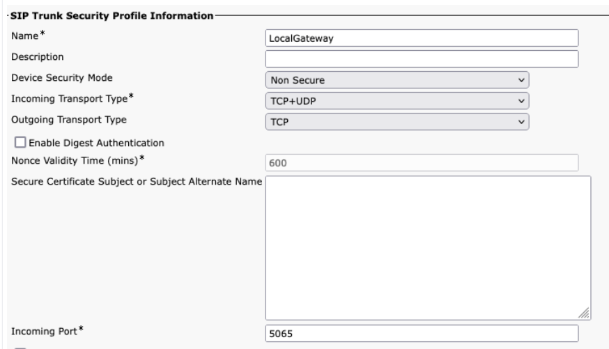
When creating the Webex Calling trunk in Unified CM, ensure that you configure the incoming port in the SIP Trunk Security Profile settings to 5065. This allows incoming messages on port 5065 and populate the VIA header with this value when sending messages to the Local Gateway.
| 1 |
Configure the following voice class URIs: |
| 2 |
Configure the following DNS records to specify SRV routing to Unified CM hosts: IOS XE uses these records for locally determining target UCM hosts and ports. With this configuration, it is not required to configure records in your DNS system. If you prefer to use your DNS, then these local configurations are not required. Here's an explanation of the fields for the configuration: The following command creates a DNS SRV resource record. Create a record for each UCM host and trunk: ip host _sip._udp.pstntocucm.io srv 2 1 5060 ucmsub5.mydomain.com _sip._udp.pstntocucm.io: SRV resource record name 2: The SRV resource record priority 1: The SRV resource record weight 5060: The port number to use for the target host in this resource record ucmsub5.mydomain.com: The resource record target host To resolve the resource record target host names, create local DNS A records. For example: ip host ucmsub5.mydomain.com 192.168.80.65 ip host: Creates a record in the local IOS XE database. ucmsub5.mydomain.com: The A record host name. 192.168.80.65: The host IP address. Create the SRV resource records and A records to reflect your UCM environment and preferred call distribution strategy. |
| 3 |
Configure the following dial-peers: |
| 4 |
Add call routing using the following configurations: |
Diagnostic Signatures (DS) proactively detects commonly observed issues in the IOS XE-based Local Gateway and generates email, syslog, or terminal message notification of the event. You can also install the DS to automate diagnostics data collection and transfer-collected data to the Cisco TAC case to accelerate resolution time.
Diagnostic Signatures (DS) are XML files that contain information about problem trigger events and actions to be taken to inform, troubleshoot, and remediate the issue. You can define the problem detection logic using syslog messages, SNMP events and through periodic monitoring of specific show command outputs.
The action types include collecting show command outputs:
-
Generating a consolidated log file
-
Uploading the file to a user-provided network location such as HTTPS, SCP, FTP server.
TAC engineers author the DS files and digitally sign it for integrity protection. Each DS file has a unique numerical ID assigned by the system. Diagnostic Signatures Lookup Tool (DSLT) is a single source to find applicable signatures for monitoring and troubleshooting various problems.
Before you begin:
-
Do not edit the DS file that you download from DSLT. The files that you modify fail installation due to the integrity check error.
-
A Simple Mail Transfer Protocol (SMTP) server you require for the Local Gateway to send out email notifications.
-
Ensure that the Local Gateway is running IOS XE 17.6.1 or higher if you wish to use the secure SMTP server for email notifications.
Prerequisites
Local Gateway running IOS XE 17.6.1a or higher
-
Diagnostic Signatures is enabled by default.
-
Configure the secure email server to be used to send proactive notification if the device is running Cisco IOS XE 17.6.1a or higher.
configure terminal call-home mail-server <username>:<pwd>@<email server> priority 1 secure tls end -
Configure the environment variable ds_email with the email address of the administrator to notify you.
configure terminal
call-home
diagnostic-signature
environment ds_email <email address>
end
The following shows an example configuration of a Local Gateway running on Cisco IOS XE 17.6.1a or higher to send the proactive notifications to tacfaststart@gmail.com using Gmail as the secure SMTP server:
We recommend you to use the Cisco IOS XE Bengaluru 17.6.x or later versions.
call-home
mail-server tacfaststart:password@smtp.gmail.com priority 1 secure tls
diagnostic-signature
environment ds_email "tacfaststart@gmail.com"
A Local Gateway running on Cisco IOS XE Software is not a typical web-based Gmail client that supports OAuth, so we must configure a specific Gmail account setting and provide specific permission to have the email from the device processed correctly:
-
Go to and turn on the Less secure app access setting.
-
Answer “Yes, it was me” when you receive an email from Gmail stating “Google prevented someone from signing into your account using a non-Google app.”
Install diagnostic signatures for proactive monitoring
Monitoring high CPU utilization
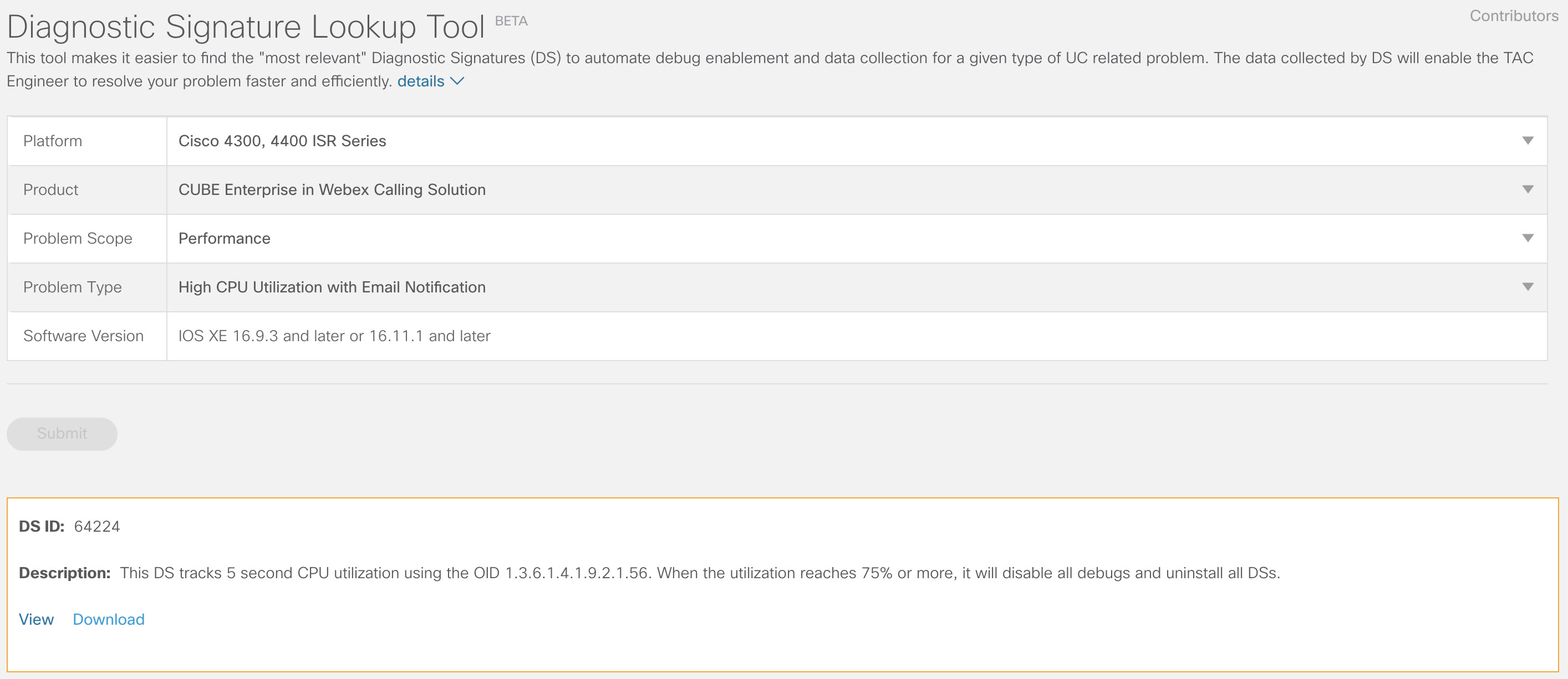
This DS tracks CPU utilization for five seconds using the SNMP OID 1.3.6.1.4.1.9.2.1.56. When the utilization reaches 75% or more, it disables all debugs and uninstalls all diagnostic signatures that are installed in the Local Gateway. Use these steps below to install the signature.
-
Use the show snmp command to enable SNMP. If you do not enable, then configure the snmp-server manager command.
show snmp %SNMP agent not enabled config t snmp-server manager end show snmp Chassis: ABCDEFGHIGK 149655 SNMP packets input 0 Bad SNMP version errors 1 Unknown community name 0 Illegal operation for community name supplied 0 Encoding errors 37763 Number of requested variables 2 Number of altered variables 34560 Get-request PDUs 138 Get-next PDUs 2 Set-request PDUs 0 Input queue packet drops (Maximum queue size 1000) 158277 SNMP packets output 0 Too big errors (Maximum packet size 1500) 20 No such name errors 0 Bad values errors 0 General errors 7998 Response PDUs 10280 Trap PDUs Packets currently in SNMP process input queue: 0 SNMP global trap: enabled -
Download DS 64224 using the following drop-down options in Diagnostic Signatures Lookup Tool:
Field Name
Field Value
Platform
Cisco 4300, 4400 ISR Series or Cisco CSR 1000V Series
Product
CUBE Enterprise in Webex Calling Solution
Problem Scope
Performance
Problem Type
High CPU Utilization with Email Notification.
-
Copy the DS XML file to the Local Gateway flash.
LocalGateway# copy ftp://username:password@<server name or ip>/DS_64224.xml bootflash:The following example shows copying the file from an FTP server to the Local Gateway.
copy ftp://user:pwd@192.0.2.12/DS_64224.xml bootflash: Accessing ftp://*:*@ 192.0.2.12/DS_64224.xml...! [OK - 3571/4096 bytes] 3571 bytes copied in 0.064 secs (55797 bytes/sec) -
Install the DS XML file in the Local Gateway.
call-home diagnostic-signature load DS_64224.xml Load file DS_64224.xml success -
Use the show call-home diagnostic-signature command to verify that the signature is successfully installed. The status column should have a “registered” value.
show call-home diagnostic-signature
Current diagnostic-signature settings:
Diagnostic-signature: enabled
Profile: CiscoTAC-1 (status: ACTIVE)
Downloading  URL(s):  https://tools.cisco.com/its/service/oddce/services/DDCEService
Environment variable:
ds_email: username@gmail.com
Download DSes:
DS ID
DS Name
Revision
Status
Last Update (GMT+00:00)
64224
DS_LGW_CPU_MON75
0.0.10
Registered
2020-11-07 22:05:33
When triggered, this signature uninstalls all running DSs including itself. If necessary, reinstall DS 64224 to continue monitoring high CPU utilization on the Local Gateway.
Monitoring SIP trunk registration
This DS checks for unregistration of a Local Gateway SIP Trunk with Webex Calling cloud every 60 seconds. Once the unregistration event is detected, it generates an email and syslog notification and uninstalls itself after two unregistration occurrences. Use the steps below to install the signature:
-
Download DS 64117 using the following drop-down options in Diagnostic Signatures Lookup Tool:
Field Name
Field Value
Platform
Cisco 4300, 4400 ISR Series or Cisco CSR 1000V Series
Product
CUBE Enterprise in Webex Calling Solution
Problem Scope
SIP-SIP
Problem Type
SIP Trunk Unregistration with Email Notification.
-
Copy the DS XML file to the Local Gateway.
copy ftp://username:password@<server name or ip>/DS_64117.xml bootflash: -
Install the DS XML file in the Local Gateway.
call-home diagnostic-signature load DS_64117.xml Load file DS_64117.xml success LocalGateway# -
Use the show call-home diagnostic-signature command to verify that the signature is successfully installed. The status column must have a “registered” value.
Monitoring abnormal call disconnects
This DS uses SNMP polling every 10 minutes to detect abnormal call disconnect with SIP errors 403, 488 and 503. If the error count increment is greater than or equal to 5 from the last poll, it generates a syslog and email notification. Please use the steps below to install the signature.
-
Use the show snmp command to check whether SNMP is enabled. If it is not enabled, configure the snmp-server manager command.
show snmp %SNMP agent not enabled config t snmp-server manager end show snmp Chassis: ABCDEFGHIGK 149655 SNMP packets input 0 Bad SNMP version errors 1 Unknown community name 0 Illegal operation for community name supplied 0 Encoding errors 37763 Number of requested variables 2 Number of altered variables 34560 Get-request PDUs 138 Get-next PDUs 2 Set-request PDUs 0 Input queue packet drops (Maximum queue size 1000) 158277 SNMP packets output 0 Too big errors (Maximum packet size 1500) 20 No such name errors 0 Bad values errors 0 General errors 7998 Response PDUs 10280 Trap PDUs Packets currently in SNMP process input queue: 0 SNMP global trap: enabled -
Download DS 65221 using the following options in Diagnostic Signatures Lookup Tool:
Field Name
Field Value
Platform
Cisco 4300, 4400 ISR Series or Cisco CSR 1000V Series
Product
CUBE Enterprise in Webex Calling Solution
Problem Scope
Performance
Problem Type
SIP abnormal call disconnect detection with Email and Syslog Notification.
-
Copy the DS XML file to the Local Gateway.
copy ftp://username:password@<server name or ip>/DS_65221.xml bootflash: -
Install the DS XML file in the Local Gateway.
call-home diagnostic-signature load DS_65221.xml Load file DS_65221.xml success -
Use the show call-home diagnostic-signature command to verify that the signature is successfully installed. The status column must have a “registered” value.
Install diagnostic signatures to troubleshoot a problem
Use Diagnostic Signatures (DS) to resolve issues quickly. Cisco TAC engineers have authored several signatures that enable the necessary debugs that are required to troubleshoot a given problem, detect the problem occurrence, collect the right set of diagnostic data and transfer the data automatically to the Cisco TAC case. Diagnostic Signatures (DS) eliminate the need to manually check for the problem occurrence and makes troubleshooting of intermittent and transient issues a lot easier.
You can use the Diagnostic Signatures Lookup Tool to find the applicable signatures and install them to self-solve a given issue or you can install the signature that is recommended by the TAC engineer as part of the support engagement.
Here is an example of how to find and install a DS to detect the occurrence “%VOICE_IEC-3-GW: CCAPI: Internal Error (call spike threshold): IEC=1.1.181.1.29.0" syslog and automate diagnostic data collection using the following steps:
-
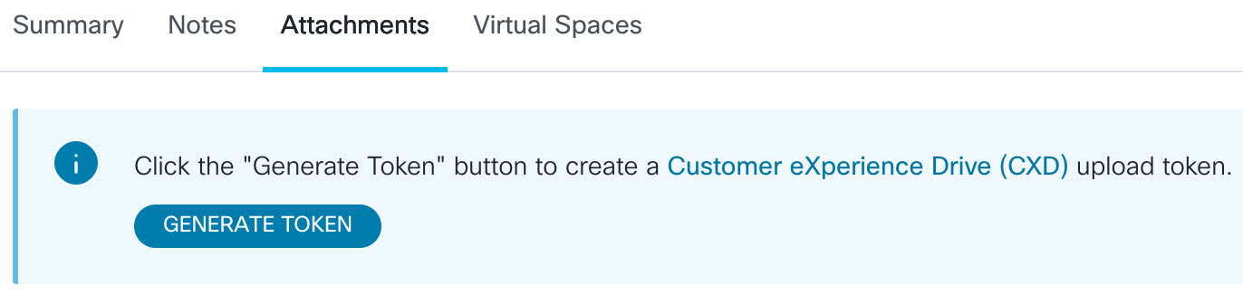
Configure an additional DS environment variable ds_fsurl_prefix which is the Cisco TAC file server path (cxd.cisco.com) to which the collected diagnostics data are uploaded. The username in the file path is the case number and the password is the file upload token which can be retrieved from Support Case Manager in the following command. The file upload token can be generated in the Attachments section of the Support Case Manager, as needed.
configure terminal
call-home
diagnostic-signature
LocalGateway(cfg-call-home-diag-sign)environment ds_fsurl_prefix "scp://<case number>:<file upload token>@cxd.cisco.com"
end
Example:
call-home diagnostic-signature environment ds_fsurl_prefix " environment ds_fsurl_prefix "scp://612345678:abcdefghijklmnop@cxd.cisco.com" -
Ensure that SNMP is enabled using the show snmp command. If it is not enabled, configure the snmp-server manager command.
show snmp %SNMP agent not enabled config t snmp-server manager end -
Ensure to install the High CPU monitoring DS 64224 as a proactive measure to disable all debugs and diagnostics signatures during the time of high CPU utilization. Download DS 64224 using the following options in Diagnostic Signatures Lookup Tool:
Field Name
Field Value
Platform
Cisco 4300, 4400 ISR Series or Cisco CSR 1000V Series
Product
CUBE Enterprise in Webex Calling Solution
Problem Scope
Performance
Problem Type
High CPU Utilization with Email Notification.
-
Download DS 65095 using the following options in Diagnostic Signatures Lookup Tool:
Field Name
Field Value
Platform
Cisco 4300, 4400 ISR Series or Cisco CSR 1000V Series
Product
CUBE Enterprise in Webex Calling Solution
Problem Scope
Syslogs
Problem Type
Syslog - %VOICE_IEC-3-GW: CCAPI: Internal Error (Call spike threshold): IEC=1.1.181.1.29.0
-
Copy the DS XML files to the Local Gateway.
copy ftp://username:password@<server name or ip>/DS_64224.xml bootflash: copy ftp://username:password@<server name or ip>/DS_65095.xml bootflash: -
Install the High CPU monitoring DS 64224 and then DS 65095 XML file in the Local Gateway.
call-home diagnostic-signature load DS_64224.xml Load file DS_64224.xml success call-home diagnostic-signature load DS_65095.xml Load file DS_65095.xml success -
Verify that the signature is successfully installed using the show call-home diagnostic-signature command. The status column must have a “registered” value.
show call-home diagnostic-signature
Current diagnostic-signature settings:
Diagnostic-signature: enabled
Profile: CiscoTAC-1 (status: ACTIVE)
Downloading  URL(s):  https://tools.cisco.com/its/service/oddce/services/DDCEService
Environment variable:
           ds_email: username@gmail.com
           ds_fsurl_prefix: scp://612345678:abcdefghijklmnop@cxd.cisco.com
Downloaded DSes:
DS ID
DS Name
Revision
Status
Last Update (GMT+00:00)
64224
00:07:45
DS_LGW_CPU_MON75
0.0.10
Registered
2020-11-08
65095
00:12:53
DS_LGW_IEC_Call_spike_threshold
0.0.12
Registered
2020-11-08
Verify diagnostic signatures execution
In the following command, the “Status” column of the show call-home diagnostic-signature command changes to “running” while the Local Gateway executes the action defined within the signature. The output of show call-home diagnostic-signature statistics is the best way to verify whether a diagnostic signature detects an event of interest and executes the action. The “Triggered/Max/Deinstall” column indicates the number of times the given signature has triggered an event, the maximum number of times it is defined to detect an event and whether the signature deinstalls itself after detecting the maximum number of triggered events.
show call-home diagnostic-signature
Current diagnostic-signature settings:
Diagnostic-signature: enabled
Profile: CiscoTAC-1 (status: ACTIVE)
Downloading  URL(s):  https://tools.cisco.com/its/service/oddce/services/DDCEService
Environment variable:
           ds_email: carunach@cisco.com
           ds_fsurl_prefix: scp://612345678:abcdefghijklmnop@cxd.cisco.com
Downloaded DSes:
|
DS ID |
DS Name |
Revision |
Status |
Last Update (GMT+00:00) |
|---|---|---|---|---|
| 64224 |
DS_LGW_CPU_MON75 |
0.0.10 |
Registered |
2020-11-08 00:07:45 |
|
65095 |
DS_LGW_IEC_Call_spike_threshold |
0.0.12 |
Running |
2020-11-08 00:12:53 |
show call-home diagnostic-signature statistics
|
DS ID |
DS Name |
Triggered/Max/Deinstall |
Average Run Time (seconds) |
Max Run Time (seconds) |
|---|---|---|---|---|
| 64224 |
DS_LGW_CPU_MON75 |
0/0/N |
0.000 |
0.000 |
|
65095 |
DS_LGW_IEC_Call_spike_threshold |
1/20/Y |
23.053 |
23.053 |
The notification email that is sent during diagnostic signature execution contains key information such as issue type, device details, software version, running configuration, and show command outputs that are relevant to troubleshoot the given problem.
Uninstall diagnostic signatures
Use Diagnostic signatures for troubleshooting purposes are typically defined to uninstall after detection of some problem occurrences. If you want to uninstall a signature manually, retrieve the DS ID from the output of the show call-home diagnostic-signature command and run the following command:
call-home diagnostic-signature deinstall <DS ID>
Example:
call-home diagnostic-signature deinstall 64224
New signatures are added to Diagnostics Signatures Lookup Tool periodically, based on issues that are commonly observed in deployments. TAC currently doesn’t support requests to create new custom signatures.
For better management of Cisco IOS XE Gateways, we recommend that you enroll and manage the gateways through the Control Hub. It is an optional configuration. When enrolled, you can use the configuration validation option in the Control Hub to validate your Local Gateway configuration and identify any configuration issues. Currently, only registration-based trunks support this functionality.
For more information, refer the following:
This section describes how to configure a Cisco Unified Border Element (CUBE) as a Local Gateway for Webex Calling using a certificate-based, mutual TLS (mTLS) SIP trunk. The first part of this document illustrates how to configure a simple PSTN gateway. In this case, all calls from the PSTN are routed to Webex Calling and all calls from Webex Calling are routed to the PSTN. The following image highlights this solution and the high-level call routing configuration that will be followed.
In this design, the following principal configurations are used:
-
voice class tenants: Used to create trunk specific configurations.
-
voice class uri: Used to classify SIP messages for the selection of an inbound dial-peer.
-
inbound dial-peer: Provides treatment for inbound SIP messages and determines the outbound route using a dial-peer group.
-
dial-peer group: Defines the outbound dial-peers used for onward call routing.
-
outbound dial-peer: Provides treatment for outbound SIP messages and routes them to the required target.
When connecting an on-premises Cisco Unified Communications Manager solution with Webex Calling, you can use the simple PSTN gateway configuration as a baseline for building the solution illustrated in the following diagram. In this case, a Unified Communications Manager provides centralized routing and treatment of all PSTN and Webex Calling calls.
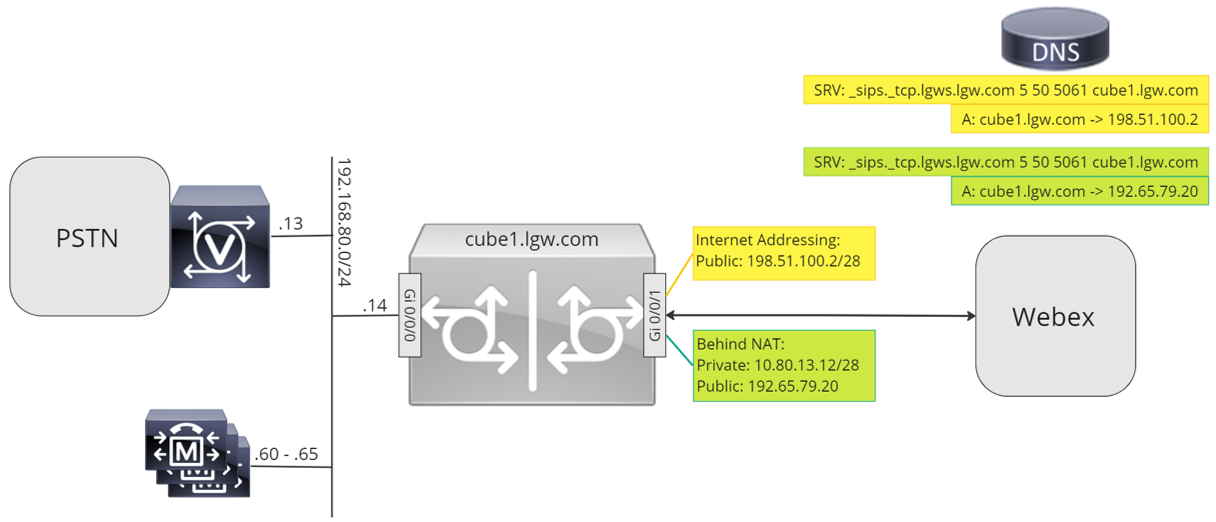
Throughout this document, the host names, IP addresses, and interfaces illustrated in the following image are used. Options are provided for public or private (behind NAT) addressing. SRV DNS records are optional, unless load balancing across multiple CUBE instances.
Use the configuration guidance in the rest of this document to complete your Local Gateway configuration as follows:
Baseline configuration
The first step in preparing your Cisco router as a Local Gateway for Webex Calling is to build a baseline configuration that secures your platform and establishes connectivity.
-
All certificate-based Local Gateway deployments require Cisco IOS XE 17.9.1a or later versions. Cisco IOS XE 17.12.2 or later is recommended. For the recommended versions, see the Cisco Software Research page. Search for the platform and select one of the suggested releases.
-
ISR4000 series routers must be configured with both Unified Communications and Security technology licenses.
-
Catalyst Edge 8000 series routers fitted with voice cards or DSPs require DNA Advantage licensing. Routers without voice cards or DSPs require a minimum of DNA Essentials licensing.
-
For high-capacity requirements, you may also require a High Security (HSEC) license and additional throughput entitlement.
Refer to Authorization Codes for further details.
-
-
Build a baseline configuration for your platform that follows your business policies. In particular, configure and verify the following:
-
NTP
-
ACLs
-
User authentication and remote access
-
DNS
-
IP routing
-
IP addresses
-
-
The network toward Webex Calling must use an IPv4 address. Local Gateway Fully Qualified Domain Names (FQDN) or Service Record (SRV) addresses configured in the Control Hub must resolve to a public IPv4 address on the internet.
-
All SIP and media ports on the Local Gateway interface facing Webex must be accessible from the internet, either directly or via static NAT. Ensure that you update your firewall accordingly.
-
Follow the detailed configuration steps provided below to install a signed certificate on the Local Gateway:
-
A public Certificate Authority (CA) as detailed in What Root Certificate Authorities are Supported for Calls to Cisco Webex Audio and Video Platforms? must sign the device certificate.
-
Certificates containing only Server Authentication Extended Key Usage (EKU) are supported. Webex Calling does not validate or enforce the presence of Client Authentication EKU during TLS handshake establishment.
Some third-party Session Border Controllers (SBC) may enforce strict EKU validation and could reject certificates that do not include Client Authentication EKU. In such cases, ensure the SBC is configured to accept certificates with Server Authentication EKU only or to disable strict EKU validation (if supported).
-
The certificate subject Common Name (CN), or one of the Subject Alternative Names (SAN) must be the same as the FQDN configured in the Control Hub.
When purchasing a certificate with Common Name (CN) or Subject Alternative Name (SAN), ensure that the certificate uses only lowercase letters. In Control Hub configuration, all FQDN entries are automatically converted to lowercase, and any mismatch in letter casing between the FQDN and the certificate will prevent successful trunk registration.
For example:
-
If a configured trunk in the Control Hub of your organization has cube1.lgw.com:5061 as FQDN of the Local Gateway, then the CN or SAN in the router certificate must contain cube1.lgw.com.
-
If a configured trunk in the Control Hub of your organization has lgws.lgw.com as the SRV address of the Local Gateway(s) reachable from the trunk, then the CN or SAN in the router certificate must contain lgws.lgw.com. The records that the SRV address resolves to (CNAME, A Record, or IP Address) are optional in SAN.
-
Whether you use an FQDN or SRV for the trunk, the contact address for all new SIP dialogs from your Local Gateway must use the name configured in the Control Hub.
-
-
-
Upload the Cisco root CA bundle to the Local Gateway. This bundle includes the CA root certificate used to verify the Webex platform.
Configuration
| 1 |
Ensure that you assign valid and routable IP addresses to any Layer 3 interfaces, for example:
|
| 2 |
Protect STUN credentials on the router using symmetric encryption. Configure the primary encryption key and encryption type as follows: |
| 3 |
Create an encryption trustpoint with a certificate for your domain, signed by a supported Certificate Authority (CA). |
| 4 |
Provide the certificate of the intermediate signing CA to authenticate your host certificate. Enter the following exec or configuration command:
|
| 5 |
Import the signed host certificate using the following exec or configuration command:
|
| 6 |
Enable TLS1.2 exclusivity and specify the default trustpoint to use for voice applications using the following configuration commands:
|
| 7 |
Install the Cisco root CA bundle, which includes the IdenTrust Commercial Root CA 1 certificate used by Webex Calling. Use the crypto pki trustpool import clean url url command to download the root CA bundle from the specified URL, and to clear the current CA trustpool, then install the new bundle of certificates: If you need to use a proxy for access to the internet using HTTPS, add the following configuration before importing the CA bundle: ip http client proxy-server yourproxy.com proxy-port 80 |
| 1 |
Create a CUBE certificate-based PSTN trunk for an existing location in the Control Hub. For more information, see Configure trunks, route groups, and dial plans for Webex Calling. Make a note of the trunk information on creating the trunk. These details, as highlighted in the following illustration is used in the configuration steps in this guide.
|
| 2 |
Enter the following commands to configure CUBE as a Webex Calling Local Gateway: Here's an explanation of the fields for the configuration:
Enables Cisco Unified Border Element (CUBE) features on the platform. allow-connections sip to sipEnable CUBE basic SIP back to back user agent functionality. For more information, see Allow connections. By default, T.38 fax transport is enabled. For more information, see fax protocol t38 (voice-service). Enables STUN (Session Traversal of UDP through NAT) globally. These global stun commands are only required when deploying your Local Gateway behind NAT.
For more information, see stun flowdata agent-id and stun flowdata shared-secret. asymmetric payload fullConfigures SIP asymmetric payload support for both DTMF and dynamic codec payloads. For more information on this command, see asymmetric payload. early-offer forcedForces the Local Gateway to send SDP information in the initial INVITE message instead of waiting for acknowledgment from the neighboring peer. For more information on this command, see early-offer. sip-profiles inboundEnables CUBE to use SIP profiles to modify messages as they are received. Profiles are applied through dial-peers or tenants. |
| 3 |
Configure voice class codec 100 allowing G.711 codecs only for all trunks. This simple approach is suitable for most deployments. If necessary, add additional codec types supported by both originating and terminating systems to the list. More complex solutions involving transcoding using DSP modules are supported, but not included in this guide. Here's an explanation of the fields for the configuration: voice class codec 100Used to only allow preferred codecs for SIP trunk calls. For more information, see voice class codec. |
| 4 |
Configure voice class stun-usage 100 to enable ICE on the Webex Calling trunk. (This step is not applicable for Webex for Government) Here's an explanation of the fields for the configuration: stun usage ice liteUsed to enable ICE-Lite for all Webex Calling facing dial-peers to allow media-optimization whenever possible. For more information, see voice class stun usage and stun usage ice lite. The stun usage firewall-traversal flowdata command is only required when deploying your Local Gateway behind NAT. Media optimization is negotiated wherever possible. If a call requires cloud media services, such as recording, the media cannot be optimized. |
| 5 |
Configure the media encryption policy for Webex traffic. (This step is not applicable for Webex for Government) Here's an explanation of the fields for the configuration: voice class srtp-crypto 100Specifies SHA1_80 as the only SRTP cipher-suite CUBE offers in the SDP in offer and answer messages. Webex Calling only supports SHA1_80. For more information, see voice class srtp-crypto. |
| 6 |
Configure FIPS-compliant GCM ciphers (This step is applicable only for Webex for Government). Here's an explanation of the fields for the configuration: voice class srtp-crypto 100Specifies GCM as the cipher-suite that CUBE offers. It is mandatory to configure GCM ciphers for Local Gateway for Webex for Government. |
| 7 |
Configure a pattern to uniquely identify calls to a Local Gateway trunk based on its destination FQDN or SRV: Here's an explanation of the fields for the configuration: voice class uri 100 sipDefines a pattern to match an incoming SIP invite to an incoming trunk dial-peer. When entering this pattern, use the trunk FQDN or SRV configured in the Control Hub for the trunk. During tenant-side configuration of certificate-based trunks for Webex Calling, use only SRV-based Webex Calling Edge address on the Local Gateway. FQDNs are no longer supported. |
| 8 |
Configure SIP message manipulation profiles. If your gateway is configured with a public IP address, configure a profile as follows or skip to the next step if you are using NAT. In this example, cube1.lgw.com is the FQDN configured for the Local Gateway: Here's an explanation of the fields for the configuration: rules 10 and 20To allow Webex to authenticate messages from your local gateway, the 'Contact' header in a SIP request and responses messages must contain the value provisioned for the trunk in the Control Hub. This will either be the FQDN of a single host, or the SRV name used for a cluster of devices. |
| 9 |
If your gateway is configured with a private IP address behind static NAT, configure the inbound and outbound SIP profiles as follows. In this example, cube1.lgw.com is the FQDN configured for the Local Gateway, "10.80.13.12" is the interface IP address facing Webex Calling and "192.65.79.20" is the NAT public IP address.
SIP profiles for outbound messages to Webex
Calling
Here's an explanation of the fields for the configuration: rules 10 and 20To allow Webex to authenticate messages from your local gateway, the 'Contact' header in SIP request and responses messages must contain the value provisioned for the trunk in the Control Hub. This will either be the FQDN of a single host, or the SRV name used for a cluster of devices. rules 30 to 81Convert private address references to the external public address for the site, allowing Webex to correctly interpret and route subsequent messages. SIP profile for inbound messages from Webex CallingHere's an explanation of the fields for the configuration: rules 10 to 80Convert public address references to the configured private address, allowing CUBE to process the messages from Webex. For more information, see voice class sip-profiles. United States or Canadian PSTN provider can offer the Caller ID verification for Spam and fraud calls, with the additional configuration mentioned in the Spam or fraud call indication in Webex Calling article. |
| 10 |
Configure a SIP Options keepalive with header modification profile. Here's an explanation of the fields for the configuration: voice class sip-options-keepalive 100Configures a keepalive profile and enters voice class configuration mode. You can configure the time (in seconds) at which an SIP Out of Dialog Options Ping is sent to the dial-target when the heartbeat connection to the endpoint is in UP or Down status. This keepalive profile is triggered from the dial-peer configured towards Webex. To ensure that the contact headers include the SBC fully qualified domain name, SIP profile 115 is used. Rules 30, 40, and 50 are required only when the SBC is configured behind static NAT. In this example, cube1.lgw.com is the FQDN selected for the Local Gateway and if static NAT is used, "10.80.13.12" is the SBC interface IP address towards Webex Calling and "192.65.79.20" is the NAT public IP address. |
| 11 |
Configure Webex Calling trunk: |
| 12 |
(Optional) To configure network devices such as CUBE and to forward Session Initiation Protocol (SIP) headers that the device doesn't process, use these commands. These commands enable the device to pass through unsupported SIP headers, including geo-location headers and PIDF-LO (Presence Information Data Format - Location Object), on the local gateway. This functionality supports Nomadic E-911 services by ensuring that critical location information is preserved and forwarded correctly. |
Having built a trunk towards Webex Calling above, use the following configuration to create a non-encrypted trunk towards a SIP based PSTN provider:
If your Service Provider offers a secure PSTN trunk, you may follow a similar configuration as detailed above for the Webex Calling trunk. CUBE supports secure call routing.
If you are using a TDM / ISDN PSTN trunk, skip to the next section Configure Local Gateway with TDM PSTN trunk.
To configure TDM interfaces for PSTN call legs on the Cisco TDM-SIP Gateways, see Configuring ISDN PRI.
| 1 |
Configure the following voice class uri to identify inbound calls from the PSTN trunk: Here's an explanation of the fields for the configuration: voice class uri 200 sipDefines a pattern to match an incoming SIP invite to an incoming trunk dial-peer. When entering this pattern, use the IP address of your IP PSTN gateway. For more information, see voice class uri. |
| 2 |
Configure the following IP PSTN dial-peer: Here's an explanation of the fields for the configuration: Defines a VoIP dial-peer with a tag of 200 and gives a meaningful description for ease of management and troubleshooting. For more information, see dial-peer voice. destination-pattern BAD.BADA dummy destination pattern is required when routing outbound calls using an inbound dial-peer group. Any valid destination pattern may be used in this case. For more information, see destination-pattern (interface). session protocol sipv2Specifies that this dial-peer handles SIP call legs. For more information, see session protocol (dial peer). session target ipv4: 192.168.80.13Specifies the target address for calls sent to the PSTN provider. This could be either an IP address or DNS host name. For more information, see session target (VoIP dial peer). incoming uri via 200Specifies the voice class used to match incoming calls to this dial-peer using the INVITE VIA header URI. For more information, see incoming url.
voice-class sip asserted-id pai
(Optional) Turns on P-Asserted-Identity header processing and controls how this is used for the PSTN trunk. If this command is used, the calling party identity provided from the incoming dial-peer is used for the outgoing From and P-Asserted-Identity headers. If this command is not used, the calling party identity provided from the incoming dial-peer is used for the outgoing From and Remote-Party-ID headers. For more information, see voice-class sip asserted-id.
bind control
source-interface
GigabitEthernet0/0/0
Configures the source interface and associated IP address for messages sent to the PSTN. For more information, see bind. bind media source-interface GigabitEthernet0/0/0Configures the source interface and associated IP address for media sent to PSTN. For more information, see bind. voice-class codec 100Configures the dial-peer to use the common codec filter list 100. For more information, see voice-class codec. dtmf-relay rtp-nteDefines RTP-NTE (RFC2833) as the DTMF capability expected on the call leg. For more information, see DTMF Relay (Voice over IP). no vadDisables voice activity detection. For more information, see vad (dial peer). |
| 3 |
If you are configuring your Local Gateway to only route calls between Webex Calling and the PSTN, add the following call routing configuration. If you are configuring your Local Gateway with a Unified Communications Manager platform, skip to the next section. |
Having built a trunk towards Webex Calling, use the following configuration to create a TDM trunk for your PSTN service with loop-back call routing to allow media optimization on the Webex call leg.
If you do not require IP media optimization, follow the configuration steps for a SIP PSTN trunk. Use a voice port and POTS dial-peer (as shown in Steps 2 and 3) instead of the PSTN VoIP dial-peer.
| 1 |
The loop-back dial-peer configuration uses dial-peer groups and call routing tags to ensure that calls pass correctly between Webex and the PSTN, without creating call routing loops. Configure the following translation rules that will be used to add and remove the call routing tags: Here's an explanation of the fields for the configuration: voice translation-ruleUses regular expressions defined in rules to add or remove call routing tags. Over-decadic digits (‘A’) are used to add clarity for troubleshooting. In this configuration, the tag added by translation-profile 100 is used to guide calls from Webex Calling towards the PSTN via the loopback dial-peers. Similarly, the tag added by translation-profile 200 is used to guide calls from the PSTN towards Webex Calling. Translation-profiles 11 and 12 remove these tags before delivering calls to the Webex and PSTN trunks respectively. This example assumes that called numbers from Webex Calling are presented in +E.164 format. Rule 100 removes the leading + to maintain a valid called number. Rule 12 then adds a national or international routing digit(s) when removing the tag. Use digits that suit your local ISDN national dial plan. If Webex Calling presents numbers in national format, adjust rules 100 and 12 to simply add and remove the routing tag respectively. For more information, see voice translation-profile and voice translation-rule. |
| 2 |
Configure TDM voice interface ports as required by the trunk type and protocol used. For more information, see Configuring ISDN PRI. For example, the basic configuration of a Primary Rate ISDN interface installed in NIM slot 2 of a device might include the following: |
| 3 |
Configure the following TDM PSTN dial-peer: Here's an explanation of the fields for the configuration: Defines a VoIP dial-peer with a tag of 200 and gives a meaningful description for ease of management and troubleshooting. For more information, see dial-peer voice. destination-pattern BAD.BADA dummy destination pattern is required when routing outbound calls using an inbound dial-peer group. Any valid destination pattern may be used in this case. For more information, see destination-pattern (interface). translation-profile incoming 200Assigns the translation profile that will add a call routing tag to the incoming called number. direct-inward-dialRoutes the call without providing a secondary dial-tone. For more information, see direct-inward-dial. port 0/2/0:15The physical voice port associated with this dial-peer. |
| 4 |
To enable media optimization of IP paths for Local Gateways with TDM-IP call flows, you can modify the call routing by introducing a set of internal loop-back dial-peers between Webex Calling and PSTN trunks. Configure the following loop-back dial-peers. In this case, all incoming calls will be routed initially to dial-peer 10 and from there to either dial-peer 11 or 12 based on the applied routing tag. After removal of the routing tag, calls will be routed to the outbound trunk using dial-peer groups. Here's an explanation of the fields for the configuration: Defines a VoIP dial-peer and gives a meaningful description for ease of management and troubleshooting. For more information, see dial-peer voice. translation-profile incoming 11Applies the translation profile defined earlier to remove the call routing tag before passing to the outbound trunk. destination-pattern BAD.BADA dummy destination pattern is required when routing outbound calls using an inbound dial-peer group. For more information, see destination-pattern (interface). session protocol sipv2Specifies that this dial-peer handles SIP call legs. For more information, see session protocol (dial peer). session target ipv4: 192.168.80.14Specifies the local router interface address as the call target to loop-back. For more information, see session target (voip dial peer). bind control source-interface GigabitEthernet0/0/0Configures the source interface and associated IP address for messages sent through the loop-back. For more information, see bind. bind media source-interface GigabitEthernet0/0/0Configures the source interface and associated IP address for media sent through the loop-back. For more information, see bind. dtmf-relay rtp-nteDefines RTP-NTE (RFC2833) as the DTMF capability expected on the call leg. For more information, see DTMF Relay (Voice over IP). codec g711alaw Forces all PSTN calls to use G.711. Select a-law or u-law to match the companding method used by your ISDN service. no vadDisables voice activity detection. For more information, see vad (dial peer). |
| 5 |
Add the following call routing configuration: This concludes your Local Gateway configuration. Save the configuration and reload the
platform if this is the first time CUBE features are configured.
|
The PSTN-Webex Calling configuration in the previous sections may be modified to include additional trunks to a Cisco Unified Communications Manager (UCM) cluster. In this case, all calls are routed via Unified CM. Calls from UCM on port 5060 are routed to the PSTN and calls from port 5065 are routed to Webex Calling. The following incremental configurations may be added to include this calling scenario.
| 1 |
Configure the following voice class URIs: |
| 2 |
Configure the following DNS records to specify SRV routing to Unified CM hosts: IOS XE uses these records for locally determining target UCM hosts and ports. With this configuration, it is not required to configure records in your DNS system. If you prefer to use your DNS, then these local configurations are not required. Here's an explanation of the fields for the configuration: The following command creates a DNS SRV resource record. Create a record for each UCM host and trunk: ip host _sip._udp.pstntocucm.io srv 2 1 5060 ucmsub5.mydomain.com _sip._udp.pstntocucm.io: SRV resource record name 2: The SRV resource record priority 1: The SRV resource record weight 5060: The port number to use for the target host in this resource record ucmsub5.mydomain.com: The resource record target host To resolve the resource record target host names, create local DNS A records. For example: ip host ucmsub5.mydomain.com 192.168.80.65 ip host: Creates a record in the local IOS XE database. ucmsub5.mydomain.com: The A record host name. 192.168.80.65: The host IP address. Create the SRV resource records and A records to reflect your UCM environment and preferred call distribution strategy. |
| 3 |
Configure the following dial-peers: |
| 4 |
Add call routing using the following configurations: |
Diagnostic Signatures (DS) proactively detects commonly observed issues in the Cisco IOS XE-based Local Gateway and generates email, syslog, or terminal message notification of the event. You can also install the DS to automate diagnostics data collection and transfer collected data to the Cisco TAC case to accelerate resolution time.
Diagnostic Signatures (DS) are XML files that contain information about problem trigger events and actions to inform, troubleshoot, and remediate the issue. Use syslog messages, SNMP events and through periodic monitoring of specific show command outputs to define the problem detection logic. The action types include:
-
Collecting show command outputs
-
Generating a consolidated log file
-
Uploading the file to a user provided network location such as HTTPS, SCP, FTP server
TAC engineers author DS files and digitally sign it for integrity protection. Each DS file has the unique numerical ID assigned by the system. Diagnostic Signatures Lookup Tool (DSLT) is a single source to find applicable signatures for monitoring and troubleshooting various problems.
Before you begin:
-
Do not edit the DS file that you download from DSLT. The files that you modify fail installation due to the integrity check error.
-
A Simple Mail Transfer Protocol (SMTP) server you require for the Local Gateway to send out email notifications.
-
Ensure that the Local Gateway is running IOS XE 17.6.1 or higher if you wish to use the secure SMTP server for email notifications.
Prerequisites
Local Gateway running IOS XE 17.6.1 or higher
-
Diagnostic Signatures is enabled by default.
-
Configure the secure email server that you use to send proactive notification if the device is running IOS XE 17.6.1 or higher.
configure terminal call-home mail-server <username>:<pwd>@<email server> priority 1 secure tls end -
Configure the environment variable ds_email with the email address of the administrator to you notify.
configure terminal
call-home
diagnostic-signature
LocalGateway(cfg-call-home-diag-sign)environment ds_email <email address>
end
Install diagnostic signatures for proactive monitoring
Monitoring high CPU utilization
This DS tracks 5-seconds CPU utilization using the SNMP OID 1.3.6.1.4.1.9.2.1.56. When the utilization reaches 75% or more, it disables all debugs and uninstalls all diagnostic signatures that you install in the Local Gateway. Use these steps below to install the signature.
-
Ensure that you enabled SNMP using the command show snmp. If SNMP is not enabled, then configure the snmp-server manager command.
show snmp
%SNMP agent not enabled

config t
snmp-server manager
end

show snmp
Chassis: ABCDEFGHIGK
149655 SNMP packets input
    0 Bad SNMP version errors
    1 Unknown community name
    0 Illegal operation for community name supplied
    0 Encoding errors
    37763 Number of requested variables
    2 Number of altered variables
    34560 Get-request PDUs
    138 Get-next PDUs
    2 Set-request PDUs
    0 Input queue packet drops (Maximum queue size 1000)
158277 SNMP packets output
    0 Too big errors (Maximum packet size 1500)
    20 No such name errors
    0 Bad values errors
    0 General errors
    7998 Response PDUs
    10280 Trap PDUs
Packets currently in SNMP process input queue: 0
SNMP global trap: enabled
Download DS 64224 using the following drop-down options in Diagnostic Signatures Lookup Tool:
copy ftp://username:password@<server name or ip>/DS_64224.xml bootflash:Field Name
Field Value
Platform
Cisco 4300, 4400 ISR Series, or Catalyst 8000V Edge Software
Product
CUBE Enterprise in Webex Calling solution
Problem Scope
Performance
Problem Type
High CPU Utilization with Email Notification
-
Copy the DS XML file to the Local Gateway flash.
copy ftp://username:password@<server name or ip>/DS_64224.xml bootflash:The following example shows copying the file from an FTP server to the Local Gateway.
copy ftp://user:pwd@192.0.2.12/DS_64224.xml bootflash: Accessing ftp://*:*@ 192.0.2.12/DS_64224.xml...! [OK - 3571/4096 bytes] 3571 bytes copied in 0.064 secs (55797 bytes/sec) -
Install the DS XML file in the Local Gateway.
call-home diagnostic-signature load DS_64224.xml Load file DS_64224.xml success -
Use the show call-home diagnostic-signature command to verify that the signature is successfully installed. The status column must have a “registered” value.
show call-home diagnostic-signature
Current diagnostic-signature settings:
 Diagnostic-signature: enabled
 Profile: CiscoTAC-1 (status: ACTIVE)
 Downloading  URL(s):  https://tools.cisco.com/its/service/oddce/services/DDCEService
 Environment variable:
           ds_email: username@gmail.com
Download DSes:
DS ID
DS Name
Revision
Status
Last Update (GMT+00:00)
64224
DS_LGW_CPU_MON75
0.0.10
Registered
2020-11-07 22:05:33
When triggered, this signature uninstalls all running DSs including itself. If necessary, please reinstall DS 64224 to continue monitoring high CPU utilization on the Local Gateway.
Monitoring abnormal call disconnects
This DS uses SNMP polling every 10 minutes to detect abnormal call disconnect with SIP errors 403, 488 and 503. If the error count increment is greater than or equal to 5 from the last poll, it generates a syslog and email notification. Please use the steps below to install the signature.
-
Ensure that SNMP is enabled using the command show snmp. If SNMP is not enabled, configure the snmp-server manager command.
show snmp %SNMP agent not enabled config t snmp-server manager end show snmp Chassis: ABCDEFGHIGK 149655 SNMP packets input 0 Bad SNMP version errors 1 Unknown community name 0 Illegal operation for community name supplied 0 Encoding errors 37763 Number of requested variables 2 Number of altered variables 34560 Get-request PDUs 138 Get-next PDUs 2 Set-request PDUs 0 Input queue packet drops (Maximum queue size 1000) 158277 SNMP packets output 0 Too big errors (Maximum packet size 1500) 20 No such name errors 0 Bad values errors 0 General errors 7998 Response PDUs 10280 Trap PDUs Packets currently in SNMP process input queue: 0 SNMP global trap: enabled -
Download DS 65221 using the following options in Diagnostic Signatures Lookup Tool:
Field Name
Field Value
Platform
Cisco 4300, 4400 ISR Series, or Catalyst 8000V Edge Software
Product
CUBE Enterprise in Webex Calling Solution
Problem Scope
Performance
Problem Type
SIP abnormal call disconnect detection with Email and Syslog Notification.
-
Copy the DS XML file to the Local Gateway.
copy ftp://username:password@<server name or ip>/DS_65221.xml bootflash: -
Install the DS XML file in the Local Gateway.
call-home diagnostic-signature load DS_65221.xml Load file DS_65221.xml success -
Use the command show call-home diagnostic-signature to verify that the signature is successfully installed. The status column should have a “registered” value.
Install diagnostic signatures to troubleshoot a problem
You can also use Diagnostic Signatures (DS) to resolve issues quickly. Cisco TAC engineers have authored several signatures that enable the necessary debugs that are required to troubleshoot a given problem, detect the problem occurrence, collect the right set of diagnostic data and transfer the data automatically to the Cisco TAC case. This eliminates the need to manually check for the problem occurrence and makes troubleshooting of intermittent and transient issues a lot easier.
You can use the Diagnostic Signatures Lookup Tool to find the applicable signatures and install them to selfsolve a given issue or you can install the signature that is recommended by the TAC engineer as part of the support engagement.
Here is an example of how to find and install a DS to detect the occurrence “%VOICE_IEC-3-GW: CCAPI: Internal Error (call spike threshold): IEC=1.1.181.1.29.0" syslog and automate diagnostic data collection using the following steps:
Configure another DS environment variable ds_fsurl_prefix as the Cisco TAC file server path (cxd.cisco.com) to upload the diagnostics data. The username in the file path is the case number and the password is the file upload token which can be retrieved from Support Case Manager as shown in the following. The file upload token can be generated in the Attachments section of the Support Case Manager, as required.
configure terminal
call-home
diagnostic-signature
LocalGateway(cfg-call-home-diag-sign)environment ds_fsurl_prefix "scp://<case number>:<file upload token>@cxd.cisco.com"
end
Example:
call-home diagnostic-signature environment ds_fsurl_prefix " environment ds_fsurl_prefix "scp://612345678:abcdefghijklmnop@cxd.cisco.com"-
Ensure that SNMP is enabled using the command show snmp. If SNMP not enabled, configure the snmp-server manager command.
show snmp %SNMP agent not enabled config t snmp-server manager end -
We recommend installing the High CPU monitoring DS 64224 as a proactive measure to disable all debugs and diagnostics signatures during the time of high CPU utilization. Download DS 64224 using the following options in Diagnostic Signatures Lookup Tool:
Field Name
Field Value
Platform
Cisco 4300, 4400 ISR Series, or Catalyst 8000V Edge Software
Product
CUBE Enterprise in Webex Calling Solution
Problem Scope
Performance
Problem Type
High CPU Utilization with Email Notification.
-
Download DS 65095 using the following options in Diagnostic Signatures Lookup Tool:
Field Name
Field Value
Platform
Cisco 4300, 4400 ISR Series, or Catalyst 8000V Edge Software
Product
CUBE Enterprise in Webex Calling Solution
Problem Scope
Syslogs
Problem Type
Syslog - %VOICE_IEC-3-GW: CCAPI: Internal Error (Call spike threshold): IEC=1.1.181.1.29.0
-
Copy the DS XML files to the Local Gateway.
copy ftp://username:password@<server name or ip>/DS_64224.xml bootflash: copy ftp://username:password@<server name or ip>/DS_65095.xml bootflash: -
Install the high CPU monitoring DS 64224 and then DS 65095 XML file in the Local Gateway.
call-home diagnostic-signature load DS_64224.xml Load file DS_64224.xml success call-home diagnostic-signature load DS_65095.xml Load file DS_65095.xml success -
Verify that the signature is successfully installed using show call-home diagnostic-signature. The status column should have a “registered” value.
show call-home diagnostic-signature
Current diagnostic-signature settings:
 Diagnostic-signature: enabled
 Profile: CiscoTAC-1 (status: ACTIVE)
 Downloading  URL(s):  https://tools.cisco.com/its/service/oddce/services/DDCEService
 Environment variable:
           ds_email: username@gmail.com
           ds_fsurl_prefix: scp://612345678:abcdefghijklmnop@cxd.cisco.com
Downloaded DSes:
DS ID
DS Name
Revision
Status
Last Update (GMT+00:00)
64224
00:07:45
DS_LGW_CPU_MON75
0.0.10
Registered
2020-11-08:00:07:45
65095
00:12:53
DS_LGW_IEC_Call_spike_threshold
0.0.12
Registered
2020-11-08:00:12:53
Verify diagnostic signatures execution
In the following command, the “Status” column of the command show call-home diagnostic-signature changes to “running” while the Local Gateway executes the action defined within the signature. The output of show call-home diagnostic-signature statistics is the best way to verify whether a diagnostic signature detects an event of interest and executed the action. The “Triggered/Max/Deinstall” column indicates the number of times the given signature has triggered an event, the maximum number of times it is defined to detect an event and whether the signature deinstalls itself after detecting the maximum number of triggered events.
show call-home diagnostic-signature
Current diagnostic-signature settings:
 Diagnostic-signature: enabled
 Profile: CiscoTAC-1 (status: ACTIVE)
 Downloading  URL(s):  https://tools.cisco.com/its/service/oddce/services/DDCEService
 Environment variable:
           ds_email: carunach@cisco.com
           ds_fsurl_prefix: scp://612345678:abcdefghijklmnop@cxd.cisco.com
Downloaded DSes:
|
DS ID |
DS Name |
Revision |
Status |
Last Update (GMT+00:00) |
|---|---|---|---|---|
|
64224 |
DS_LGW_CPU_MON75 |
0.0.10 |
Registered |
2020-11-08 00:07:45 |
|
65095 |
DS_LGW_IEC_Call_spike_threshold |
0.0.12 |
Running |
2020-11-08 00:12:53 |
show call-home diagnostic-signature statistics
|
DS ID |
DS Name |
Triggered/Max/Deinstall |
Average Run Time (seconds) |
Max Run Time (seconds) |
|---|---|---|---|---|
| 64224 |
DS_LGW_CPU_MON75 |
0/0/N |
0.000 |
0.000 |
|
65095 |
DS_LGW_IEC_Call_spike_threshold |
1/20/Y |
23.053 |
23.053 |
The notification email that is sent during Diagnostic Signature execution contains key information such as issue type, device details, software version, running configuration and show command outputs that are relevant to troubleshoot the given problem.
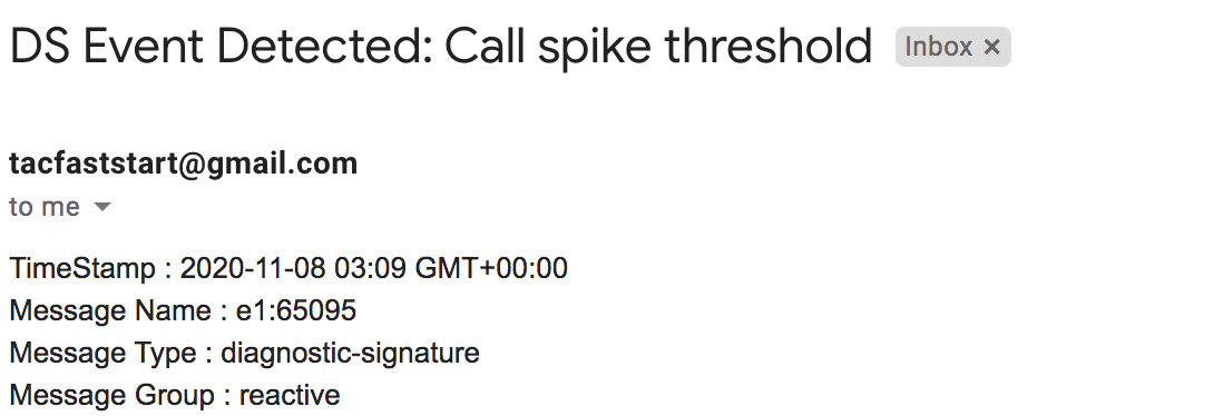
Uninstall diagnostic signatures
Use the diagnostic signatures for troubleshooting purposes are typically defined to uninstall after detection of some problem occurrences. If you wish to uninstall a signature manually, retrieve the DS ID from the output of show call-home diagnostic-signature and run the following command:
call-home diagnostic-signature deinstall <DS ID> Example:
call-home diagnostic-signature deinstall 64224
New signatures are added to the Diagnostics Signatures Lookup Tool periodically, based on issues that are observed in deployments. TAC currently doesn’t support requests to create new custom signatures.


