- Home
- /
- Article

Thanks for your feedback.

Mount your Cisco IP Phone 7800 and 8800 series multiplatform phones on the wall
 In this article
 Feedback?
In areas with no desks, such as kitchens or conference rooms, you can use a wall mount kit to mount a phone to a wall. Check that you have the right wall mount kit for each phone model.
Wall mount kits
Each wall mount is unique to your phone model and cannot be used for another phone. If you are planning to attach your phone to a wall, purchase the wall mount kit specific to your phone.
For part numbers and other additional information, refer to the phone model data sheets:
-
Cisco IP Phone 7800 Series Multiplatform Phones: https://www.cisco.com/c/en/us/products/collaboration-endpoints/ip-phone-7800-series-multiplatform-firmware/datasheet-listing.html
-
Cisco IP Phone 7800 Series (general hardware information): https://www.cisco.com/c/en/us/products/collaboration-endpoints/unified-ip-phone-7800-series/datasheet-listing.html
-
Cisco IP Phone 8800 Series Multiplatform Phones: https://www.cisco.com/c/en/us/products/collaboration-endpoints/ip-phone-8800-series-multiplatform-firmware/datasheet-listing.html
-
Cisco IP Phone 8800 Series (general hardware information): https://www.cisco.com/c/en/us/products/collaboration-endpoints/unified-ip-phone-8800-series/datasheet-listing.html
To check which multiplatform phone model you have, press Applications ![]() and select . The Model number field shows your phone model.
and select . The Model number field shows your phone model.
|
Cisco IP Phone |
Cisco Wall Mount Kit |
|---|---|
|
Cisco IP Phone 7811 |
Spare Wallmount Kit for Cisco IP Phone 7811 (CP-7811-WMK=) |
|
Cisco IP Phone 7821 and 7841 |
Spare Wallmount Kit for Cisco IP Phone 7800 Series (CP-7800-WMK=) |
|
Cisco IP Phone 7861 |
Spare Wallmount Kit for Cisco IP Phone 7861 (CP-7861-WMK=) |
|
Cisco IP Phone |
Cisco Wall Mount Kit |
Notes |
|---|---|---|
|
Cisco IP Phone 8811 and 8841 |
Spare Wallmount Kit for Cisco IP Phone 8800 Series (CP-8800-WMK) |
|
|
Cisco IP Phone 8851 and 8861 |
Spare Wallmount Kit for Cisco IP Phone 8800 Series (CP-8800-WMK) |
This wall mount kit cannot be used with a key expansion module. |
|
Cisco IP Phone 8851 and 8861 |
Spare Wallmount Kit for Cisco IP Phone 8800 Series with Single 36-key Key Expansion Module (CP-8800-BEKEM-WMK) |
This wall mount kit is available for Cisco IP Phone 8851 and 8861 because only these phones support a key expansion module. |
|
Cisco IP Phone 8851 and 8861 |
Spare Wallmount Kit for Cisco IP Phone 8800 Series with Single 28-key Key Expansion Module (lockable) (CP-8800-A-KEM-WMK) |
This wall mount kit is available for Cisco IP Phone 8851 and 8861 that with a key expansion module. It is lockable. |
|
Cisco IP Phone 8845 and 8865 |
Spare Wallmount Kit for Cisco IP Phone 8800 Video Series (CP-8800-VIDEO-WMK=) |
This wall mount kit is available for Cisco IP Phone 8845 and 8865 only. It can be locked, but it cannot be used with a key expansion module. |
Wall mount components
You can attach a wall mount kit to most surfaces, including concrete, brick, or other hard surfaces. But the items in your wall mount kit are for drywall use only. If you mount your phone on other surfaces, obtain the appropriate screws and anchors.
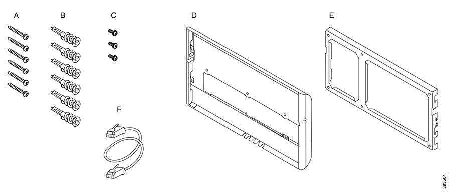
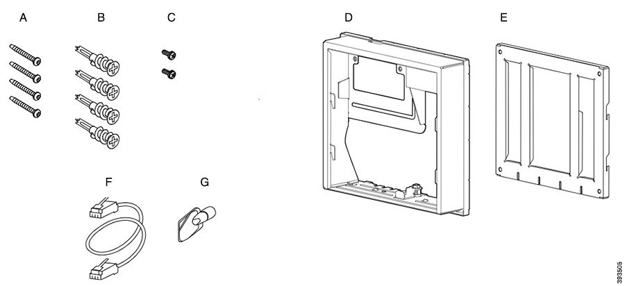
Check and see that you have the correct components before you install your kit. For each phone model, use the table and diagram to check the contents of your wall mount kit.
Spare wall mount kit for Cisco IP Phone 7811
|
Item |
Component |
|---|---|
|
A |
4 M4 x 25-mm Phillips-head screws |
|
B |
4 anchors |
|
C |
2 M3 x 7-mm self-tapping screws |
|
D |
1 wall bracket |
|
E |
1 phone bracket |
|
F |
One 200-mm Ethernet cable |
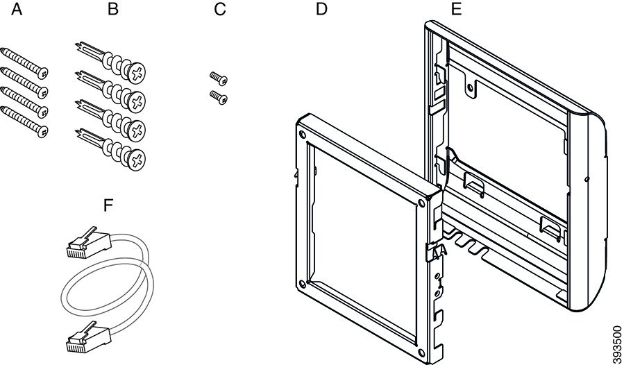
Spare wall mount kit for Cisco IP Phone 7800 series
|
Item |
Component |
|---|---|
|
A |
4 M8-18 x 1.25-inch Phillips-head screws |
|
B |
4 anchors |
|
C |
2 M2.5 x 6-mm machine screws |
|
D |
1 phone bracket |
|
E |
1 wall bracket |
|
F |
One 6-inch Ethernet cable |
Spare wall mount kit for Cisco IP Phone 7861
|
Item |
Component |
|---|---|
|
A |
4 M4 x 25-mm Phillips-head screws |
|
B |
4 anchors |
|
C |
2 M3 x 7-mm self-tapping screws |
|
D |
1 phone bracket |
|
E |
1 wall bracket |
|
F |
One 200-mm Ethernet cable |
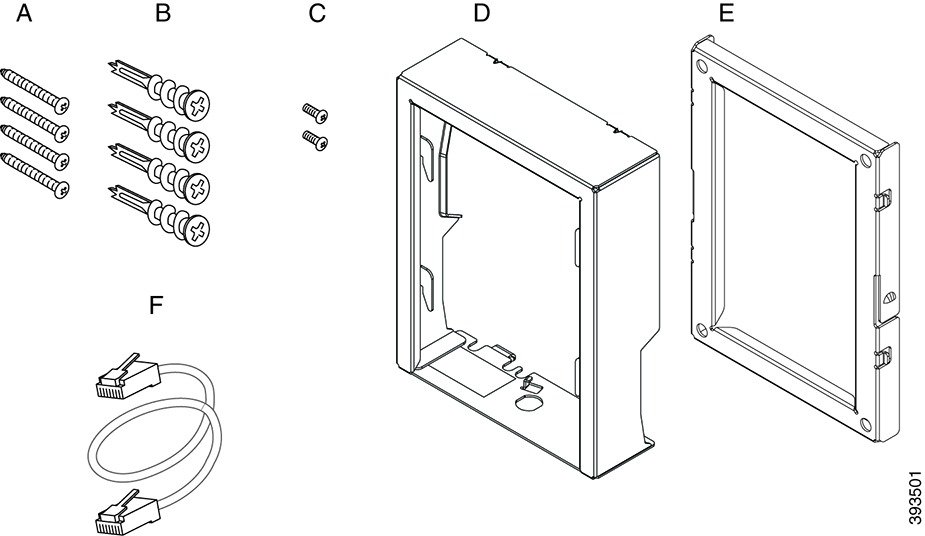
Spare wall mount kit for Cisco IP Phone 8800 series
|
Item |
Component |
|---|---|
|
A |
4 #8-18 x 1.25-inch Phillips-head screws |
|
B |
4 anchors |
|
C |
2 K30x8mm self-tapping screws |
|
D |
1 phone bracket |
|
E |
1 wall bracket |
|
F |
One 6-inch Ethernet cable |

Spare wall mount kit for Cisco IP Phone 8800 series with single 28-key Key expansion module (lockable)
|
Item |
Component |
|---|---|
|
A |
6 #8-18 x 1.25-inch Phillips-head screws |
|
B |
6 anchors |
|
C |
3 K30x8mm self-tapping screws |
|
D |
1 phone bracket |
|
E |
1 wall bracket |
|
F |
One 6-inch Ethernet cable |
|
G |
1 key if the bracket includes the optional lock |
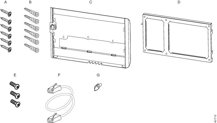
Spare wall mount kit for Cisco IP Phone 8800 series with single 36-key Key expansion module
|
Item |
Component |
|---|---|
|
A |
6 #8-18 x 1.25-inch Phillips-head screws |
|
B |
6 anchors |
|
C |
3 K30x8mm self-tapping screws |
|
D |
1 phone bracket |
|
E |
1 wall bracket |
|
F |
One 6-inch Ethernet cable |
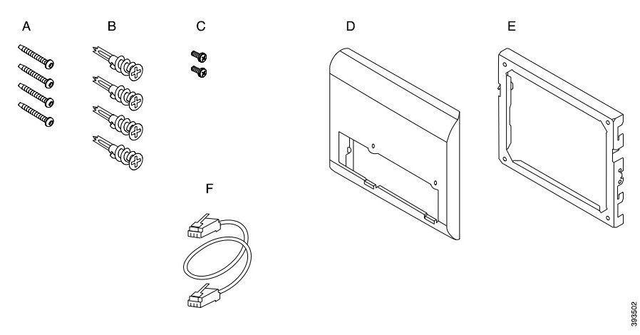
Spare wall mount kit for Cisco IP Phone 8800 Video series
|
Item |
Component |
|---|---|
|
A |
4 #10-12x1-inch Phillips-head screws with |
|
B |
4 anchors |
|
C |
2 #4-40x1/4-inch machine screws |
|
D |
1 phone bracket |
|
E |
1 wall bracket |
|
F |
One 6-inch Ethernet cable |
|
G |
1 key if the bracket includes the optional lock |
|
H |
1 sheet metal screw (not shown) |
Install a spare wall mount kit
Make sure that a working Ethernet connection is available nearby before you install your wall mount kit. If the phone covers the connector, the connector must be flush or recessed to the wall.
Complete your installation in the following order:
-
Attach the wall bracket to the wall
-
Attach the phone bracket to the phone
-
Attach the cables to the phone
-
Attach the phone to the wall bracket
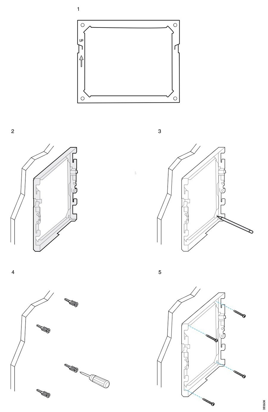
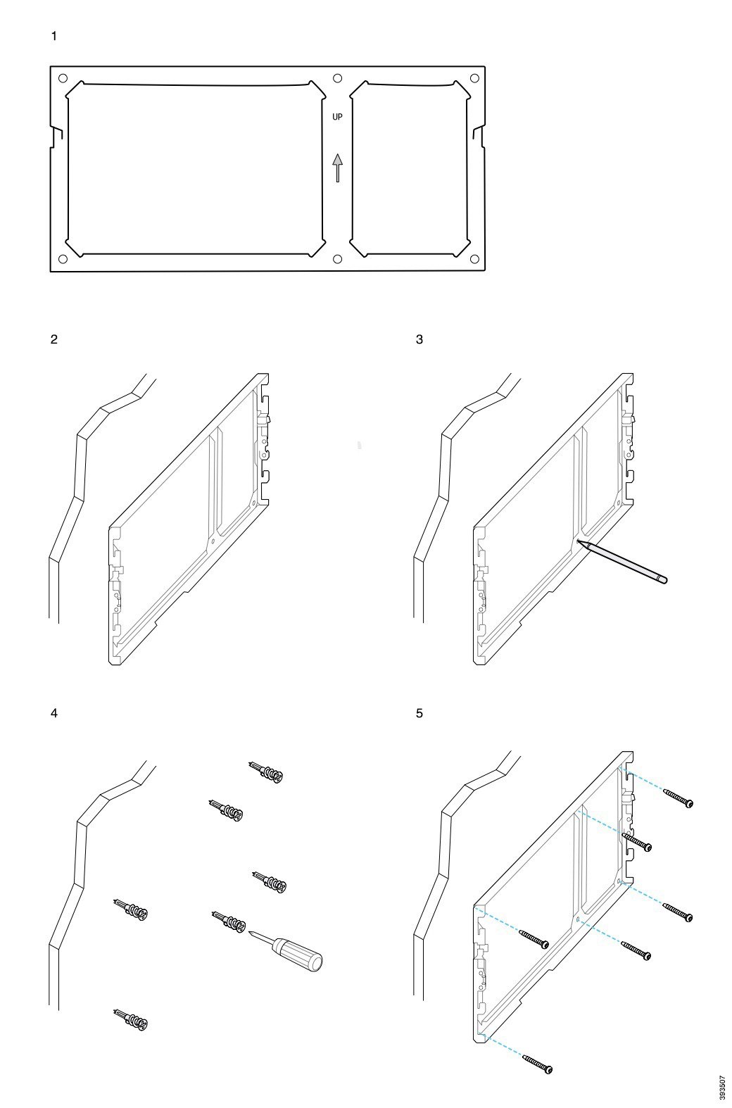
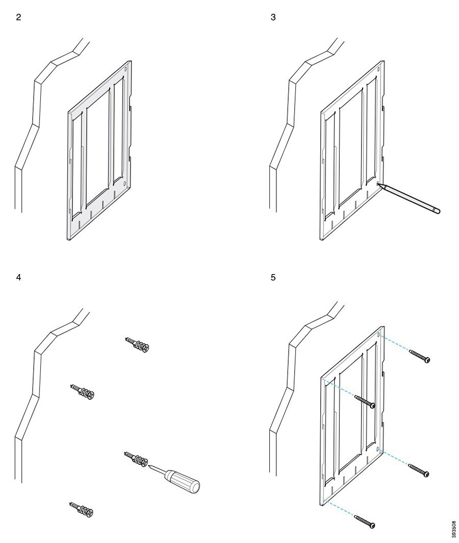
Attach the wall bracket to the wall
Before you begin
Obtain one of each of the following:
-
#2 Phillips-head screwdriver
-
Level
-
Pencil
| 1 |
Hold the bracket against the wall, with the arrow pointing up. |
| 2 |
Use the level to ensure that the bracket is level. |
| 3 |
Use a pencil to mark the screw holes. |
| 4 |
Center the anchor over the pencil mark and use a #2 Phillips-head screwdriver to press the anchor into the wall. Screw the anchor clockwise into the wall until it is seated flush. |
| 5 |
Use the included screws and the #2 Phillips-head screwdriver to attach the bracket to the wall through the anchors. |
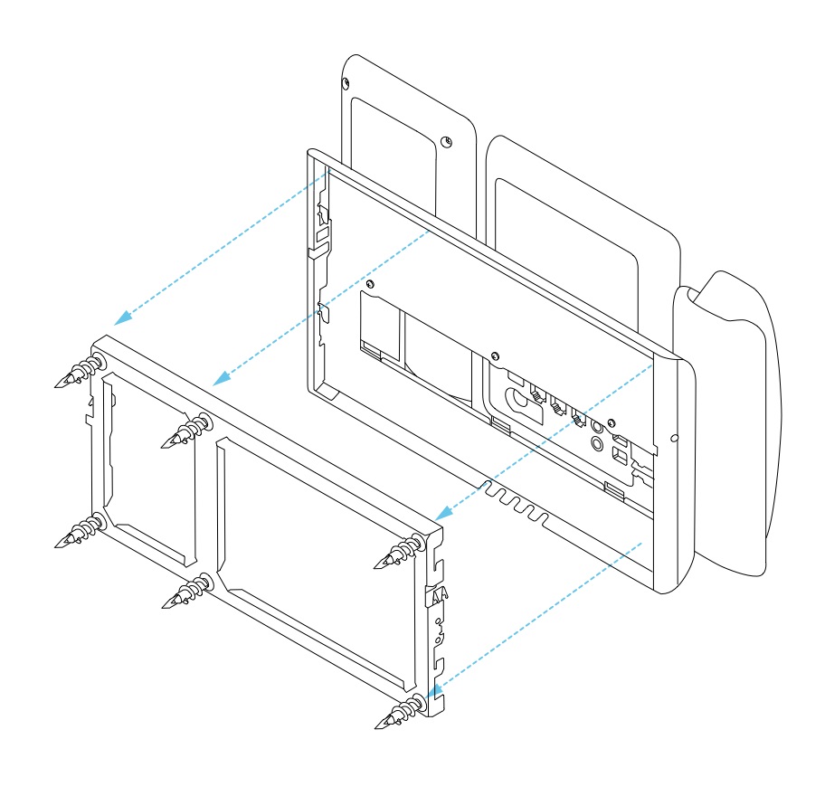
Examples of a wall bracket attached to a wall
The following diagram illustrates attaching a Cisco IP Phone 7800 and 8800 series wall bracket to a wall.
The following diagram illustrates attaching a Cisco IP Phone 8800 series wall bracket with a key expansion module to a wall.
The following diagram illustrates step 2 to step 5 of attaching a Cisco IP Phone 8845 and 8865 series wall bracket to a wall.
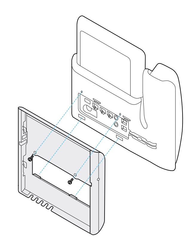
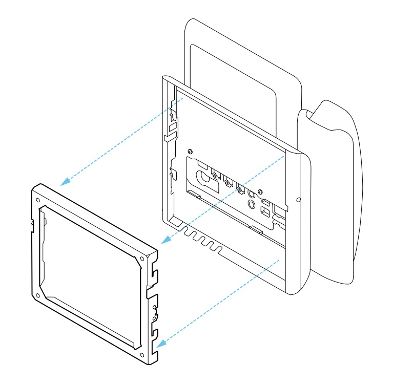
Attach the phone bracket to the phone
Before you attach a phone to the wall, you attach the phone bracket to the phone. The phone bracket attaches the phone to the wall bracket, and it bears the weight of the phone. Ensure that the phone bracket is attached securely to your phone. Because each phone is slightly different, refer to the appropriate example to guide you.
Before you begin
Obtain a #1 Phillips-head screwdriver.
| 1 |
Keep the handset cord or headset cords attached, but remove any other cords from the phone base. |
| 2 |
Attach the phone bracket to the phone. Insert the tabs on the bracket into the mounting tabs on the back of the phone. |
| 3 |
Use the #1 Phillips-head screwdriver to secure the phone bracket to the phone with the self-tapping or the machine screws. |
Examples of a phone bracket attached to a phone
Attach the cables to the phone
Attach the phone cables to your phone before you mount the phone to the wall.
| 1 |
Attach the Ethernet cable to the 10/100/1000 SW network port and to the wall jack. |
| 2 |
(Optional) Attach the cable to the 10/100/1000 computer (PC access) port. |
| 3 |
(Optional) Plug the power cord into the phone and seat the cord in the clips next to the PC port. |
| 4 |
(Optional) If the cables terminate inside the wall bracket, connect the cables to the jacks. |
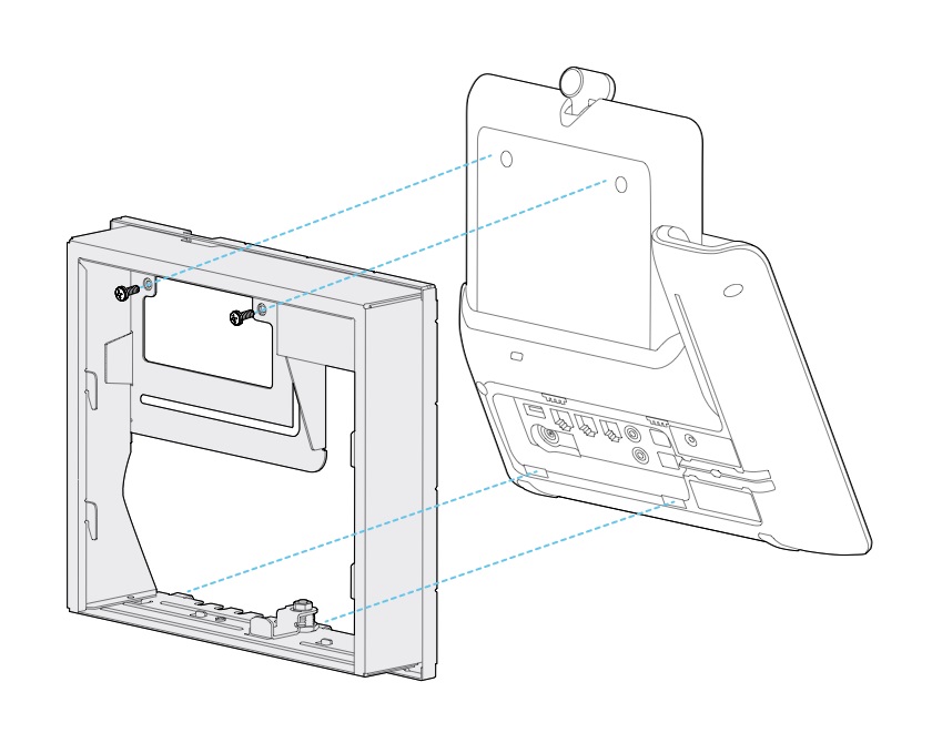
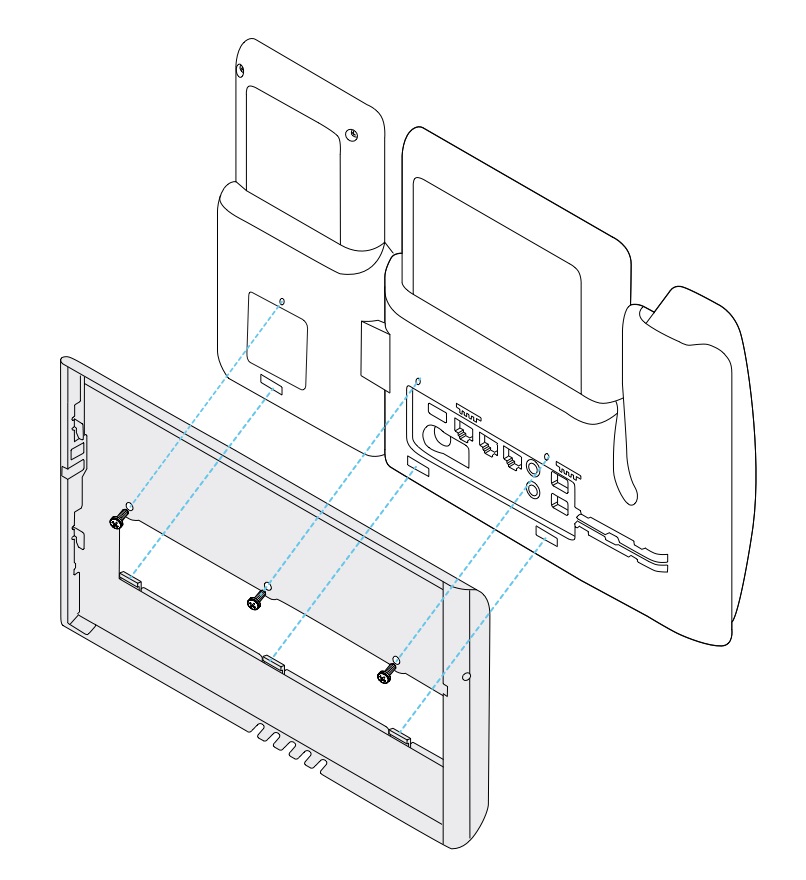
Attach the phone to the wall bracket
After you have installed your wall bracket on the wall, you attach your phone - with the phone bracket to it - to the wall bracket. Ensure that the phone fits securely into the wall bracket. Because each phone is slightly different, refer to the appropriate example to guide you.
| 1 |
Insert the tabs on the top of the wall bracket into the slots on the phone bracket. Cables that terminate outside of the brackets can be positioned in the openings on the bracket bottom, with one cable per opening. |
| 2 |
Press the phone firmly into the wall bracket and slide the phone down. The tabs in the bracket click into position. |
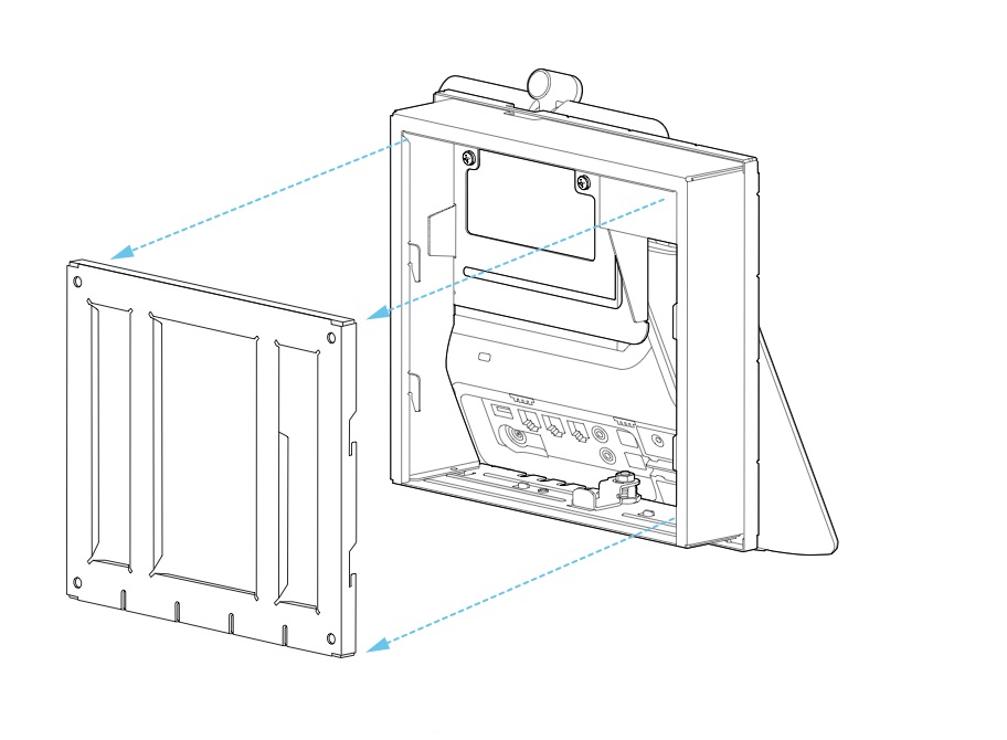
Examples of a Cisco IP Phone attached to the wall bracket
The following diagram illustrates how to attach a Cisco IP Phone 7800 and 8800 series to your wall bracket.
The following diagram illustrates how to attach a Cisco IP Phone 8845 and 8865 to your wall bracket.
The following diagram illustrates how to attach a Cisco IP Phone 8800 series with a key expansion module to your wall bracket.
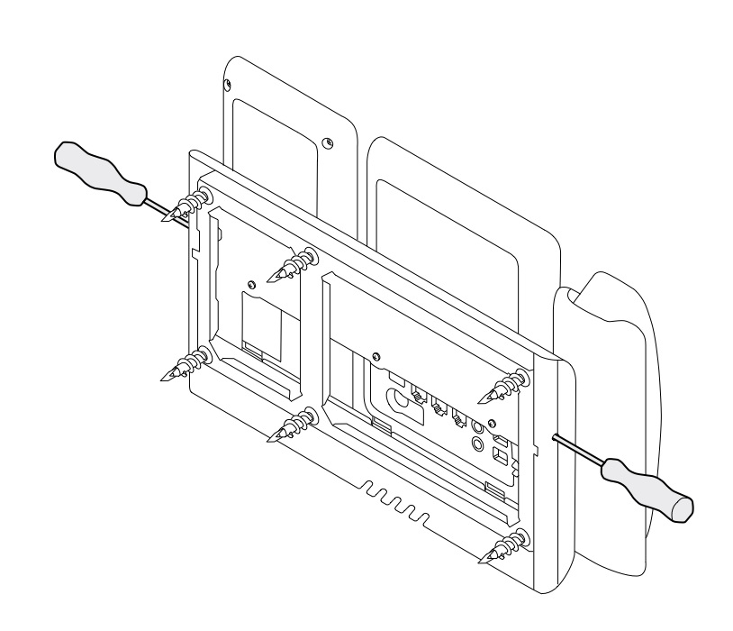
Remove the phone from the wall mount kit
The wall bracket has two tabs that lock the bracket to the phone mounting plate. These tabs must be released before you can remove the phone from the wall mount kit. Because each phone is slightly different, refer to the appropriate example to guide you.
Before you begin
Obtain two Phillips head screwdrivers or other similar devices that have a diameter of 5 millimeters or 3/16 inch.
| 1 |
Insert a screw driver or other device into the left and right holes in the phone mounting plate. Insert to a depth of about 3/4 inch or 2 centimeters. |
| 2 |
Press inwards firmly to disengage the tabs. |
| 3 |
Lift the phone to release it from the wall bracket and pull the phone toward you. |
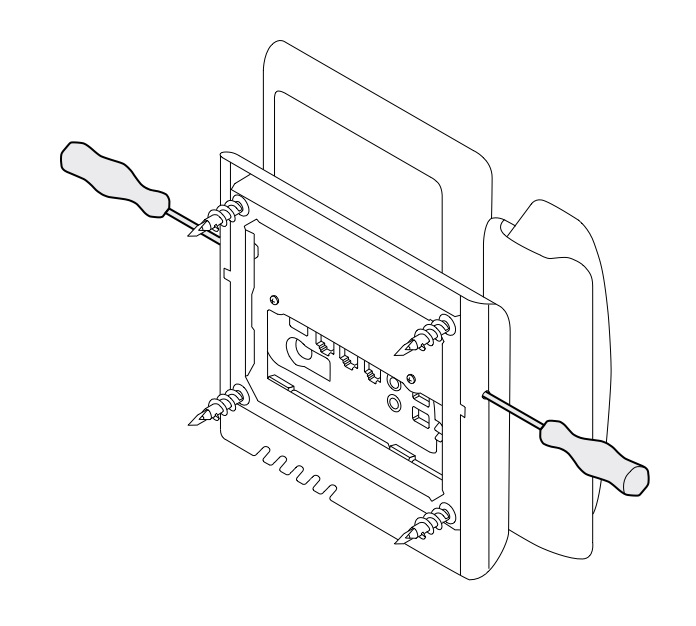
Examples of disengaging the locking tabs
The following diagram illustrates how to disengage the locking tabs on the Cisco IP Phone 7800 and 8800 series.
The following diagram shows how to disengage the locking tabs on the Cisco IP Phone 8800 series with a key expansion module attached.
Adjust the handset rest on your phone
Each Cisco IP Phone comes with a small removeable tab located in the phone cradle. This tab determines how the phone handset sits in the cradle. If your phone is wall mounted or if the handset slips out of the cradle too easily, you may need to adjust how the handset rests on this tab.
Before you begin
Obtain a coin or other similar object with a thickness of about 1.75 mm or 0.069 inch.
| 1 |
Remove the handset from the cradle. Place the edge of the coin in the space between the handset rest and the plastic tab. Remove the tab by quickly rotating the coin counterclockwise. |
| 2 |
Rotate the tab 180 degrees so the ridge points toward you and the smooth back faces down. |
| 3 |
Hold the tab between two fingers, with the corner notches facing you. |
| 4 |
Line up the tab with the slot in the cradle and press the tab evenly into the slot. An extension protrudes from the top of the rotated tab. |
| 5 |
Return the handset to the handset rest. |


