- Home
- /
- Article

Thanks for your feedback.

Implement CUBE high availability as Local Gateway
 In this article
 Feedback?
Local Gateway (LGW) is the exclusive solution for providing on-premises PSTN access to Cisco Webex Calling customers. This document guides you in configuring a Local Gateway using CUBE high availability, with active or standby CUBEs to ensure stateful failover of active calls.
Fundamentals
Prerequisites
Before you deploy Cisco Unified Border Element (CUBE) High Availability (HA) as a local gateway for Webex Calling, make sure you have an in-depth understanding of the following concepts:
-
Layer 2 box-to-box redundancy with CUBE Enterprise for stateful call preservation
The configuration guidelines provided in this article assume a dedicated local gateway platform with no existing voice configuration. If an existing CUBE enterprise deployment is being modified to also utilize the local gateway function for Cisco Webex Calling, pay close attention to the configuration applied to ensure existing call flows and functionalities are not interrupted and make sure you're adhering to CUBE HA design requirements.
Hardware and Software Components
CUBE HA as local gateway requires IOS-XE version 17.9.1 or later and a platform on which both CUBE HA and LGW functions are supported.
The show commands and logs in this article are based on minimum software release of Cisco IOS-XE 17.9.1 implemented on a vCUBE (CSR 8000v).
Reference Material
Here are some detailed CUBE HA configuration guides for various platforms:
-
Cisco ISR 4K and Cisco Catalyst 8K series— https://www.cisco.com/c/en/us/td/docs/ios-xml/ios/voice/cube/ios-xe/config/ios-xe-book/m-cube-ha-isr-g3.html
-
CSR 8000v (vCUBE)— https://www.cisco.com/c/en/us/td/docs/ios-xml/ios/voice/cube/ios-xe/config/ios-xe-book/m-cube-ha-csr.html
-
Cisco Preferred Architecture for Cisco Webex Calling— https://www.cisco.com/c/dam/en/us/td/docs/solutions/CVD/Collaboration/hybrid/AltDesigns/PA-WbxCall.pdf
Webex Calling Solution Overview
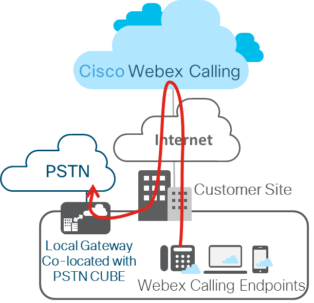
Cisco Webex Calling is a collaboration offering that provides a multi-tenant cloud-based alternative to on-premise PBX phone service with multiple PSTN options for customers.
The Local Gateway deployment (represented below) is the focus of this article. Local gateway (premises-based PSTN) trunk in Webex Calling allows connectivity to a customer-owned PSTN service. It also provides connectivity to an on-premises IP PBX deployment such as Cisco Unified CM. All communication to and from the cloud is secured using TLS transport for SIP and SRTP for media.
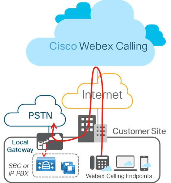
The figure below displays a Webex Calling deployment without any existing IP PBX and is applicable to a single or a multi-site deployment. Configuration outlined in this article is based on this deployment.
Layer 2 Box-to-Box Redundancy
CUBE HA layer 2 box-to-box redundancy uses the Redundancy Group (RG) infrastructure protocol to form an active/standby pair of routers. This pair share the same virtual IP address (VIP) across their respective interfaces and continually exchange status messages. CUBE session information is check-pointed across the pair of routers enabling the standby router to take all CUBE call processing responsibilities over immediately if the active router goes out of service, resulting in stateful preservation of signaling and media.
Check pointing is limited to connected calls with media packets. Calls in transit are not check pointed (for example, a trying or ringing state).
In this article, CUBE HA will refer to CUBE High Availability (HA) Layer 2 Box-to-Box (B2B) redundancy for stateful call preservation.
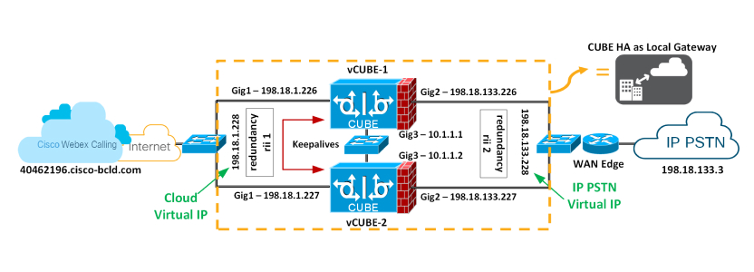
As of IOS-XE 17.9.1, CUBE HA can be deployed as a Local Gateway for Cisco Webex Calling trunk deployments (premises-based PSTN). This article will discuss design considerations and configurations. The figure displays a typical CUBE HA setup as Local Gateway for a Cisco Webex Calling trunk deployment.
Redundancy Group Infra Component
The Redundancy Group (RG) Infra component provides the box-to-box communication infrastructure support between the two CUBEs and negotiates the final stable redundancy state. This component also provides:
-
An HSRP-like protocol that negotiates the final redundancy state for each router by exchanging keepalive and hello messages between the two CUBEs (via the control interface)—GigabitEthernet3 in the figure above.
-
A transport mechanism for checkpointing the signaling and media state for each call from the active to the standby router (via the data interface)—GigabitEthernet3 in the figure above.
-
Configuration and management of the Virtual IP (VIP) interface for the traffic interfaces (multiple traffic interfaces can be configured using the same RG group) – GigabitEthernet 1 and 2 are considered traffic interfaces.
This RG component has to be specifically configured to support voice B2B HA.
Virtual IP (VIP) Address Management for Both Signaling and Media
B2B HA relies on VIP to achieve redundancy. The VIP and associated physical interfaces on both CUBEs in the CUBE HA pair must reside on the same LAN subnet. Configuration of the VIP and binding of the VIP interface to a particular voice application (SIP) are mandatory for voice B2B HA support. External devices such as Unified CM, Webex Calling access SBC, service provider, or proxy, use VIP as the destination IP address for the calls traversing through the CUBE HA routers. Hence, from a Webex Calling point of view, the CUBE HA pairs acts as a single local gateway.
The call signaling and RTP session information of established calls are checkpointed from the active router to the standby router. When the Active router goes down, the Standby router takes over, and continues to forward the RTP stream that was previously routed by the first router.
Calls in a transient state at the time of failover will not be preserved post-switchover. For example, calls that aren't fully established yet or are in the process of being modified with a transfer or hold function. Established calls may be disconnected post-switchover.
The following requirements exist for using CUBE HA as a local gateway for stateful failover of calls:
-
CUBE HA cannot have TDM or analog interfaces co-located
-
Gig1 and Gig2 are referred to as traffic (SIP/RTP) interfaces and Gig3 is Redundancy Group (RG) Control/data interface
-
No more than 2 CUBE HA pairs can be placed in the same layer 2 domain, one with group id 1 and the other with group id 2. If configuring 2 HA pairs with the same group id, RG Control/Data interfaces needs to belong to different layer 2 domains (vlan, separate switch)
-
Port channel is supported for both RG Control/data and traffic interfaces
-
All signaling/media is sourced from/to the Virtual IP Address
-
Anytime a platform is reloaded in a CUBE-HA relationship, it always boots up as Standby
-
Lower address for all the interfaces (Gig1, Gig2, Gig3) should be on the same platform
-
Redundancy Interface Identifier, rii should be unique to a pair/interface combination on the same Layer 2
-
Configuration on both the CUBEs must be identical including physical configuration and must be running on the same type of platform and IOS-XE version
-
Loopback interfaces cannot be used as bind as they are always up
-
Multiple traffic (SIP/RTP) interfaces (Gig1, Gig2) require interface tracking to be configured
-
CUBE-HA is not supported over a crossover cable connection for the RG-control/data link (Gig3)
-
Both platforms must be identical and be connected via a physical Switch across all likewise interfaces for CUBE HA to work, i.e. GE0/0/0 of CUBE-1 and CUBE-2 must terminate on the same switch and so on.
-
Cannot have WAN terminated on CUBEs directly or Data HA on either side
-
Both Active/Standby must be in the same data center
-
It is mandatory to use separate L3 interface for redundancy (RG Control/data, Gig3). i.e interface used for traffic cannot be used for HA keepalives and checkpointing
-
Upon failover, the previously active CUBE goes through a reload by design, preserving signaling and media
Configure redundancy on both CUBEs
You must configure layer 2 box-to-box redundancy on both CUBEs intended to be used in an HA pair to bring up virtual IPs.
| 1 |
Configure interface tracking at a global level to track the status of the interface.
Track CLI is used in RG to track the voice traffic interface state so that the active route will quite its active role after the traffic interface is down. | ||
| 2 |
Configure an RG for use with VoIP HA under the application redundancy sub-mode.
Here's an explanation of the fields used in this configuration:
| ||
| 3 |
Enable box-to-box redundancy for the CUBE application. Configure the RG from the
previous step under
redundancy-group 1—Adding and removing this command requires a reload for the updated configuration to take effect. We'll reload the platforms after all the configuration has been applied. | ||
| 4 |
Configure the Gig1 and Gig2 interfaces with their respective virtual IPs as shown below and apply the redundancy interface identifier (rii)
Here's an explanation of the fields used in this configuration:
| ||
| 5 |
Save the configuration of the first CUBE and reload it. The platform to reload last is always the Standby.
After VCUBE-1 boots up completely, save the configuration of VCUBE-2 and reload it.
| ||
| 6 |
Verify that the box-to-box configuration is working as expected. Relevant output is highlighted in bold. We reloaded VCUBE-2 last and as per the design considerations; the platform to reload last will always be Standby. Next, proceed with the Local Gateway configuration (Registration-based or Certificate-based) on both the HA CUBEs. See Configure Local Gateway on Cisco IOS XE for Webex Calling. |


