- Home
- /
- Article

Thanks for your feedback.

Webex Calling Configuration Workflow
 In this article
 Feedback?
Get your bearings with all of the information available about Webex Calling, whether you're a partner, an administrator, or a user. Use the links provided here to help you get started using all of the services and features available with Webex Calling.
Overview of Webex Calling
Imagine being able to use enterprise-grade cloud Calling, mobility, and PBX features, along with Webex App for Messaging and meetings and Calling from a Webex Calling soft client or Cisco device. That's exactly what Webex Calling has to offer you.
Webex Calling provides the following features and benefits:
-
Calling subscriptions for telephony users and common areas.
-
Secure and reliable cloud services delivered by trusted regional service providers
-
Webex App access for every user, adding rich unified communications and team collaboration services.
-
Webex Meetings as an optional, integrated add-on to provide the premium meetings experiences that enterprise users expect.
-
Public Switch Telephony Networks (PSTN) access to let your users dial numbers outside the organization. The service is provided through an existing enterprise infrastructure
-
Local gateway without on-premises IP PBX
-
Existing Unified CM call environment
-
Partner or Cisco provided PSTN options
-
-
Tier 1 support provided by your partner, next level support provided by Cisco
Control Hub is a web-based management portal that integrates with Webex Calling to streamline your orders and configuration, and centralize your management of the bundled offer—Webex Calling, Webex App, and Webex Meetings.
|
Feature |
Description |
|---|---|
|
Auto Attendant |
You can add greetings, set up menus, and route calls to an answering service, a hunt group, a voicemail box, or a real person. You can create a 24-hour schedule or provide different options when your business is open or closed. You can even route calls based on caller ID attributes to create VIP lists or handle calls from certain area codes differently. |
|
Call Queue |
You can set up a call queue when you can't answer incoming calls. You can provide callers with an automated answer, comfort messages, and music on hold until someone can answer their call. |
|
Call Pickup |
You can enhance teamwork and collaboration by creating a call pickup group so users can answer another users calls. When you add users to a call pickup group and a group member is away or busy, another member can answer their calls. |
|
Call Park |
You can turn on call park to allow users to place a call on hold and pick it up from another phone. |
|
Hunt Group |
You may want to set up hunt groups in the following scenarios:
|
|
Paging Group |
You can create a paging group so that users can send an audio message to a person, a department, or a team. When someone sends a message to a paging group, the message plays on all devices in the group. |
|
Receptionist Client |
Help support the needs of your front-office personnel by providing them with a full set of call control options, large-scale line monitoring, call queuing, multiple directory options and views, Outlook integration, and more. |
|
Feature |
Description |
|---|---|
|
Anonymous Call Rejection |
Users can reject incoming calls with blocked caller IDs. |
|
Business Continuity |
If users' phones are not connected to the network for reason such as power outage, network issues, and so on, then the users can forward incoming calls to a specific phone number. |
|
Call Forwarding |
Users can forward incoming calls to another phone. |
|
Call Forwarding Selective |
Users can forward calls at specific times from specific callers. This setting will take precedence over Call Forwarding. |
|
Call Notify |
Users can send themselves an email when they receive a call according to predefined criteria such as phone number or date and time. |
|
Call Waiting |
Users can allow answering of additional incoming calls. |
|
Do Not Disturb |
Users can temporarily let all calls go directly to voicemail. |
|
Office Anywhere |
Users can use their selected phones ("Locations") as an extension of their business phone number and dial plan. |
|
Priority Alert |
Users can ring their phones with a distinctive ring when predefined criteria are met, such as phone number or date and time. |
|
Remote Office |
Users can make calls from a remote phone and have it appear from their business line. In addition, any incoming calls to their business line rings on this remote phone. |
|
Selective Call Acceptance |
Users can accept calls at specific times from specific callers. |
|
Selective Call Rejection |
Users can reject calls at specific times from specific callers. |
|
Sequential Ring |
Ring up to 5 devices one after another for incoming calls. |
|
Simultaneous Ring |
Ring users' and others (“call recipients“) numbers at the same time for incoming calls. |
Provisioning Services, Devices, and Users in Control Hub, Cross-Launch to Detailed Configuration in Calling Admin Portal
Control Hub ( https://admin.webex.com) is a management portal that integrates with Webex Calling to streamline your orders and configuration, and centralize your management of the bundled offer—Webex Calling, Webex App, and Meetings.
Control Hub is the central point for provisioning all services, devices, and users. You can do first time setup of your calling service, register MPP phones to the cloud (using MAC address), configure users by associating devices, adding numbers, services, calling features, and so on. Also, from Control Hub, you can cross-launch to the Calling Admin Portal.
User Experience
Users have access to the following interfaces:
-
Webex Calling application—Soft-client for calling that's branded by Cisco. For more information, see Explore the New Cisco Webex Calling App.
-
Webex Settings ( https://settings.webex.com)—Interface where users can set preferences for the profile, download Webex App, and cross-launch into the Calling User Portal for Calling settings. For more information, see Change Your Cisco Webex Settings.
-
Webex App—Application included in the subscription as a Cisco-branded Team Messaging client. For more information, see Get Started with the Cisco Webex App.
-
Webex Meetings—Optional application added on as a Meetings solution. For more information, see Webex Meetings.
Customer Administrators
As a customer administrator on a trial or paid subscription to Webex Calling, you can set up your organization in Control Hub by adding locations, licenses, phone numbers, Calling features, users, and Workspaces (Room Devices that register to the Webex cloud). You can manage all these components from there as well.
-
For guidance, see the Configuration Guide for Cisco Webex Calling Customers.
-
For more information on the Webex Calling offer, see Cisco Webex Calling in the Cisco Collaboration Flex Plan for End Customers Data Sheet
Partners
As a partner service provider, you can brand, market, and sell Webex Calling to your customers. You can set up and extend trials, deploy services for your customers, and create and provision orders for your customers.
-
For guidance, see the Configuration Guide for Cisco Webex Calling Customers (Early Partner Enrollment Program).
-
For more partner resources, see the Webex Calling Sales Connect resources. (Requires partner credentials.)
Availability
See the Webex Calling header in the Where is Cisco Webex Available article for countries where Webex Calling is available for sale.
Take a Tour of Control Hub
Control Hub is your single go-to, web-based interface for managing your organization, managing your users, assigning services, analyzing adoption trends and call quality, and more.
To get your organization up and running, we recommend that you invite a few users to join Webex App by entering their email addresses in Control Hub. Encourage people to use the services you provide, including calling, and to give you feedback about their experience. When you're ready, you can always add more users.
- Control Hub fully supports Mozilla Firefox 66 and later, Google Chrome 89 and later, Microsoft Edge 89 and later, and Apple Safari 15.1 and later.
- Control Hub doesn't support Internet Explorer.
- Control Hub isn’t designed for mobile devices.
Use the information presented below as a high-level summary of what to expect when getting your organization set up with services. See the individual chapters for more detailed information and step-by-step instructions.
Get Started
After your partner creates your account, you'll receive a welcome email. Click the Getting Started link in the email, using Chrome or Firefox to access Control Hub. The link automatically signs you in with your administrator email address. Next, you'll be prompted to create your administrator password.
First Time Wizard for Trials
If your partner has registered you for a trial, the setup wizard automatically starts after you sign in to Control Hub. The wizard walks you through the basic settings to get your organization up and running with Webex Calling, among other services. You can set up and review your Calling settings before finishing the wizard walkthrough.
Review Your Settings
When Control Hub loads, you can review your settings.
Add Users
Now that you have set up your services, you're ready to add people from your company directory. Go to .
If you use Microsoft Active Directory, we recommend that you enable Directory Synchronization first, and then decide how you want to add users. Click Next and follow the instructions to set up Cisco Directory Connector.
Set Up Single Sign On (SSO)
Webex App uses basic authentication. You can choose to set up SSO so that users authenticate with your Enterprise Identity Provider using their Enterprise credentials, rather than a separate password stored and managed in Webex.
Go to , and select Integrate a 3rd-party identity provider.
Assign Services to Users
You must assign services to the users that you've added so that people can start using Webex App.
Go to , and click Export.
In the file you download, add True for the services that you want to assign to each of your users.
Import the completed file, click Add and remove services, and then click Submit. You're now ready to configure calling features, register devices that can be shared in a common place, and register and associate devices with users.
Empower Your Users
Now that you've added users and they've been assigned services, they can start using their supported Multiplatform Phones (MPPs) for Webex Calling and Webex App for messaging and meetings. Encourage them to use Settings as a one-stop shop for access.
Role of the Local Gateway
The local gateway is an enterprise or partner-managed edge device for Public Switch Telephony Network (PSTN) interworking and legacy public branch exchange (PBX) interworking (including Unified CM).
You can use Control Hub to assign a local gateway to a location, after which Control Hub provides parameters that you can configure on the CUBE. These steps register the local gateway with the cloud, and then PSTN service is provided through the gateway to Webex Calling users in a specific location.
To specify and order a Local Gateway, read the Local Gateway ordering guide.
Supported Local Gateway Deployments for Webex Calling
The following basic deployments are supported:
The local gateway can be deployed standalone or in deployments where integration into Cisco Unified Communications Manager is required.
Local Gateway Deployments Without On-Premises IP PBX
Standalone Local Gateway Deployments
This figure shows a Webex Calling deployment without any existing IP PBX and is applicable to a single location or a multi-location deployment.
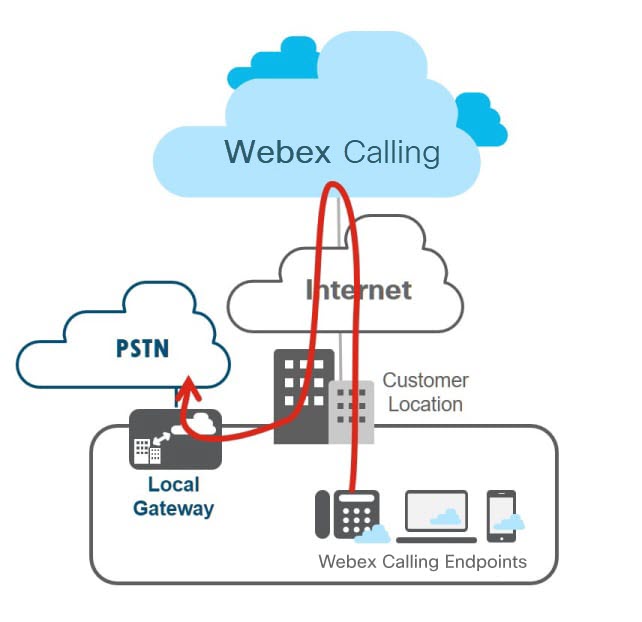
For all calls that do not match your Webex Calling destinations, Webex Calling sends those calls to the local gateway that is assigned to the location for processing. The local gateway routes all calls that are coming from Webex Calling to the PSTN and in the other direction, PSTN to Webex Calling.
The PSTN gateway can be a dedicated platform or coresident with the local gateway. As in the following figure, we recommend the dedicated PSTN gateway variant of this deployment; it may be used if the existing PSTN gateway cannot be used as a Webex Calling local gateway.
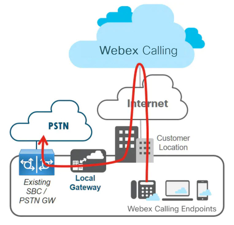
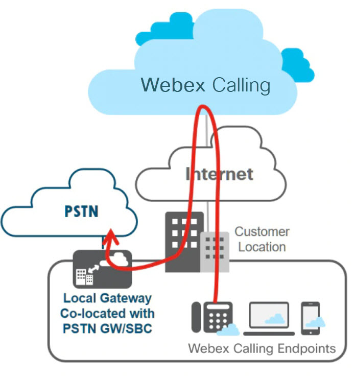
Coresident Local Gateway Deployment
The local gateway can be IP based, connecting to an ITSP using a SIP trunk, or TDM based using an ISDN or analog circuit. The following figure shows a Webex Calling deployment where the local gateway is coresident with the PSTN GW/SBC.
Local Gateway Deployments With On-Premises Unified CM PBX
Integrations with Unified CM are required in the following cases:
-
Webex Calling-enabled locations are added to an existing Cisco UC deployment where Unified CM is deployed as the on-premises call control solution
-
Direct dialing between phones registered to Unified CM and phones in Webex Calling locations is required.
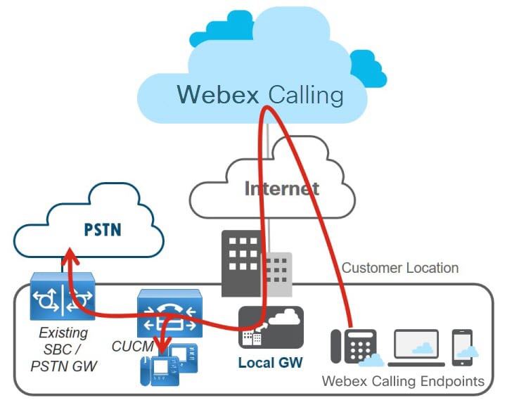
This figure shows a Webex Calling deployment where the customer has an existing Unified CM IP PBX.
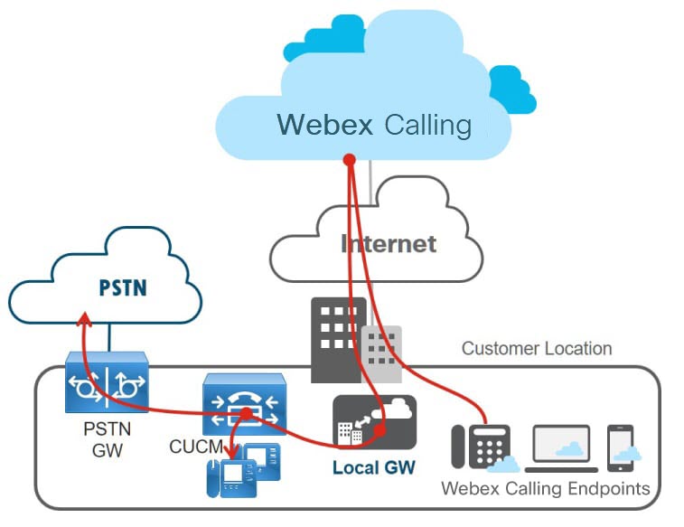
Webex Calling sends calls that do not match the customer’s Webex Calling destinations to the local gateway. This includes PSTN numbers and Unified CM internal extensions, which Webex Calling cannot see. The local gateway routes all calls that are coming from Webex Calling to Unified CM and vice versa. Unified CM then routes incoming calls to local destinations or to the PSTN as per the existing dial plan. The Unified CM dial plan normalizes numbers as +E.164. The PSTN gateway may be a dedicated one or co-resident with the local gateway.
Dedicated PSTN Gateway
The dedicated PSTN gateway variant of this deployment as shown in this diagram is the recommended option and may be used if the existing PSTN gateway cannot be used as a Webex Calling local gateway.
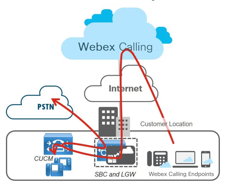
Coresident PSTN Gateway
This figure shows a Webex Calling deployment with a Unified CM where the local gateway is coresident with the PSTN gateway/SBC.
Webex Calling routes all calls that do not match the customer’s Webex Calling destinations to the local gateway that is assigned to the location. This includes PSTN destinations and on-net calls towards Unified CM internal extensions. The local gateway routes all calls to Unified CM. Unified CM then routes calls to locally-registered phones or to the PSTN through the local gateway, which has PSTN/SBC functionality co-located.
Call Routing Considerations
Calls From Webex Calling to Unified CM
The Webex Calling routing logic works like this: if the number that is dialed on a Webex Calling endpoint cannot be routed to any other destination within the same customer in Webex Calling, then the call is sent to the local gateway for further processing. All off-net (outside of Webex Calling) calls are sent to the local gateway.
For a Webex Calling deployment without integration into an existing Unified CM, any off-net call is considered a PSTN call. When combined with Unified CM, an off-net call can still be an on-net call to any destination hosted on Unified CM or a real off-net call to a PSTN destination. The distinction between the latter two call types is determined by the Unified CM and depends on the enterprise dial plan that is provisioned on Unified CM.
The following figure shows a Webex Calling user dialing a national number in the US.
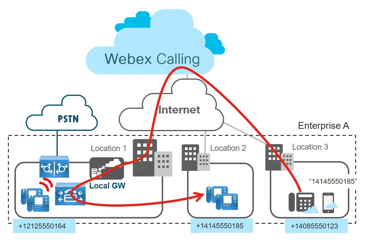
Unified CM now based on the configured dial plan routes the call to a locally registered endpoint on which the called destination is provisioned as directory number. For this the Unified CM dial plan needs to support routing of +E.164 numbers.
Calls From Unified CM to Webex Calling
To enable call routing from Unified CM to Webex Calling on Unified CM a set of routes need to be provisioned to define the set of +E.164 and enterprise numbering plan addresses in Webex Calling.
With these routes in place both the call scenarios shown in the following figure are possible.
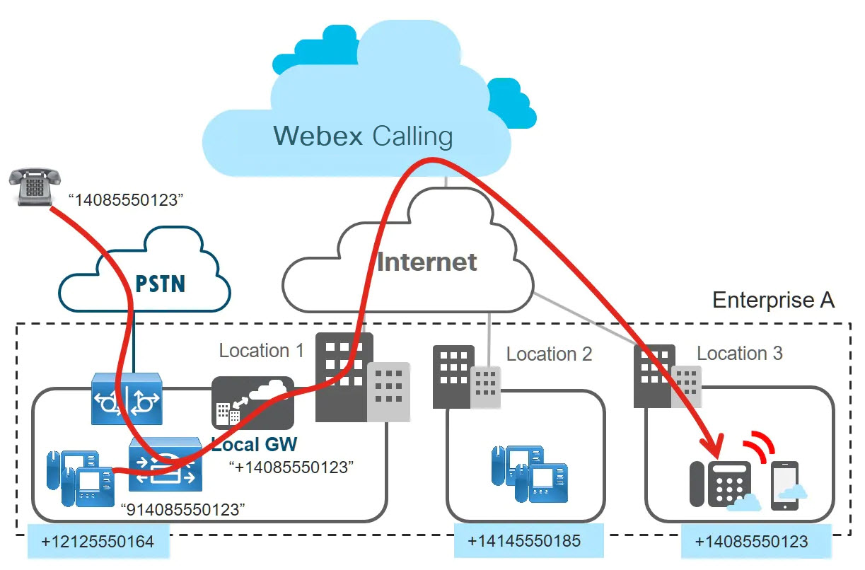
If a caller in the PSTN calls a DID number that is assigned to a Webex Calling device, then the call is handed off to the enterprise through the enterprise’s PSTN gateway and then hits Unified CM. The called address of that call matches one of the Webex Calling routes that is provisioned in Unified CM and the call is sent to the local gateway. (The called address must be in +E.164 format when sent to the local gateway.) The Webex Calling routing logic then makes sure that the call is sent to the intended Webex Calling device, based on DID assignment.
Also, calls originating from Unified CM registered endpoints, targeted at destinations in Webex Calling, are subject to the dial plan that is provisioned on Unified CM. Typically, this dial plan allows the users to use common enterprise dialing habits to place calls. These habits do not necessarily only include +E.164 dialing. Any dialing habit other than +E.164 must be normalized to +E.164 before the calls is sent to the local gateway to allow for correct routing in Webex Calling.
Class of Service (CoS)
Implementing tight class of service restrictions is always recommend for various reasons including avoiding call loops and preventing toll fraud. In the context of integrating Webex Calling Local Gateway with Unified CM class of service we need to consider class of service for:
-
Devices registered with Unified CM
-
Calls coming into Unified CM from the PSTN
-
Calls coming into Unified CM from Webex Calling
Devices registered with Unified CM
Adding the Webex Calling destinations as a new class of destinations to an existing CoS setup is pretty straight forward: permission to call to Webex Calling destinations typically is equivalent to the permission to call on-premise (including inter-site) destinations.
If an enterprise dial-plan already implements an “(abbreviated) on-net inter-site” permission then there already is a partition provisioned on Unified CM which we can use and provision all the known on-net Webex Calling destinations in the same partition.
Otherwise, the concept of “(abbreviated) on-net inter-site” permission does not exist yet, then a new partition (for example “onNetRemote”) needs to be provisioned, the Webex Calling destinations are added to this partition, and finally this new partition needs to be added to the appropriate calling search spaces.
Calls coming into Unified CM from the PSTN
Adding the Webex Calling destinations as a new class of destinations to an existing CoS setup is pretty straight forward: permission to call to Webex Calling destinations typically is equivalent to the permission to call on-premise (including inter-site) destinations.
If an enterprise dial-plan already implements an “(abbreviated) on-net inter-site” permission then there already is a partition provisioned on Unified CM which we can use and provision all the known on-net Webex Calling destinations in the same partition.
Otherwise, the concept of “(abbreviated) on-net inter-site” permission does not exist yet, then a new partition (for example “onNetRemote”) needs to be provisioned, the Webex Calling destinations are added to this partition, and finally this new partition needs to be added to the appropriate calling search spaces.
Calls coming into Unified CM from Webex Calling
Calls coming in from the PSTN need access to all Webex Calling destinations. This requires adding the above partition holding all Webex Calling destinations to the calling search space used for incoming calls on the PSTN trunk. The access to Webex Calling destinations comes in addition to the already existing access.
While for calls from the PSTN access to Unified CM DIDs and Webex Calling DIDs is required calls originating in Webex Calling need access to Unified CM DIDs and PSTN destinations.
This figure compares these two different classes of service for calls from PSTN and Webex Calling. The figure also shows that if the PSTN gateway functionality is collocated with the Local Gateway, then two trunks are required from the combined PSTN GW and Local Gateway to Unified CM: one for calls originating in the PSTN and one for calls originating in Webex Calling. This is driven by the requirement to apply differentiated calling search spaces per traffic type. With two incoming trunks on Unified CM this can easily be achieved by configuring the required calling search space for incoming calls on each trunk.
Dial Plan Integration
This guide assumes an existing installation that is based on best current practices in the “Preferred Architecture for Cisco Collaboration On-Premises Deployments, CVD.” The latest version is available here.
The recommended dial plan design follows the design approach that is documented in the Dial Plan chapter of the latest version of the Cisco Collaboration System SRND available here.
This figure shows an overview of the recommended dial plan design. Key characteristics of this dial plan design include:
-
All directory numbers that are configured on Unified CM are in +E.164 format.
-
All directory numbers reside the same partition (DN) and are marked urgent.
-
Core routing is based on +E.164.
-
All non-+E.164 dialing habits (for example, abbreviated intrasite dialing and PSTN dialing using common dialing habits) are normalized (globalized) to +E.164 using dialing normalization translation patterns.
-
Dialing normalization translation patterns use translation pattern calling search space inheritance; they have the “Use Originator's Calling Search Space” option set.
-
Class of service is implemented using site and class of service-specific calling search spaces.
-
PSTN access capabilities (for example access to international PSTN destinations) are implemented by adding partitions with the respective +E.164 route patterns to the calling search space defining class of service.
Reachability to Webex Calling
To add reachability for Webex Calling destinations to this dial plan, a partition representing all Webex Calling destinations must be created (“Webex Calling”) and a +E.164 route pattern for each DID range in Webex Calling is added to this partition. This route pattern references a route list with only one member: the route group with the SIP trunk to the Local Gateway for calls to Webex Calling. Because all dialed destinations are normalized to +E.164 either using dialing normalization translation patterns for calls originating from Unified CM registered endpoints or inbound called party transformations for calls originating from the PSTN this single set of +E.164 route patterns is enough to achieve reachability for destinations in Webex Calling independent of the dialing habit used.
If, for example, a user dials “914085550165”, then the dialing normalization translation pattern in partition “UStoE164” normalizes this dial string to “+14085550165” which then matches the route pattern for a Webex Calling destination in partition “Webex Calling.” The Unified CM ultimately sends the call to the local gateway.
Add Abbreviated Intersite Dialing
The recommended way to add abbreviated intersite dialing to the reference dial plan is to add dialing normalization translation patterns for all sites under the enterprise numbering plan to a dedicated partition (“ESN”, Enterprise Significant Numbers). These translation patterns intercept dial strings in the format of the enterprise numbering plan and normalize the dialed string to +E.164.
To add enterprise abbreviated dialing to Webex Calling destinations, you add the respective dialing normalization translation pattern for the Webex Calling location to the “Webex Calling” partition (for example “8101XX” in the diagram). After normalization, the call again is sent to Webex Calling after matching the route pattern in the “Webex Calling” partition.
We do not recommend adding the abbreviated dialing normalization translation pattern for Webex Calling calls to the “ESN” partition, because this configuration may create undesired call routing loops.
Protocol Handlers for Calling
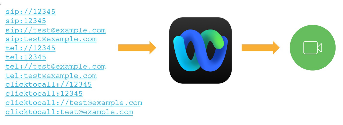
Webex Calling registers the following protocol handlers with the operating system to enable click-to-call functionality from web browsers or other application. The following protocols start an audio or video call in Webex App when it's the default calling application on Mac or Windows:
-
CLICKTOCALL: or CLICKTOCALL://
-
SIP: or SIP://
-
TEL: or TEL://
-
WEBEXTEL: or WEBEXTEL://
Protocol Handlers for Windows
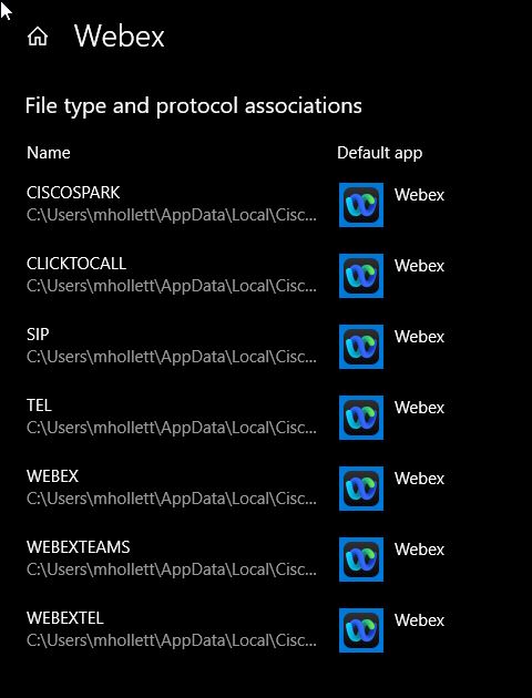
Other apps can register for the protocol handlers before the Webex App. In Windows 10, the system window to ask users to select which app to use to launch the call. The user preference can be remembered if the user checks Always use this app.
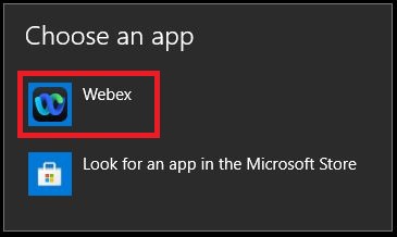
If users need to reset the default calling app settings so that they can pick Webex App, you can instruct them to change the protocol associations for Webex App in Windows 10:
-
Open the Default app settings system settings, click Set defaults by app,and then choose Webex App.
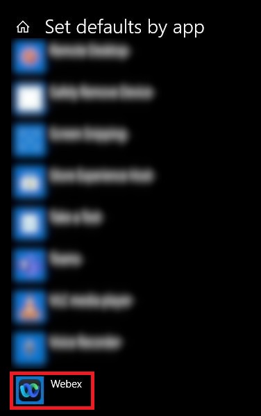
-
For each protocol, choose Webex App.
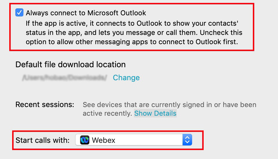
Protocol handlers for macOS
On Mac OS, if other apps registered to the calling protocols before Webex App, users must configure their Webex App to be the default calling option.
In Webex App for Mac, users can confirm that Webex App is selected for the Start calls with setting under general preferences. They can also check Always connect to Microsoft Outlook if they want to make calls in Webex App when they click an Outlook contact's number.
Prepare your environment
General prerequisites
Before you configure a local gateway for Webex Calling, ensure that you:
-
Have a basic knowledge of VoIP principles
-
Have a basic working knowledge of Cisco IOS-XE and IOS-XE voice concepts
-
Have a basic understanding of the Session Initiation Protocol (SIP)
-
Have a basic understanding of Cisco Unified Communications Manager (Unified CM) if your deployment model includes Unified CM
See the Cisco Unified Border Element (CUBE) Enterprise Configuration Guide for details.
Hardware and Software Requirements for Local Gateway
Make sure that your deployment has one or more of the local gateways, such as:
-
Cisco CUBE for IP-based connectivity
-
Cisco IOS Gateway for TDM-based connectivity
The local gateway helps you migrate to Webex Calling at your own pace. The local gateway integrates your existing on-premises deployment with Webex Calling. You can also use your existing PSTN connection. See Get started with Local Gateway
License Requirements for Local Gateways
CUBE calling licenses must be installed on the local gateway. For more information, see the Cisco Unified Border Element Configuration Guide.
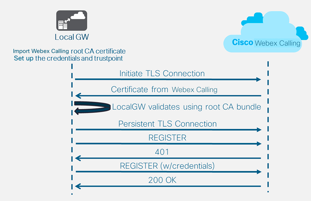
Certificate and Security Requirements for Local Gateway
Webex Calling requires secure signaling and media. The local gateway performs the encryption, and a TLS connection must be established outbound to the cloud with the following steps:
-
The LGW must be updated with the CA root bundle from Cisco PKI
-
A set of SIP digest credentials from Control Hub’s Trunk configuration page are used to configure the LGW (the steps are part of the configuration that follows)
-
CA root bundle validates presented certificate
-
Prompted for credentials (SIP digest provided)
-
The cloud identifies which local gateway is securely registered
Firewall, NAT Traversal, and Media Path Optimization Requirements for Local Gateway
In most cases, the local gateway and endpoints can reside in the internal customer network, using private IP addresses with NAT. The enterprise firewall must allow outbound traffic (SIP, RTP/UDP, HTTP) to specific IP addresses/ports, covered in Port Reference Information.
If you want to utilize Media Path Optimization with ICE, the local gateway’s Webex Calling facing interface must have a direct network path to and from the Webex Calling endpoints. If the endpoints are in a different location and there is no direct network path between the endpoints and the local gateway’s Webex Calling facing interface, then the local gateway must have a public IP address assigned to the interface facing Webex Calling for calls between the local gateway and the endpoints to utilize media path optimization. Additionally, it must be running IOS-XE version 16.12.5.
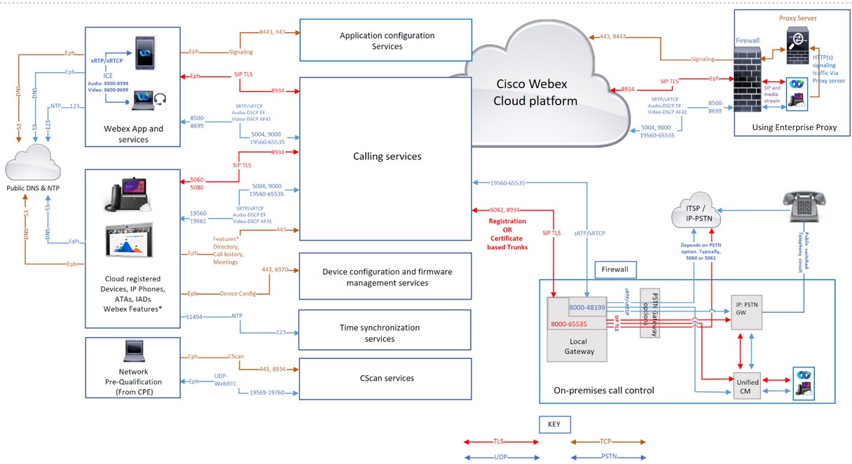
Port Reference Information for Webex Calling
A correctly configured firewall and proxy are essential for a successful Calling deployment. Webex Calling uses SIP and HTTPS for call signaling and the associated addresses and ports for media, network connection, and gateway connectivity as Webex Calling is a global service.
Not all firewall configurations require ports to be open. However, if you're running inside-to-outside rules, you must open ports for the required protocols to let out services.
Network Address Translation (NAT)
Network Address Translation (NAT) and Port Address Translation (PAT) functionality are applied at the border between two networks to translate address spaces or to prevent the collision of IP address spaces.
Organizations use gateway technologies like firewalls and proxies that provide NAT or PAT services to provide internet access to Webex App applications or Webex devices that are on a private IP address space. These gateways make traffic from internal Apps or Devices to the internet appear to be coming from one or more publicly routable IP addresses.
-
If deploying NAT, it’s not mandatory to open an inbound port on the firewall.
-
Validate the NAT pool size required for App or Devices connectivity when multiple app users and devices access Webex Calling & Webex aware services using NAT or PAT. Ensure that adequate public IP addresses are assigned to the NAT pools to prevent port exhaustion. Port exhaustion contributes to internal users and devices being unable to connect to the Webex Calling and Webex Aware services.
-
Define reasonable binding periods and avoid manipulating SIP on the NAT device.
-
Configure a minimum NAT timeout to ensure proper operation of devices. Example: Cisco phones send a follow-up REGISTER refresh message every 1-2 minutes.
-
If your network implements NAT or SPI, then set a larger timeout (of at least 30 minutes) for the connections. This timeout allows reliable connectivity while reducing the battery consumption of the users' mobile devices.
SIP Application Layer Gateway
If a router or firewall is SIP Aware, implying that the SIP Application Layer Gateway (ALG) or similar is enabled, we recommend you turn off this functionality for accurate operation of the service. Although all Webex Calling traffic is encrypted, certain SIP ALG implementations can cause issues with firewall traversal. Therefore, we recommend switching off the SIP ALG to ensure a high quality service.
Check the relevant manufacturer's documentation for steps to disable SIP ALG on specific devices.
Proxy support for Webex Calling
Organizations deploy an internet firewall or internet proxy and firewall, to inspect, restrict, and control the HTTP traffic that leaves and enters their network. Thus protecting their network from various forms of cyberattacks.
Proxies perform several security functions such as:
-
Allow or block access to specific URLs.
-
User authentication
-
IP address/domain/hostname/URI reputation lookup
-
Traffic decryption and inspection
On configuring the proxy feature, it applies to all the applications that use the HTTP's protocol.
The Webex App and Webex device applications include the following:
-
Webex Services
-
Customer device activation (CDA) procedures using Cisco Cloud provisioning platform such as GDS, EDOS device activation, provisioning & onboarding to Webex cloud.
-
Certificate Authentication
-
Firmware Upgrades
-
Status Reports
-
PRT Uploads
-
XSI Services
If a proxy server address is configured, then only the Signaling traffic (HTTP/HTTPS) is sent to the proxy server. Clients that use SIP to register to the Webex Calling service and the associated media aren’t sent to the proxy. Therefore, allow these clients to go through the firewall directly.
Supported Proxy Options, configuration & Authentication types
The supported proxy types are:
-
Explicit Proxy (inspecting or noninspecting)—Configure the clients either App or Device with explicit proxy to specify the server to use.
-
Transparent Proxy (noninspecting)—The Clients aren’t configured to use a specific proxy server address and don’t require any changes to work with a noninspecting proxy.
-
Transparent Proxy (inspecting)—The Clients aren’t configured to use a specific proxy server address. No HTTP's configuration changes are necessary; however, your clients either App or Devices need a root certificate so that they trust the proxy. The IT team uses the inspecting proxies to enforce policies on the websites to visit and the types of content that aren’t permitted.
Configure the proxy addresses manually for the Cisco devices and the Webex App using:
-
Platform OS
-
Device UI
-
Automatically discovered using Web Proxy mechanisms such as:
-
Web Proxy Auto Discovery (WPAD) - Web Proxy Auto Discovery Protocol
-
Proxy Auto Config (PAC) files - Proxy Auto-Config Files
-
While configuring your preferred product types, choose from the following Proxy configurations & authentication types in the table:
|
Product |
Proxy Configuration |
Authentication Type |
|---|---|---|
|
Webex for Mac |
Manual, WPAD, PAC |
No Auth, Basic, NTLM,† |
|
Webex for Windows |
Manual, WPAD, PAC, GPO |
No Auth, Basic, NTLM, †, Negotiate † |
|
Webex for iOS |
Manual, WPAD, PAC |
No Auth, Basic, Digest, NTLM |
|
Webex for Android |
Manual, PAC |
No Auth, Basic, Digest, NTLM |
|
Webex Web App |
Supported through OS |
No Auth, Basic, Digest, NTLM, Negotiate † |
|
Webex Devices |
WPAD, PAC, or Manual |
No Auth, Basic, Digest |
|
Cisco IP Phones |
Manual, WPAD, PAC |
No Auth, Basic, Digest |
|
Webex Video Mesh Node |
Manual |
No Auth, Basic, Digest, NTLM |
For legends in the table:
-
†Mac NTLM Auth - Machine need not be logged on to the domain, user prompted for a password
-
†Windows NTLM Auth - Supported only if a machine is logged onto the domain
-
Negotiate †- Kerberos with NTLM fallback auth.
-
To connect a Cisco Webex Board, Desk, or Room Series device to a proxy server, see Connect your Board, Desk, or Room Series device to a proxy server.
-
For Cisco IP phones, see Set Up a Proxy Server as an example for configuring the proxy server and settings.
For No Authentication, configure the client with a proxy address that doesn’t support authentication. When using Proxy Authentication, configure with valid credentials. Proxies that inspect web traffic may interfere with web socket connections. If this problem occurs, bypassing the not inspecting traffic to *.Webex.com might solve the problem. If you already see other entries, add a semicolon after the last entry, and then enter the Webex exception.
Proxy settings for Windows OS
Microsoft Windows support two network libraries for HTTP traffic (WinINet and WinHTTP) that allow Proxy configuration.WinINet is a superset of WinHTTP.
-
WinInet is designed for single-user, desktop client applications
-
WinHTTP is designed primarily for multiuser, server-based applications
When selecting between the two, choose WinINet for your proxy configuration settings. For details, see wininet-vs-winhttp.
Refer to Configure a list of allowed domains to access Webex while on your corporate network for details on the following:
-
To ensure that people only sign in to applications using accounts from a predefined list of domains.
-
Use a proxy server to intercept requests and limit the domains that are allowed.
Proxy Inspection and Certificate Pinning
The Webex App and Devices validate the certificates of the servers when they establish the TLS sessions. Certificate checks that such as the certificate issuer and digital signature rely on verifying the chain of certificates up to the root certificate. To perform the validation checks, the Webex App and Devices use a set of trusted root CA certificates installed in the operating system trust store.
If you have deployed a TLS-inspecting Proxy to intercept, decrypt and inspect Webex Calling traffic. Ensure that the certificate the Proxy presents (instead of the Webex service certificate) is signed by a certificate authority, and the root certificate is installed in the trust store of your Webex App or Webex device.
-
For Webex App - Install the CA certificate that is used to sign the certificate by the proxy in the operating system of the device.
-
For Webex Room devices and Cisco multiplatform IP Phones - Open a service request with the TAC team to install the CA certificate.
This table shows the Webex App and Webex Devices that support TLS inspection by Proxy servers
|
Product |
Supports Custom Trusted CAs for TLS inspection |
|---|---|
|
Webex App (Windows, Mac, iOS, Android, Web) |
Yes |
|
Webex Room Devices |
Yes |
|
Cisco IP Multiplatform (MPP) Phones |
Yes |
Firewall configuration
Cisco supports Webex Calling and Webex Aware services in secure Cisco and Amazon Web Services (AWS) data centers. Amazon has reserved its IP subnets for Cisco’s sole use, and secured the services located in these subnets within the AWS virtual private cloud.
Configure your firewall to allow communication from your devices, App's applications, and internet-facing services to perform their functions properly. This configuration allows access to all the supported Webex Calling and Webex Aware cloud services, domain names, IP addresses, Ports, and protocols.
Whitelist or open access to the following so that the Webex Calling and Webex Aware services function correctly.
-
The URLs/Domains mentioned under the section Domains and URLs for Webex Calling Services
-
IP subnets, Ports, and Protocols mentioned under the section IP Subnets for Webex Calling Services
-
If you're using the Webex Suite of cloud collaboration services within their organization, Webex Meetings, Messaging, Webex attendant console and other services then ensure you have the IP subnets, Domains/URLs mentioned in these articles are open Network Requirements for Webex Services and Network requirements for Attendant console
If you’re using only a firewall, then filtering Webex Calling traffic using IP addresses alone isn’t supported as some of the IP address pools are dynamic and may change at any time. Update your rules regularly, failing to update your firewall rules list could impact your users' experience. Cisco doesn’t endorse filtering a subset of IP addresses based on a particular geographic region or cloud service provider. Filtering by region can cause severe degradation to the Calling experience.
Cisco doesn't maintain dynamically changing IP address pools hence it isn’t listed in this article.
If your firewall doesn’t support Domain/URL filtering, then use an Enterprise Proxy server option. This option filters/allows by URL/domain the HTTPs signaling traffic to Webex Calling and Webex Aware services in your Proxy server, before forwarding to your firewall.
You can configure traffic using port and IP subnet filtering for call media. Since the media traffic requires direct access to the internet, choose the URL filtering option for signaling traffic.
For Webex Calling, UDP is Cisco’s preferred transport protocol for media, and it recommends using only SRTP over UDP. TCP and TLS as transport protocols for media aren’t supported for Webex Calling in production environments. The connection-orientated nature of these protocols affects media quality over lossy networks. If you have queries regarding the transport protocol, raise a support ticket.
Domains and URLs for Webex Calling services
A * shown at the beginning of a URL (for example, *.webex.com) indicates that services in the top-level domain and all subdomains are accessible.
|
Domain / URL |
Description |
Webex Apps and devices using these domains / URLs |
|---|---|---|
|
Cisco Webex Services | ||
|
*.broadcloudpbx.com |
Webex authorization microservices for cross-launch from Control Hub to Calling Admin Portal. |
Control Hub |
|
*.broadcloud.com.au |
Webex Calling services in Australia. |
All |
|
*.broadcloud.eu |
Webex Calling services in Europe. |
All |
|
*.broadcloudpbx.net |
Calling client configuration and management services. |
Webex Apps |
|
*.webex.com *.cisco.com |
Core Webex Calling & Webex Aware services
When a phone connects to a network for the first time or after a factory reset with no DHCP options set, it contacts a device activation server for zero touch provisioning. New phones use activate.cisco.com and phones with firmware release earlier than 11.2(1), continue to use webapps.cisco.com for provisioning. Download the device firmware and locale updates from binaries.webex.com. Allow Cisco Multiplatform phones (MPPs) older than 12.0.3 version to access sudirenewal.cisco.com through port 80 to renew Manufacturer Installed Certificate (MIC) and have a Secure Unique Device Identifier (SUDI). For details, see Field notice. |
All |
|
*.ucmgmt.cisco.com |
Webex Calling services |
Control Hub |
|
*.wbx2.com and *.ciscospark.com |
Used for cloud awareness to reach out to Webex Calling & Webex Aware services during and after onboarding. These services are necessary for
|
All |
|
*.webexapis.com |
Webex microservices that manage your Webex App applications and Webex devices.
|
All |
|
*.webexcontent.com |
Webex Messaging services related to general file storage including:
|
Webex Apps Messaging services. File storage using webexcontent.com replaced by clouddrive.com in October 2019 |
|
*.accompany.com |
People insights integration |
Webex Apps |
|
Additional Webex related services (Third-Party Domains) | ||
|
*.appdynamics.com *.eum-appdynamics.com |
Performance tracking, error and crash capture, session metrics. |
Control Hub |
|
*.sipflash.com |
Device management services. Firmware upgrades and secure onboarding purposes. |
Webex Apps |
|
*.walkme.com *.walkmeusercontent.com |
Webex user guidance client. Provides onboarding and usage tours for new users. For more information about WalkMe, click here. |
Webex Apps |
|
*.google.com *.googleapis.com |
Notifications to Webex apps on mobile devices (Example: new message, when call is answered) For IP Subnets, refer to these links Google Firebase Cloud Messaging (FCM) service Apple Push Notification Service (APNS) For APNS, Apple lists the IP subnets for this service. | Webex App |
IP Subnets for Webex Calling services
|
IP subnets for Webex Calling services*† | ||
|---|---|---|
|
23.89.0.0/16 |
85.119.56.0/23 |
128.177.14.0/24 |
|
128.177.36.0/24 |
135.84.168.0/21 |
139.177.64.0/21 |
|
139.177.72.0/23 |
144.196.0.0/16 |
150.253.128.0/17 |
|
163.129.0.0/17 |
170.72.0.0/16 |
170.133.128.0/18 |
|
185.115.196.0/22 |
199.19.196.0/23 |
199.19.199.0/24 |
|
199.59.64.0/21 | ||
|
Device configuration and firmware management(Cisco devices) | ||
|
3.20.185.219 |
3.130.87.169 |
3.134.166.179 |
|
52.26.82.54 |
72.163.10.96/27 |
72.163.15.64/26 |
|
72.163.15.128/26 |
72.163.24.0/23 |
72.163.10.128/25 |
|
173.37.146.128/25 |
173.36.127.0/26 |
173.36.127.128/26 |
|
173.37.26.0/23 |
173.37.149.96/27 |
192.133.220.0/26 |
|
192.133.220.64/26 | ||
|
Webex App configuration | ||
|
62.109.192.0/18 |
64.68.96.0/19 |
150.253.128.0/17 |
|
207.182.160.0/19 | ||
|
Connection purpose | Source addresses | Source ports | Protocol | Destination addresses | Destination ports | Notes | |
|---|---|---|---|---|---|---|---|
| Call signaling to Webex Calling (SIP TLS) | Local Gateway external (NIC) | 8000-65535 | TCP | Refer to IP Subnets for Webex Calling Services. | 5062, 8934 |
These IPs/ports are needed for outbound SIP-TLS call signaling from Local Gateways, Devices, and Webex App Applications (Source) to Webex Calling Cloud (Destination). Port 5062 (required for Certificate-based trunk). And port 8934 (required for Registration-based trunk | |
| Devices | 5060-5080 | 8934 | |||||
| Webex App | Ephemeral (OS dependent) | ||||||
| Call signaling from Webex Calling (SIP TLS) to Local Gateway |
Webex Calling address range. Refer to IP Subnets for Webex Calling Services | 8934 | TCP | IP or IP ranges chosen by customer for their Local Gateway | Port or port range chosen by customer for their Local Gateway |
Applies to certificate-based local gateways. It is required to establish a connection from Webex Calling to a Local Gateway. A Registration-based local gateway works on reusing a connection created from the local gateway. Destination port is customer chosen Configure trunks | |
| Call media to Webex Calling (STUN, SRTP/SRTCP, T38, DTLS) | Local Gateway external NIC | 8000-48199†* | UDP | Refer to IP Subnets for Webex Calling Services. |
5004, 9000 (STUN Ports) Audio: 8500-8599 Video: 8600-8699 19560-65535 (SRTP over UDP) |
| |
| Devices†* | 19560-19661 | ||||||
|
VG400 ATA Devices | 19560-19849 | ||||||
| Webex App†* |
Audio: 8500-8599 Video: 8600-8699 | ||||||
|
WebRTC | Ephemeral (According to the browser policy) | ||||||
| Call media from Webex Calling (SRTP/SRTCP, T38) |
Webex Calling address range. Refer to IP Subnets for Webex Calling Services | 19560-65535 (SRTP over UDP) | UDP | IP or IP range chosen by customer for their Local Gateway | Media port range chosen by customer for their Local Gateway | ||
| Call signaling to PSTN gateway (SIP TLS) | Local Gateway internal NIC | 8000-65535 | TCP | Your ITSP PSTN GW or Unified CM | Depends on PSTN option (for example, typically 5060 or 5061 for Unified CM) | ||
| Call media to PSTN gateway (SRTP/SRTCP) | Local Gateway internal NIC | 8000-48199†* | UDP | Your ITSP PSTN GW or Unified CM | Depends on the PSTN option (for example, typically 5060 or 5061 for Unified CM) | ||
| Device configuration and firmware management (Cisco devices) | Webex Calling devices | Ephemeral | TCP |
Refer to IP Subnets for Webex Calling Services | 443, 6970, 80 |
Required for the following reasons:
| |
| Webex App configuration | Webex App applications | Ephemeral | TCP |
Refer to IP Subnets for Webex Calling Services | 443, 8443 | Used for Id broker Authentication, Webex App configuration services for clients, Browser based web access for self-care AND Administrative interface access. The TCP port 8443 is used by Webex App on Cisco Unified CM setup for downloading configuration. Only customers who use the setup to connect to Webex Calling must open the port. | |
| Device time synchronization (NTP) | Webex Calling devices | 51494 | UDP | Refer to IP Subnets for Webex Calling Services. | 123 | These IP addresses are needed for Time Synchronization for Devices (MPP phones, ATAs, and SPA ATAs) | |
|
Domain Name System (DNS) resolution | Webex Calling devices, Webex App, and Webex Devices | Ephemeral | UDP and TCP | Host-defined | 53 | Used for DNS lookups to discover the IP addresses of Webex Calling services in the cloud. Even though typical DNS lookups are done over UDP, some may require TCP, if the query responses can’t fit it in UDP packets. | |
| Network Time Protocol (NTP) | Webex App and Webex Devices | 123 | UDP | Host-defined | 123 | Time Synchronization | |
| CScan | Web based Network readiness Pre-qualification tool for Webex Calling | Ephemeral | TCP | Refer to IP Subnets for Webex Calling Services. | 8934 and 443 | Web based Network readiness Prequalification tool for Webex Calling. Go to cscan.webex.com for more information. | |
| UDP | 19569-19760 | ||||||
| Additional Webex Calling & Webex Aware Services (Third-Party) | |||||||
| Push notifications APNS and FCM services | Webex Calling Applications | Ephemeral | TCP |
Refer to IP Subnets mentioned under the links | 443, 2197, 5228, 5229, 5230, 5223 | Notifications to Webex Apps on mobile devices (Example: When you receive a new message or when a call is answered) | |
-
†*CUBE media port range is configurable with rtp-port range.
-
†*Media ports for devices and applications that are dynamically assigned in the SRTP port rages. SRTP ports are even numbered ports, and the corresponding SRTCP port is allocated with the consecutive odd numbered port.
-
If a proxy server address is configured for your Apps and Devices, the signaling traffic is sent to the proxy. Media transported SRTP over UDP flows directly to your firewall instead of the proxy server.
-
If you’re using NTP and DNS services within your enterprise network, then open the ports 53 and 123 through your firewall.
Quality of Service (QoS)
Allows you to enable tagging of packets from the local device or client to the Webex Calling cloud platform. QoS enables you to prioritize real-time traffic over other data traffic. Enabling this setting modifies the QoS markings for Apps and devices that use SIP signaling and media.
| Source Addresses | Traffic type | Destination addresses | Source ports | Destination ports | DSCP class and value |
|---|---|---|---|---|---|
| Webex App | Audio |
Refer IP subnets, Domains, and URLs for Webex Calling services | 8500-8599 | 8500-8599, 19560-65535 | Expedited Forwarding (46) |
| Webex App | Video | 8600-8699 | 8600-8699, 19560-65535 | Assured Forwarding 41 (34) | |
| Webex App | Signaling | Ephemeral (OS dependent) | 8934 | CS0 (0) | |
| Webex Devices (MPPs and Room) | Audio & Video | 19560-19661 | 19560-65535 |
Expedited Forwarding (46) & Assured Forwarding 41 (34) | |
| Webex Devices | Signaling | 5060-5080 | 8934 | Class Selector 3 (24) |
-
Create a separate QoS profile for Audio and Video/Share since they have different source port range to mark traffic differently.
-
For Windows Clients: To enable UDP Source Port Differentiation for your organization, contact your local account team. Without enabling, you cannot differentiate between the Audio and Video/Share using the Windows QoS Policies (GPO) because the source ports are the same for audio/video/share. For details, see Enable media source port ranges for Webex App
-
For Webex Devices, configure the QoS setting changes from the Control Hub device settings. For details, see Configure & modify device settings in Webex-Calling
Webex Meetings/Messaging - Network Requirements
For customers who’re using Webex Suite of cloud collaboration services, Webex cloud registered products, onboard the MPP devices to the Webex Cloud for services like Call History, Directory Search, Meetings, and Messaging. Ensure that the Domains/URLs/IP Addresses/Ports mentioned in this article are open Network Requirements for Webex Services.
Network Requirements for Webex for Government
For customers who require the list of Domains, URLs, IP address ranges and ports for Webex for Government services, information can be found here: Network requirements for Webex for Government
Network Requirements for Webex Attendant Console
For customers who are using attendant console - receptionists, attendants, and operators feature, ensure Domains/URLs/IP Addresses/Ports/Protocols are open Network requirements for attendant console
Getting started with Webex Calling Local Gateway
For customers using the Local Gateway solution with Webex Calling for premises-based PSTN and third-party SBCs interoperability, read through the article Get Started with Local Gateway
References
To know What's new in Webex Calling, see What's new in Webex Calling
For Security requirements for Webex Calling, see Article
Webex Calling Media Optimization with Interactive Connectivity Establishment (ICE) Article
Document revision history
|
Date |
We've made the following changes to this article |
|---|---|
|
January 21, 2025 |
Added details for using the SIP Application Layer Gateway. |
|
January 8, 2025 |
Moved the IP subnet address related to Device configuration and Webex App configuration to the IP Subnets for Webex Calling services section |
|
December 17, 2024 |
Added support to WebRTC for the Webex Calling Media specification. |
|
November 14, 2024 |
Updated the supported port range for Webex Calling call media for VG400 series ATA device |
|
November 11, 2024 |
Added the supported port range for Webex Calling call media for VG400 series ATA device |
|
July 25, 2024 |
Added back the 52.26.82.54 IP subnet as it’s required for the Cisco ATA device configuration and firmware management. |
|
July 18, 2024 |
Updated with the following details:
|
|
June 28, 2024 |
Updated the usage of both SRTP/ SRTCP port ranges for the Webex Calling Media specification. |
|
June 11, 2024 |
Removed the "huron-dev.com" domain as it’s not used. |
|
May 06, 2024 |
Updated the usage of both SRTP/ SRTCP port ranges for the Webex Calling Media specification. |
|
April 03, 2024 | Updated the IP Subnets for Webex Calling services with 163.129.0.0/17 to accommodate Webex Calling market expansion for the India region. |
|
December 18, 2023 |
Included the sudirenewal.cisco.com URL and port 80 requirement for device configuration and firmware management of the Cisco MPP phone's MIC renewal. |
|
December 11, 2023 |
Updated the IP Subnets for Webex Calling services to include a larger set of IP addresses. 150.253.209.128/25 – changed to 150.253.128.0/17 |
|
November 29, 2023 |
Updated the IP Subnets for Webex Calling services to include a larger set of IP addresses to accommodate Webex Calling region expansion for future growth. 144.196.33.0/25 – changed to 144.196.0.0/16 The IP Subnets for Webex Calling services sections under Webex Calling (SIP TLS) and Call media to Webex Calling (STUN, SRTP) is updated for clarity on certificate-based trunking and the firewall requirements for Local Gateway. |
|
August 14, 2023 |
We’ve added the following IP addresses 144.196.33.0/25 and 150.253.156.128/25 to support increased capacity requirements for Edge and Webex Calling Services. This IP range is supported only in the U.S. region. |
|
July 5, 2023 |
Added the link https://binaries.webex.com to install the Cisco MPP Firmware. |
|
March 7, 2023 |
We've overhauled the entire article to include:
|
|
March 5, 2023 |
Updating the article to include the following:
|
|
November 15, 2022 |
We’ve added the following IP addresses for device configuration and firmware management (Cisco devices):
We’ve removed the following IP addresses from device configuration and firmware management (Cisco devices):
|
|
November 14, 2022 |
Added the IP subnet 170.72.242.0/24 for the Webex Calling service. |
|
September 08, 2022 |
The Cisco MPP Firmware transitions to use https://binaries.webex.com as the host URL for MPP firmware upgrades in all regions. This change improves firmware upgrade performance. |
|
August 30, 2022 |
Removed reference to Port 80 from Device configuration and firmware management (Cisco devices), Application configuration and CScan rows in the Port table as there’s no dependency. |
|
August 18, 2022 |
No change in the solution. Updated the destination ports 5062 (required for Certificate-based trunk), 8934 (required for Registration-based trunk) for Call signaling to Webex Calling (SIP TLS). |
|
July 26, 2022 |
Added the 54.68.1.225 IP Address, which is required for firmware upgrade of Cisco 840/860 devices. |
|
July 21, 2022 |
Updated the destination ports 5062, 8934 for Call signaling to Webex Calling (SIP TLS). |
|
July 14, 2022 |
Added the URLs that support a complete function of Webex Aware services. Added the IP subnet 23.89.154.0/25 for the Webex Calling service. |
|
June 27, 2022 |
Updated the Domain and URLs for Webex Calling services: *.broadcloudpbx.com *.broadcloud.com.au *.broadcloud.eu *.broadcloudpbx.net |
|
June 15, 2022 |
Added the following ports and protocols under IP Addresses and Ports for Webex Calling Services:
Updated information in the Webex Meetings/Messaging - Network Requirements section |
|
May 24, 2022 |
Added the IP subnet 52.26.82.54/24 to 52.26.82.54/32 for Webex Calling service |
|
May 6, 2022 |
Added the IP subnet 52.26.82.54/24 for Webex Calling service |
|
April 7, 2022 |
Updated the Local Gateway internal and external UDP port range to 8000-48198† |
|
April 5, 2022 |
Added the following IP subnets for Webex Calling service:
|
|
March 29, 2022 |
Added the following IP subnets for Webex Calling service:
|
|
September 20, 2021 |
Added 4 new IP subnets for Webex Calling service:
|
|
April 2, 2021 |
Added *.ciscospark.com under Domains and URLs for Webex Calling Services to support Webex Calling use cases in the Webex App. |
|
March 25, 2021 |
Added 6 new IP ranges for activate.cisco.com, which is effective starting May 8, 2021.
|
|
March 4, 2021 |
Replaced Webex Calling discrete IPs and smaller IP ranges with simplified ranges in a separate table for ease of understanding for firewall configuration. |
|
February 26, 2021 |
Added 5004 as destination port for Call media to Webex Calling (STUN, SRTP) to support Interactive Connectivity Establishment (ICE) that will be available in Webex Calling in April 2021. |
|
February 22, 2021 |
Domains and URLs are now listed within a separate table. IP Addresses and Ports table are adjusted to group IP addresses for the same services. Adding the Notes column to the IP Addresses and Ports table that aids in understanding the requirements. Moving the following IP addresses to simplified ranges for device configuration and firmware management (Cisco devices):
Adding the following IP addresses for Application Configuration because Cisco Webex client points to a newer DNS SRV in Australia in March 2021.
|
|
January 21, 2021 |
We’ve added the following IP addresses to device configuration and firmware management (Cisco devices):
We’ve removed the following IP addresses from device configuration and firmware management (Cisco devices):
We’ve added the following IP addresses to the application configuration:
We’ve removed the following IP addresses from the application configuration:
We’ve removed the following port numbers from the application configuration:
We’ve added the following domains to the application configuration:
|
|
December 23, 2020 |
Added new Application Configuration IP addresses to the port reference images. |
|
December 22, 2020 |
Updated the Application Configuration row in the tables to include the following IP addresses: 135.84.171.154 and 135.84.172.154. Hid the network diagrams until these IP addresses are added. |
|
December 11, 2020 |
Updated the Device configuration and firmware management (Cisco devices) and the Application configuration rows for the supported Canadian domains. |
|
October 16, 2020 |
Updated the call signaling and media entries with the following IP addresses:
|
|
September 23, 2020 |
Under CScan, replaced 199.59.64.156 with 199.59.64.197. |
|
August 14, 2020 |
Added more IP addresses to support the introduction of data centers in Canada: Call signaling to Webex Calling (SIP TLS)—135.84.173.0/25,135.84.174.0/25, 199.19.197.0/24, 199.19.199.0/24 |
|
August 12, 2020 |
Added more IP addresses to support the introduction of data centers in Canada:
|
|
July 22, 2020 |
Added the following IP address to support the introduction of data centers in Canada: 135.84.173.146 |
|
June 9, 2020 |
We made the following changes to the CScan entry:
|
|
March 11, 2020 |
We added the following domain and IP addresses to the application configuration:
We updated the following domains with additional IP addresses to device configuration and firmware management:
|
|
February 27, 2020 |
We added the following domain and ports to device configuration and firmware management: cloudupgrader.webex.com—443, 6970 |
Configure Local Gateway on Cisco IOS XE for Webex Calling
Overview
Webex Calling currently supports two versions of Local Gateway:
-
Local Gateway
-
Local Gateway for Webex for Government
-
Before you begin, understand the premises-based Public Switched Telephone Network (PSTN) and Local Gateway (LGW) requirements for Webex Calling. See Cisco Preferred Architecture for Webex Calling for more information.
-
This article assumes that a dedicated Local Gateway platform is in place with no existing voice configuration. If you modify an existing PSTN gateway or CUBE Enterprise deployment to use as the Local Gateway function for Webex Calling, then pay careful attention to the configuration. Ensure that you don't interrupt the existing call flows and functionality because of the changes that you make.
The procedures contain links to command reference documentation where you can learn more about the individual command options. All command reference links go to the Webex Managed Gateways Command Reference unless stated otherwise (in which case, the command links go to Cisco IOS Voice Command Reference). You can access all these guides at Cisco Unified Border Element Command References.
For information on the supported third-party SBCs, refer to the respective product reference documentation.
There are two options to configure the Local Gateway for your Webex Calling trunk:
-
Registration-based trunk
-
Certificate-based trunk
Use the task flow either under the Registration-based Local Gateway or Certificate-based Local Gateway to configure Local Gateway for your Webex Calling trunk.
See Get started with Local Gateway for more information on different trunk types. Perform the following steps on the Local Gateway itself, using the Command Line Interface (CLI). We use Session Initiation Protocol (SIP) and Transport Layer Security (TLS) transport to secure the trunk and Secure Real Time Protocol (SRTP) to secure the media between the Local Gateway and Webex Calling.
-
Select CUBE as your Local Gateway. Webex for Government doesn’t currently support any third-party Session Border Controllers (SBCs). To review the latest list, see Get started with Local Gateway.
- Install Cisco IOS XE Dublin 17.12.1a or later versions for all Webex for Government Local Gateways.
-
To review the list of root Certificate Authorities (CAs) that Webex for Government support, see Root certificate authorities for Webex for Government.
-
For details on the external port ranges for Local Gateway in Webex for Government, see Network requirements for Webex for Government (FedRAMP).
Local Gateway for Webex for Government doesn’t support the following:
-
STUN/ICE-Lite for media path optimization
-
Fax (T.38)
To configure Local Gateway for your Webex Calling trunk in Webex for Government, use the following option:
-
Certificate-based trunk
Use the task flow under the Certificate-based Local Gateway to configure the Local Gateway for your Webex Calling trunk. For more details on how to configure a certificate-based Local Gateway, see Configure Webex Calling certificate-based trunk.
It’s mandatory to configure FIPS-compliant GCM ciphers to support Local Gateway for Webex for Government. If not, the call setup fails. For configuration details, see Configure Webex Calling certificate-based trunk.
Webex for Government doesn’t support registration-based Local Gateway.
This section describes how to configure a Cisco Unified Border Element (CUBE) as a Local Gateway for Webex Calling, using a registering SIP trunk. The first part of this document illustrates how to configure a simple PSTN gateway. In this case, all calls from the PSTN are routed to Webex Calling and all calls from Webex Calling are routed to the PSTN. The image below highlights this solution and the high-level call routing configuration that will be followed.
In this design, the following principal configurations are used:
-
voice class tenants: Used to create trunk specific configurations.
-
voice class uri: Used to classify SIP messages for the selection of an inbound dial-peer.
-
inbound dial-peer: Provides treatment for inbound SIP messages and determines the outbound route using a dial-peer group.
-
dial-peer group: Defines the outbound dial-peers used for onward call routing.
-
outbound dial-peer: Provides treatment for outbound SIP messages and routes them to the required target.
While IP and SIP have become the default protocols for PSTN trunks, TDM (Time Division Multiplexing) ISDN circuits are still widely used and are supported with Webex Calling trunks. To enable media optimization of IP paths for Local Gateways with TDM-IP call flows, it is currently necessary to use a two-leg call routing process. This approach modifies the call routing configuration shown above, by introducing a set of internal loop-back dial-peers between Webex Calling and PSTN trunks as illustrated in the image below.
When connecting an on-premises Cisco Unified Communications Manager solution with Webex Calling, you can use the simple PSTN gateway configuration as a baseline for building the solution illustrated in the following diagram. In this case, Unified Communications Manager provides centralized routing and treatment of all PSTN and Webex Calling calls.
Throughout this document, the host names, IP addresses, and interfaces illustrated in the following image are used.
Use the configuration guidance in the rest of this document to complete your Local Gateway configuration as follows:
-
Step 1: Configure router baseline connectivity and security
-
Step 2: Configure Webex Calling Trunk
Depending on your required architecture, follow either:
-
Step 3: Configure Local Gateway with SIP PSTN trunk
-
Step 4: Configure Local Gateway with an existing Unified CM environment
Or:
-
Step 3: Configure Local Gateway with TDM PSTN trunk
Baseline configuration
The first step in preparing your Cisco router as a Local Gateway for Webex Calling is to build a baseline configuration that secures your platform and establishes connectivity.
-
All registration-based Local Gateway deployments require Cisco IOS XE 17.6.1a or later versions. Cisco IOS 17.12.2 or later is recommended. For the recommended versions, see the Cisco Software Research page. Search for the platform and select one of the suggested releases.
-
ISR4000 series routers must be configured with both Unified Communications and Security technology licenses.
-
Catalyst Edge 8000 series routers fitted with voice cards or DSPs require DNA Advantage licensing. Routers without voice cards or DSPs require a minimum of DNA Essentials licensing.
-
-
Build a baseline configuration for your platform that follows your business policies. In particular, configure and verify the following:
-
NTP
-
ACLs
-
User authentication and remote access
-
DNS
-
IP routing
-
IP addresses
-
-
The network toward Webex Calling must use an IPv4 address.
-
Upload the Cisco root CA bundle to the Local Gateway.
Configuration
| 1 |
Ensure that you assign valid and routable IP addresses to any Layer 3 interfaces, for example:
|
| 2 |
Protect registration and STUN credentials on the router using symmetric encryption. Configure the primary encryption key and encryption type as follows:
|
| 3 |
Create a placeholder PKI trustpoint. Requires this trustpoint to configure TLS later. For registration-based trunks, this trustpoint doesn't require a certificate - as would be required for a certificate-based trunk. |
| 4 |
Enable TLS1.2 exclusivity and specify the default trustpoint using the following configuration commands. Transport parameters should also be updated to ensure a reliable secure connection for registration: The cn-san-validate server command ensures that the Local Gateway permits a connection if the host name configured in tenant 200 is included in either the CN or SAN fields of the certificate received from the outbound proxy.
|
| 5 |
Install the Cisco root CA bundle, which includes the DigiCert CA certificate used by Webex Calling. Use the crypto pki trustpool import clean url command to download the root CA bundle from the specified URL, and to clear the current CA trustpool, then install the new bundle of certificates: If you need to use a proxy for access to the internet using HTTPS, add the following configuration before importing the CA bundle: ip http client proxy-server yourproxy.com proxy-port 80 |
| 1 |
Create a registration based PSTN trunk for an existing location in the Control Hub. Make a note of the trunk information that is provided once the trunk has been created. The details highlighted in the illustration are used in the configuration steps in this guide. For more information, see Configure trunks, route groups, and dial plans for Webex Calling. |
| 2 |
Enter the following commands to configure CUBE as a Webex Calling Local Gateway: Here's an explanation of the fields for the configuration:
Enables Cisco Unified Border Element (CUBE) features on the platform. media statisticsEnables media monitoring on the Local Gateway. media bulk-statsEnables the control plane to poll the data plane for bulk call statistics. For more information on these commands, see Media. allow-connections sip to sipEnable CUBE basic SIP back-to-back user agent functionality. For more information, see Allow connections. By default, T.38 fax transport is enabled. For more information, see fax protocol t38 (voice-service). Enables STUN (Session Traversal of UDP through NAT) globally.
For more information, see stun flowdata agent-id and stun flowdata shared-secret. asymmetric payload fullConfigures SIP asymmetric payload support for both DTMF and dynamic codec payloads. For more information, see asymmetric payload. early-offer forcedForces the Local Gateway to send SDP information in the initial INVITE message instead of waiting for acknowledgment from the neighboring peer. For more information on this command, see early-offer. |
| 3 |
Configure voice class codec 100 allowing G.711 codecs only for all trunks. This simple approach is suitable for most deployments. If required, additional codec types supported by both originating and terminating systems may be added to the list. More complex solutions involving transcoding using DSP modules are supported, but not included in this guide. Here's an explanation of the fields for the configuration: voice class codec 100Used to only allow preferred codecs for SIP trunk calls. For more information, see voice class codec. |
| 4 |
Configure voice class stun-usage 100 to enable ICE on the Webex Calling trunk. Here's an explanation of the fields for the configuration: stun usage ice liteUsed to enable ICE-Lite for all Webex Calling facing dial-peers to allow media-optimization whenever possible. For more information, see voice class stun usage and stun usage ice lite. Media optimization is negotiated wherever possible. If a call requires cloud media services, such as recording, the media cannot be optimized. |
| 5 |
Configure the media encryption policy for Webex traffic. Here's an explanation of the fields for the configuration: voice class srtp-crypto 100Specifies SHA1_80 as the only SRTP cipher-suite CUBE offers in the SDP in offer and answer messages. Webex Calling only supports SHA1_80. For more information, see voice class srtp-crypto. |
| 6 |
Configure a pattern to identify calls to a Local Gateway trunk based on its destination trunk parameter: Here's an explanation of the fields for the configuration: voice class uri 100 sipDefines a pattern to match an incoming SIP invite to an incoming trunk dial-peer. When entering this pattern, use dtg= followed by the Trunk OTG/DTG value provided in the Control Hub when the trunk was created. For more information, see voice class uri. |
| 7 |
Configure sip profile 100, which will be used to modify SIP messages before they are sent to Webex Calling.
Here's an explanation of the fields for the configuration:
United States or Canadian PSTN provider can offer the Caller ID verification for Spam and fraud calls, with the additional configuration mentioned in the Spam or fraud call indication in Webex Calling article. |
| 8 |
Configure Webex Calling trunk: |
After you define the tenant 100 and configure a SIP VoIP dial-peer, the gateway initiates a TLS connection toward Webex Calling. At this point, the access SBC presents its certificate to the Local Gateway. The Local Gateway validates the Webex Calling access SBC certificate using the CA root bundle that was updated earlier. If the certificate is recognized, a persistent TLS session is established between the Local Gateway and Webex Calling access SBC. The Local Gateway is then able to use this secure connection to register with the Webex access SBC. When the registration is challenged for authentication:
-
The username, password, and realm parameters from the credentials configuration is used in the response.
-
The modification rules in sip profile 100 are used to convert SIPS URL back to SIP.
Registration is successful when a 200 OK is received from the access SBC.
Having built a trunk towards Webex Calling above, use the following configuration to create a non-encrypted trunk towards a SIP based PSTN provider:
If your Service Provider offers a secure PSTN trunk, you may follow a similar configuration as detailed above for the Webex Calling trunk. CUBE supports secure call routing.
If you are using a TDM / ISDN PSTN trunk, skip to the next section Configure Local Gateway with TDM PSTN trunk.
To configure TDM interfaces for PSTN call legs on the Cisco TDM-SIP Gateways, see Configuring ISDN PRI.
| 1 |
Configure the following voice class uri to identify inbound calls from the PSTN trunk: Here's an explanation of the fields for the configuration: voice class uri 200 sipDefines a pattern to match an incoming SIP invite to an incoming trunk dial-peer. When entering this pattern, use the IP address of your IP PSTN gateway. For more information, see voice class uri. |
| 2 |
Configure the following IP PSTN dial-peer: Here's an explanation of the fields for the configuration: Defines a VoIP dial-peer with a tag of 200 and gives a meaningful description for ease of management and troubleshooting. For more information, see dial-peer voice. destination-pattern BAD.BADA dummy destination pattern is required when routing outbound calls using an inbound dial-peer group. Any valid destination pattern may be used in this case. For more information, see destination-pattern (interface). session protocol sipv2Specifies that this dial-peer handles SIP call legs. For more information, see session protocol (dial peer). session target ipv4: 192.168.80.13Specifies the target address for calls sent to the PSTN provider. This could be either an IP address or DNS host name. For more information, see session target (VoIP dial peer). incoming uri via 200Specifies the voice class used to match incoming calls to this dial-peer using the INVITE VIA header URI. For more information, see incoming url.
voice-class sip asserted-id pai
(Optional) Turns on P-Asserted-Identity header processing and controls how this is used for the PSTN trunk. If this command is used, the calling party identity provided from the incoming dial-peer is used for the outgoing From and P-Asserted-Identity headers. If this command is not used, the calling party identity provided from the incoming dial-peer is used for the outgoing From and Remote-Party-ID headers. For more information, see voice-class sip asserted-id.
bind control
source-interface
GigabitEthernet0/0/0
Configures the source interface and associated IP address for messages sent to the PSTN. For more information, see bind. bind media source-interface GigabitEthernet0/0/0Configures the source interface and associated IP address for media sent to PSTN. For more information, see bind. voice-class codec 100Configures the dial-peer to use the common codec filter list 100. For more information, see voice-class codec. dtmf-relay rtp-nteDefines RTP-NTE (RFC2833) as the DTMF capability expected on the call leg. For more information, see DTMF Relay (Voice over IP). no vadDisables voice activity detection. For more information, see vad (dial peer). |
| 3 |
If you are configuring your Local Gateway to only route calls between Webex Calling and the PSTN, add the following call routing configuration. If you are configuring your Local Gateway with a Unified Communications Manager platform, skip to the next section. |
Having built a trunk towards Webex Calling, use the following configuration to create a TDM trunk for your PSTN service with loop-back call routing to allow media optimization on the Webex call leg.
If you do not require IP media optimization, follow the configuration steps for a SIP PSTN trunk. Use a voice port and POTS dial-peer (as shown in Steps 2 and 3) instead of the PSTN VoIP dial-peer.
| 1 |
The loop-back dial-peer configuration uses dial-peer groups and call routing tags to ensure that calls pass correctly between Webex and the PSTN, without creating call routing loops. Configure the following translation rules that will be used to add and remove the call routing tags: Here's an explanation of the fields for the configuration: voice translation-ruleUses regular expressions defined in rules to add or remove call routing tags. Over-decadic digits (‘A’) are used to add clarity for troubleshooting. In this configuration, the tag added by translation-profile 100 is used to guide calls from Webex Calling towards the PSTN via the loopback dial-peers. Similarly, the tag added by translation-profile 200 is used to guide calls from the PSTN towards Webex Calling. Translation-profiles 11 and 12 remove these tags before delivering calls to the Webex and PSTN trunks respectively. This example assumes that called numbers from Webex Calling are presented in +E.164 format. Rule 100 removes the leading + to maintain a valid called number. Rule 12 then adds a national or international routing digit(s) when removing the tag. Use digits that suit your local ISDN national dial plan. If Webex Calling presents numbers in national format, adjust rules 100 and 12 to simply add and remove the routing tag respectively. For more information, see voice translation-profile and voice translation-rule. |
| 2 |
Configure TDM voice interface ports as required by the trunk type and protocol used. For more information, see Configuring ISDN PRI. For example, the basic configuration of a Primary Rate ISDN interface installed in NIM slot 2 of a device might include the following: |
| 3 |
Configure the following TDM PSTN dial-peer: Here's an explanation of the fields for the configuration: Defines a VoIP dial-peer with a tag of 200 and gives a meaningful description for ease of management and troubleshooting. For more information, see dial-peer voice. destination-pattern BAD.BADA dummy destination pattern is required when routing outbound calls using an inbound dial-peer group. Any valid destination pattern may be used in this case. For more information, see destination-pattern (interface). translation-profile incoming 200Assigns the translation profile that will add a call routing tag to the incoming called number. direct-inward-dialRoutes the call without providing a secondary dial-tone. For more information, see direct-inward-dial. port 0/2/0:15The physical voice port associated with this dial-peer. |
| 4 |
To enable media optimization of IP paths for Local Gateways with TDM-IP call flows, you can modify the call routing by introducing a set of internal loop-back dial-peers between Webex Calling and PSTN trunks. Configure the following loop-back dial-peers. In this case, all incoming calls will be routed initially to dial-peer 10 and from there to either dial-peer 11 or 12 based on the applied routing tag. After removal of the routing tag, calls will be routed to the outbound trunk using dial-peer groups. Here's an explanation of the fields for the configuration: Defines a VoIP dial-peer and gives a meaningful description for ease of management and troubleshooting. For more information, see dial-peer voice. translation-profile incoming 11Applies the translation profile defined earlier to remove the call routing tag before passing to the outbound trunk. destination-pattern BAD.BADA dummy destination pattern is required when routing outbound calls using an inbound dial-peer group. For more information, see destination-pattern (interface). session protocol sipv2Specifies that this dial-peer handles SIP call legs. For more information, see session protocol (dial peer). session target ipv4: 192.168.80.14Specifies the local router interface address as the call target to loop-back. For more information, see session target (voip dial peer). bind control source-interface GigabitEthernet0/0/0Configures the source interface and associated IP address for messages sent through the loop-back. For more information, see bind. bind media source-interface GigabitEthernet0/0/0Configures the source interface and associated IP address for media sent through the loop-back. For more information, see bind. dtmf-relay rtp-nteDefines RTP-NTE (RFC2833) as the DTMF capability expected on the call leg. For more information, see DTMF Relay (Voice over IP). codec g711alaw Forces all PSTN calls to use G.711. Select a-law or u-law to match the companding method used by your ISDN service. no vadDisables voice activity detection. For more information, see vad (dial peer). |
| 5 |
Add the following call routing configuration: This concludes your Local Gateway configuration. Save the configuration and reload the
platform if this is the first time CUBE features are configured.
|
The PSTN-Webex Calling configuration in the previous sections may be modified to include additional trunks to a Cisco Unified Communications Manager (UCM) cluster. In this case, all calls are routed via Unified CM. Calls from UCM on port 5060 are routed to the PSTN and calls from port 5065 are routed to Webex Calling. The following incremental configurations may be added to include this calling scenario.
When creating the Webex Calling trunk in Unified CM, ensure that you configure the incoming port in the SIP Trunk Security Profile settings to 5065. This allows incoming messages on port 5065 and populate the VIA header with this value when sending messages to the Local Gateway.
| 1 |
Configure the following voice class URIs: |
| 2 |
Configure the following DNS records to specify SRV routing to Unified CM hosts: IOS XE uses these records for locally determining target UCM hosts and ports. With this configuration, it is not required to configure records in your DNS system. If you prefer to use your DNS, then these local configurations are not required. Here's an explanation of the fields for the configuration: The following command creates a DNS SRV resource record. Create a record for each UCM host and trunk: ip host _sip._udp.pstntocucm.io srv 2 1 5060 ucmsub5.mydomain.com _sip._udp.pstntocucm.io: SRV resource record name 2: The SRV resource record priority 1: The SRV resource record weight 5060: The port number to use for the target host in this resource record ucmsub5.mydomain.com: The resource record target host To resolve the resource record target host names, create local DNS A records. For example: ip host ucmsub5.mydomain.com 192.168.80.65 ip host: Creates a record in the local IOS XE database. ucmsub5.mydomain.com: The A record host name. 192.168.80.65: The host IP address. Create the SRV resource records and A records to reflect your UCM environment and preferred call distribution strategy. |
| 3 |
Configure the following dial-peers: |
| 4 |
Add call routing using the following configurations: |
Diagnostic Signatures (DS) proactively detects commonly observed issues in the IOS XE-based Local Gateway and generates email, syslog, or terminal message notification of the event. You can also install the DS to automate diagnostics data collection and transfer-collected data to the Cisco TAC case to accelerate resolution time.
Diagnostic Signatures (DS) are XML files that contain information about problem trigger events and actions to be taken to inform, troubleshoot, and remediate the issue. You can define the problem detection logic using syslog messages, SNMP events and through periodic monitoring of specific show command outputs.
The action types include collecting show command outputs:
-
Generating a consolidated log file
-
Uploading the file to a user-provided network location such as HTTPS, SCP, FTP server.
TAC engineers author the DS files and digitally sign it for integrity protection. Each DS file has a unique numerical ID assigned by the system. Diagnostic Signatures Lookup Tool (DSLT) is a single source to find applicable signatures for monitoring and troubleshooting various problems.
Before you begin:
-
Do not edit the DS file that you download from DSLT. The files that you modify fail installation due to the integrity check error.
-
A Simple Mail Transfer Protocol (SMTP) server you require for the Local Gateway to send out email notifications.
-
Ensure that the Local Gateway is running IOS XE 17.6.1 or higher if you wish to use the secure SMTP server for email notifications.
Prerequisites
Local Gateway running IOS XE 17.6.1a or higher
-
Diagnostic Signatures is enabled by default.
-
Configure the secure email server to be used to send proactive notification if the device is running Cisco IOS XE 17.6.1a or higher.
configure terminal call-home mail-server <username>:<pwd>@<email server> priority 1 secure tls end -
Configure the environment variable ds_email with the email address of the administrator to notify you.
configure terminal
call-home
diagnostic-signature
environment ds_email <email address>
end
The following shows an example configuration of a Local Gateway running on Cisco IOS XE 17.6.1a or higher to send the proactive notifications to tacfaststart@gmail.com using Gmail as the secure SMTP server:
We recommend you to use the Cisco IOS XE Bengaluru 17.6.x or later versions.
call-home
mail-server tacfaststart:password@smtp.gmail.com priority 1 secure tls
diagnostic-signature
environment ds_email "tacfaststart@gmail.com"
A Local Gateway running on Cisco IOS XE Software is not a typical web-based Gmail client that supports OAuth, so we must configure a specific Gmail account setting and provide specific permission to have the email from the device processed correctly:
-
Go to and turn on the Less secure app access setting.
-
Answer “Yes, it was me” when you receive an email from Gmail stating “Google prevented someone from signing into your account using a non-Google app.”
Install diagnostic signatures for proactive monitoring
Monitoring high CPU utilization
This DS tracks CPU utilization for five seconds using the SNMP OID 1.3.6.1.4.1.9.2.1.56. When the utilization reaches 75% or more, it disables all debugs and uninstalls all diagnostic signatures that are installed in the Local Gateway. Use these steps below to install the signature.
-
Use the show snmp command to enable SNMP. If you do not enable, then configure the snmp-server manager command.
show snmp %SNMP agent not enabled config t snmp-server manager end show snmp Chassis: ABCDEFGHIGK 149655 SNMP packets input 0 Bad SNMP version errors 1 Unknown community name 0 Illegal operation for community name supplied 0 Encoding errors 37763 Number of requested variables 2 Number of altered variables 34560 Get-request PDUs 138 Get-next PDUs 2 Set-request PDUs 0 Input queue packet drops (Maximum queue size 1000) 158277 SNMP packets output 0 Too big errors (Maximum packet size 1500) 20 No such name errors 0 Bad values errors 0 General errors 7998 Response PDUs 10280 Trap PDUs Packets currently in SNMP process input queue: 0 SNMP global trap: enabled -
Download DS 64224 using the following drop-down options in Diagnostic Signatures Lookup Tool:
Field Name
Field Value
Platform
Cisco 4300, 4400 ISR Series or Cisco CSR 1000V Series
Product
CUBE Enterprise in Webex Calling Solution
Problem Scope
Performance
Problem Type
High CPU Utilization with Email Notification.
-
Copy the DS XML file to the Local Gateway flash.
LocalGateway# copy ftp://username:password@<server name or ip>/DS_64224.xml bootflash:The following example shows copying the file from an FTP server to the Local Gateway.
copy ftp://user:pwd@192.0.2.12/DS_64224.xml bootflash: Accessing ftp://*:*@ 192.0.2.12/DS_64224.xml...! [OK - 3571/4096 bytes] 3571 bytes copied in 0.064 secs (55797 bytes/sec) -
Install the DS XML file in the Local Gateway.
call-home diagnostic-signature load DS_64224.xml Load file DS_64224.xml success -
Use the show call-home diagnostic-signature command to verify that the signature is successfully installed. The status column should have a “registered” value.
show call-home diagnostic-signature
Current diagnostic-signature settings:
Diagnostic-signature: enabled
Profile: CiscoTAC-1 (status: ACTIVE)
Downloading  URL(s):  https://tools.cisco.com/its/service/oddce/services/DDCEService
Environment variable:
ds_email: username@gmail.com
Download DSes:
DS ID
DS Name
Revision
Status
Last Update (GMT+00:00)
64224
DS_LGW_CPU_MON75
0.0.10
Registered
2020-11-07 22:05:33
When triggered, this signature uninstalls all running DSs including itself. If necessary, reinstall DS 64224 to continue monitoring high CPU utilization on the Local Gateway.
Monitoring SIP trunk registration
This DS checks for unregistration of a Local Gateway SIP Trunk with Webex Calling cloud every 60 seconds. Once the unregistration event is detected, it generates an email and syslog notification and uninstalls itself after two unregistration occurrences. Use the steps below to install the signature:
-
Download DS 64117 using the following drop-down options in Diagnostic Signatures Lookup Tool:
Field Name
Field Value
Platform
Cisco 4300, 4400 ISR Series or Cisco CSR 1000V Series
Product
CUBE Enterprise in Webex Calling Solution
Problem Scope
SIP-SIP
Problem Type
SIP Trunk Unregistration with Email Notification.
-
Copy the DS XML file to the Local Gateway.
copy ftp://username:password@<server name or ip>/DS_64117.xml bootflash: -
Install the DS XML file in the Local Gateway.
call-home diagnostic-signature load DS_64117.xml Load file DS_64117.xml success LocalGateway# -
Use the show call-home diagnostic-signature command to verify that the signature is successfully installed. The status column must have a “registered” value.
Monitoring abnormal call disconnects
This DS uses SNMP polling every 10 minutes to detect abnormal call disconnect with SIP errors 403, 488 and 503. If the error count increment is greater than or equal to 5 from the last poll, it generates a syslog and email notification. Please use the steps below to install the signature.
-
Use the show snmp command to check whether SNMP is enabled. If it is not enabled, configure the snmp-server manager command.
show snmp %SNMP agent not enabled config t snmp-server manager end show snmp Chassis: ABCDEFGHIGK 149655 SNMP packets input 0 Bad SNMP version errors 1 Unknown community name 0 Illegal operation for community name supplied 0 Encoding errors 37763 Number of requested variables 2 Number of altered variables 34560 Get-request PDUs 138 Get-next PDUs 2 Set-request PDUs 0 Input queue packet drops (Maximum queue size 1000) 158277 SNMP packets output 0 Too big errors (Maximum packet size 1500) 20 No such name errors 0 Bad values errors 0 General errors 7998 Response PDUs 10280 Trap PDUs Packets currently in SNMP process input queue: 0 SNMP global trap: enabled -
Download DS 65221 using the following options in Diagnostic Signatures Lookup Tool:
Field Name
Field Value
Platform
Cisco 4300, 4400 ISR Series or Cisco CSR 1000V Series
Product
CUBE Enterprise in Webex Calling Solution
Problem Scope
Performance
Problem Type
SIP abnormal call disconnect detection with Email and Syslog Notification.
-
Copy the DS XML file to the Local Gateway.
copy ftp://username:password@<server name or ip>/DS_65221.xml bootflash: -
Install the DS XML file in the Local Gateway.
call-home diagnostic-signature load DS_65221.xml Load file DS_65221.xml success -
Use the show call-home diagnostic-signature command to verify that the signature is successfully installed. The status column must have a “registered” value.
Install diagnostic signatures to troubleshoot a problem
Use Diagnostic Signatures (DS) to resolve issues quickly. Cisco TAC engineers have authored several signatures that enable the necessary debugs that are required to troubleshoot a given problem, detect the problem occurrence, collect the right set of diagnostic data and transfer the data automatically to the Cisco TAC case. Diagnostic Signatures (DS) eliminate the need to manually check for the problem occurrence and makes troubleshooting of intermittent and transient issues a lot easier.
You can use the Diagnostic Signatures Lookup Tool to find the applicable signatures and install them to self-solve a given issue or you can install the signature that is recommended by the TAC engineer as part of the support engagement.
Here is an example of how to find and install a DS to detect the occurrence “%VOICE_IEC-3-GW: CCAPI: Internal Error (call spike threshold): IEC=1.1.181.1.29.0" syslog and automate diagnostic data collection using the following steps:
-
Configure an additional DS environment variable ds_fsurl_prefix which is the Cisco TAC file server path (cxd.cisco.com) to which the collected diagnostics data are uploaded. The username in the file path is the case number and the password is the file upload token which can be retrieved from Support Case Manager in the following command. The file upload token can be generated in the Attachments section of the Support Case Manager, as needed.
configure terminal
call-home
diagnostic-signature
LocalGateway(cfg-call-home-diag-sign)environment ds_fsurl_prefix "scp://<case number>:<file upload token>@cxd.cisco.com"
end
Example:
call-home diagnostic-signature environment ds_fsurl_prefix " environment ds_fsurl_prefix "scp://612345678:abcdefghijklmnop@cxd.cisco.com" -
Ensure that SNMP is enabled using the show snmp command. If it is not enabled, configure the snmp-server manager command.
show snmp %SNMP agent not enabled config t snmp-server manager end -
Ensure to install the High CPU monitoring DS 64224 as a proactive measure to disable all debugs and diagnostics signatures during the time of high CPU utilization. Download DS 64224 using the following options in Diagnostic Signatures Lookup Tool:
Field Name
Field Value
Platform
Cisco 4300, 4400 ISR Series or Cisco CSR 1000V Series
Product
CUBE Enterprise in Webex Calling Solution
Problem Scope
Performance
Problem Type
High CPU Utilization with Email Notification.
-
Download DS 65095 using the following options in Diagnostic Signatures Lookup Tool:
Field Name
Field Value
Platform
Cisco 4300, 4400 ISR Series or Cisco CSR 1000V Series
Product
CUBE Enterprise in Webex Calling Solution
Problem Scope
Syslogs
Problem Type
Syslog - %VOICE_IEC-3-GW: CCAPI: Internal Error (Call spike threshold): IEC=1.1.181.1.29.0
-
Copy the DS XML files to the Local Gateway.
copy ftp://username:password@<server name or ip>/DS_64224.xml bootflash: copy ftp://username:password@<server name or ip>/DS_65095.xml bootflash: -
Install the High CPU monitoring DS 64224 and then DS 65095 XML file in the Local Gateway.
call-home diagnostic-signature load DS_64224.xml Load file DS_64224.xml success call-home diagnostic-signature load DS_65095.xml Load file DS_65095.xml success -
Verify that the signature is successfully installed using the show call-home diagnostic-signature command. The status column must have a “registered” value.
show call-home diagnostic-signature
Current diagnostic-signature settings:
Diagnostic-signature: enabled
Profile: CiscoTAC-1 (status: ACTIVE)
Downloading  URL(s):  https://tools.cisco.com/its/service/oddce/services/DDCEService
Environment variable:
           ds_email: username@gmail.com
           ds_fsurl_prefix: scp://612345678:abcdefghijklmnop@cxd.cisco.com
Downloaded DSes:
DS ID
DS Name
Revision
Status
Last Update (GMT+00:00)
64224
00:07:45
DS_LGW_CPU_MON75
0.0.10
Registered
2020-11-08
65095
00:12:53
DS_LGW_IEC_Call_spike_threshold
0.0.12
Registered
2020-11-08
Verify diagnostic signatures execution
In the following command, the “Status” column of the show call-home diagnostic-signature command changes to “running” while the Local Gateway executes the action defined within the signature. The output of show call-home diagnostic-signature statistics is the best way to verify whether a diagnostic signature detects an event of interest and executes the action. The “Triggered/Max/Deinstall” column indicates the number of times the given signature has triggered an event, the maximum number of times it is defined to detect an event and whether the signature deinstalls itself after detecting the maximum number of triggered events.
show call-home diagnostic-signature
Current diagnostic-signature settings:
Diagnostic-signature: enabled
Profile: CiscoTAC-1 (status: ACTIVE)
Downloading  URL(s):  https://tools.cisco.com/its/service/oddce/services/DDCEService
Environment variable:
           ds_email: carunach@cisco.com
           ds_fsurl_prefix: scp://612345678:abcdefghijklmnop@cxd.cisco.com
Downloaded DSes:
|
DS ID |
DS Name |
Revision |
Status |
Last Update (GMT+00:00) |
|---|---|---|---|---|
| 64224 |
DS_LGW_CPU_MON75 |
0.0.10 |
Registered |
2020-11-08 00:07:45 |
|
65095 |
DS_LGW_IEC_Call_spike_threshold |
0.0.12 |
Running |
2020-11-08 00:12:53 |
show call-home diagnostic-signature statistics
|
DS ID |
DS Name |
Triggered/Max/Deinstall |
Average Run Time (seconds) |
Max Run Time (seconds) |
|---|---|---|---|---|
| 64224 |
DS_LGW_CPU_MON75 |
0/0/N |
0.000 |
0.000 |
|
65095 |
DS_LGW_IEC_Call_spike_threshold |
1/20/Y |
23.053 |
23.053 |
The notification email that is sent during diagnostic signature execution contains key information such as issue type, device details, software version, running configuration, and show command outputs that are relevant to troubleshoot the given problem.
Uninstall diagnostic signatures
Use Diagnostic signatures for troubleshooting purposes are typically defined to uninstall after detection of some problem occurrences. If you want to uninstall a signature manually, retrieve the DS ID from the output of the show call-home diagnostic-signature command and run the following command:
call-home diagnostic-signature deinstall <DS ID>
Example:
call-home diagnostic-signature deinstall 64224
New signatures are added to Diagnostics Signatures Lookup Tool periodically, based on issues that are commonly observed in deployments. TAC currently doesn’t support requests to create new custom signatures.
For better management of Cisco IOS XE Gateways, we recommend that you enroll and manage the gateways through the Control Hub. It is an optional configuration. When enrolled, you can use the configuration validation option in the Control Hub to validate your Local Gateway configuration and identify any configuration issues. Currently, only registration-based trunks support this functionality.
For more information, refer the following:
This section describes how to configure a Cisco Unified Border Element (CUBE) as a Local Gateway for Webex Calling using a certificate-based, mutual TLS (mTLS) SIP trunk. The first part of this document illustrates how to configure a simple PSTN gateway. In this case, all calls from the PSTN are routed to Webex Calling and all calls from Webex Calling are routed to the PSTN. The following image highlights this solution and the high-level call routing configuration that will be followed.
In this design, the following principal configurations are used:
-
voice class tenants: Used to create trunk specific configurations.
-
voice class uri: Used to classify SIP messages for the selection of an inbound dial-peer.
-
inbound dial-peer: Provides treatment for inbound SIP messages and determines the outbound route using a dial-peer group.
-
dial-peer group: Defines the outbound dial-peers used for onward call routing.
-
outbound dial-peer: Provides treatment for outbound SIP messages and routes them to the required target.
When connecting an on-premises Cisco Unified Communications Manager solution with Webex Calling, you can use the simple PSTN gateway configuration as a baseline for building the solution illustrated in the following diagram. In this case, a Unified Communications Manager provides centralized routing and treatment of all PSTN and Webex Calling calls.
Throughout this document, the host names, IP addresses, and interfaces illustrated in the following image are used. Options are provided for public or private (behind NAT) addressing. SRV DNS records are optional, unless load balancing across multiple CUBE instances.
Use the configuration guidance in the rest of this document to complete your Local Gateway configuration as follows:
Baseline configuration
The first step in preparing your Cisco router as a Local Gateway for Webex Calling is to build a baseline configuration that secures your platform and establishes connectivity.
-
All certificate-based Local Gateway deployments require Cisco IOS XE 17.9.1a or later versions. Cisco IOS XE 17.12.2 or later is recommended. For the recommended versions, see the Cisco Software Research page. Search for the platform and select one of the suggested releases.
-
ISR4000 series routers must be configured with both Unified Communications and Security technology licenses.
-
Catalyst Edge 8000 series routers fitted with voice cards or DSPs require DNA Advantage licensing. Routers without voice cards or DSPs require a minimum of DNA Essentials licensing.
-
For high-capacity requirements, you may also require a High Security (HSEC) license and additional throughput entitlement.
Refer to Authorization Codes for further details.
-
-
Build a baseline configuration for your platform that follows your business policies. In particular, configure and verify the following:
-
NTP
-
ACLs
-
User authentication and remote access
-
DNS
-
IP routing
-
IP addresses
-
-
The network toward Webex Calling must use an IPv4 address. Local Gateway Fully Qualified Domain Names (FQDN) or Service Record (SRV) addresses configured in the Control Hub must resolve to a public IPv4 address on the internet.
-
All SIP and media ports on the Local Gateway interface facing Webex must be accessible from the internet, either directly or via static NAT. Ensure that you update your firewall accordingly.
-
Follow the detailed configuration steps provided below to install a signed certificate on the Local Gateway:
-
A public Certificate Authority (CA) as detailed in What Root Certificate Authorities are Supported for Calls to Cisco Webex Audio and Video Platforms? must sign the device certificate.
-
The certificate subject Common Name (CN), or one of the Subject Alternative Names (SAN) must be the same as the FQDN configured in the Control Hub. For example:
-
If a configured trunk in the Control Hub of your organization has cube1.lgw.com:5061 as FQDN of the Local Gateway, then the CN or SAN in the router certificate must contain cube1.lgw.com.
-
If a configured trunk in the Control Hub of your organization has lgws.lgw.com as the SRV address of the Local Gateway(s) reachable from the trunk, then the CN or SAN in the router certificate must contain lgws.lgw.com. The records that the SRV address resolves to (CNAME, A Record, or IP Address) are optional in SAN.
-
Whether you use an FQDN or SRV for the trunk, the contact address for all new SIP dialogs from your Local Gateway must use the name configured in the Control Hub.
-
-
Ensure that the certificates are signed for client and server usage.
-
-
Upload the Cisco root CA bundle to the Local Gateway. This bundle includes the CA root certificate used to verify the Webex platform.
Configuration
| 1 |
Ensure that you assign valid and routable IP addresses to any Layer 3 interfaces, for example:
|
| 2 |
Protect STUN credentials on the router using symmetric encryption. Configure the primary encryption key and encryption type as follows: |
| 3 |
Create an encryption trustpoint with a certificate for your domain, signed by a supported Certificate Authority (CA). |
| 4 |
Provide the certificate of the intermediate signing CA to authenticate your host certificate. Enter the following exec or configuration command:
|
| 5 |
Import the signed host certificate using the following exec or configuration command:
|
| 6 |
Enable TLS1.2 exclusivity and specify the default trustpoint to use for voice applications using the following configuration commands:
|
| 7 |
Install the Cisco root CA bundle, which includes the IdenTrust Commercial Root CA 1 certificate used by Webex Calling. Use the crypto pki trustpool import clean url url command to download the root CA bundle from the specified URL, and to clear the current CA trustpool, then install the new bundle of certificates: If you need to use a proxy for access to the internet using HTTPS, add the following configuration before importing the CA bundle: ip http client proxy-server yourproxy.com proxy-port 80 |
| 1 |
Create a CUBE certificate-based PSTN trunk for an existing location in the Control Hub. For more information, see Configure trunks, route groups, and dial plans for Webex Calling. Make a note of the trunk information that is provided once the trunk is created. These details, as highlighted in the following illustration, will be used in the configuration steps in this guide. |
| 2 |
Enter the following commands to configure CUBE as a Webex Calling Local Gateway: Here's an explanation of the fields for the configuration:
Enables Cisco Unified Border Element (CUBE) features on the platform. allow-connections sip to sipEnable CUBE basic SIP back to back user agent functionality. For more information, see Allow connections. By default, T.38 fax transport is enabled. For more information, see fax protocol t38 (voice-service). Enables STUN (Session Traversal of UDP through NAT) globally. These global stun commands are only required when deploying your Local Gateway behind NAT.
For more information, see stun flowdata agent-id and stun flowdata shared-secret. asymmetric payload fullConfigures SIP asymmetric payload support for both DTMF and dynamic codec payloads. For more information on this command, see asymmetric payload. early-offer forcedForces the Local Gateway to send SDP information in the initial INVITE message instead of waiting for acknowledgment from the neighboring peer. For more information on this command, see early-offer. sip-profiles inboundEnables CUBE to use SIP profiles to modify messages as they are received. Profiles are applied via dial-peers or tenants. |
| 3 |
Configure voice class codec 100 allowing G.711 codecs only for all trunks. This simple approach is suitable for most deployments. If required, additional codec types supported by both originating and terminating systems may be added to the list. More complex solutions involving transcoding using DSP modules are supported, but not included in this guide. Here's an explanation of the fields for the configuration: voice class codec 100Used to only allow preferred codecs for SIP trunk calls. For more information, see voice class codec. |
| 4 |
Configure voice class stun-usage 100 to enable ICE on the Webex Calling trunk. (This step is not applicable for Webex for Government) Here's an explanation of the fields for the configuration: stun usage ice liteUsed to enable ICE-Lite for all Webex Calling facing dial-peers to allow media-optimization whenever possible. For more information, see voice class stun usage and stun usage ice lite. The stun usage firewall-traversal flowdata command is only required when deploying your Local Gateway behind NAT. Media optimization is negotiated wherever possible. If a call requires cloud media services, such as recording, the media cannot be optimized. |
| 5 |
Configure the media encryption policy for Webex traffic. (This step is not applicable for Webex for Government) Here's an explanation of the fields for the configuration: voice class srtp-crypto 100Specifies SHA1_80 as the only SRTP cipher-suite CUBE offers in the SDP in offer and answer messages. Webex Calling only supports SHA1_80. For more information, see voice class srtp-crypto. |
| 6 |
Configure FIPS-compliant GCM ciphers (This step is applicable only for Webex for Government). Here's an explanation of the fields for the configuration: voice class srtp-crypto 100Specifies GCM as the cipher-suite that CUBE offers. It is mandatory to configure GCM ciphers for Local Gateway for Webex for Government. |
| 7 |
Configure a pattern to uniquely identify calls to a Local Gateway trunk based on its destination FQDN or SRV: Here's an explanation of the fields for the configuration: voice class uri 100 sipDefines a pattern to match an incoming SIP invite to an incoming trunk dial-peer. When entering this pattern, use the trunk FQDN or SRV configured in the Control Hub for the trunk. |
| 8 |
Configure SIP message manipulation profiles. If your gateway is configured with a public IP address, configure a profile as follows or skip to the next step if you are using NAT. In this example, cube1.lgw.com is the FQDN configured for the Local Gateway: Here's an explanation of the fields for the configuration: rules 10 and 20To allow Webex to authenticate messages from your local gateway, the 'Contact' header in a SIP request and responses messages must contain the value provisioned for the trunk in the Control Hub. This will either be the FQDN of a single host, or the SRV name used for a cluster of devices. |
| 9 |
If your gateway is configured with a private IP address behind static NAT, configure the inbound and outbound SIP profiles as follows. In this example, cube1.lgw.com is the FQDN configured for the Local Gateway, "10.80.13.12" is the interface IP address facing Webex Calling and "192.65.79.20" is the NAT public IP address.
SIP profiles for outbound messages to Webex
Calling
Here's an explanation of the fields for the configuration: rules 10 and 20To allow Webex to authenticate messages from your local gateway, the 'Contact' header in SIP request and responses messages must contain the value provisioned for the trunk in the Control Hub. This will either be the FQDN of a single host, or the SRV name used for a cluster of devices. rules 30 to 81Convert private address references to the external public address for the site, allowing Webex to correctly interpret and route subsequent messages. SIP profile for inbound messages from Webex CallingHere's an explanation of the fields for the configuration: rules 10 to 80Convert public address references to the configured private address, allowing CUBE to process the messages from Webex. For more information, see voice class sip-profiles. United States or Canadian PSTN provider can offer the Caller ID verification for Spam and fraud calls, with the additional configuration mentioned in the Spam or fraud call indication in Webex Calling article. |
| 10 |
Configure a SIP Options keepalive with header modification profile. Here's an explanation of the fields for the configuration: voice class sip-options-keepalive 100Configures a keepalive profile and enters voice class configuration mode. You can configure the time (in seconds) at which an SIP Out of Dialog Options Ping is sent to the dial-target when the heartbeat connection to the endpoint is in UP or Down status. This keepalive profile is triggered from the dial-peer configured towards Webex. To ensure that the contact headers include the SBC fully qualified domain name, SIP profile 115 is used. Rules 30, 40, and 50 are required only when the SBC is configured behind static NAT. In this example, cube1.lgw.com is the FQDN selected for the Local Gateway and if static NAT is used, "10.80.13.12" is the SBC interface IP address towards Webex Calling and "192.65.79.20" is the NAT public IP address. |
| 11 |
Configure Webex Calling trunk: |
Having built a trunk towards Webex Calling above, use the following configuration to create a non-encrypted trunk towards a SIP based PSTN provider:
If your Service Provider offers a secure PSTN trunk, you may follow a similar configuration as detailed above for the Webex Calling trunk. CUBE supports secure call routing.
If you are using a TDM / ISDN PSTN trunk, skip to the next section Configure Local Gateway with TDM PSTN trunk.
To configure TDM interfaces for PSTN call legs on the Cisco TDM-SIP Gateways, see Configuring ISDN PRI.
| 1 |
Configure the following voice class uri to identify inbound calls from the PSTN trunk: Here's an explanation of the fields for the configuration: voice class uri 200 sipDefines a pattern to match an incoming SIP invite to an incoming trunk dial-peer. When entering this pattern, use the IP address of your IP PSTN gateway. For more information, see voice class uri. |
| 2 |
Configure the following IP PSTN dial-peer: Here's an explanation of the fields for the configuration: Defines a VoIP dial-peer with a tag of 200 and gives a meaningful description for ease of management and troubleshooting. For more information, see dial-peer voice. destination-pattern BAD.BADA dummy destination pattern is required when routing outbound calls using an inbound dial-peer group. Any valid destination pattern may be used in this case. For more information, see destination-pattern (interface). session protocol sipv2Specifies that this dial-peer handles SIP call legs. For more information, see session protocol (dial peer). session target ipv4: 192.168.80.13Specifies the target address for calls sent to the PSTN provider. This could be either an IP address or DNS host name. For more information, see session target (VoIP dial peer). incoming uri via 200Specifies the voice class used to match incoming calls to this dial-peer using the INVITE VIA header URI. For more information, see incoming url.
voice-class sip asserted-id pai
(Optional) Turns on P-Asserted-Identity header processing and controls how this is used for the PSTN trunk. If this command is used, the calling party identity provided from the incoming dial-peer is used for the outgoing From and P-Asserted-Identity headers. If this command is not used, the calling party identity provided from the incoming dial-peer is used for the outgoing From and Remote-Party-ID headers. For more information, see voice-class sip asserted-id.
bind control
source-interface
GigabitEthernet0/0/0
Configures the source interface and associated IP address for messages sent to the PSTN. For more information, see bind. bind media source-interface GigabitEthernet0/0/0Configures the source interface and associated IP address for media sent to PSTN. For more information, see bind. voice-class codec 100Configures the dial-peer to use the common codec filter list 100. For more information, see voice-class codec. dtmf-relay rtp-nteDefines RTP-NTE (RFC2833) as the DTMF capability expected on the call leg. For more information, see DTMF Relay (Voice over IP). no vadDisables voice activity detection. For more information, see vad (dial peer). |
| 3 |
If you are configuring your Local Gateway to only route calls between Webex Calling and the PSTN, add the following call routing configuration. If you are configuring your Local Gateway with a Unified Communications Manager platform, skip to the next section. |
Having built a trunk towards Webex Calling, use the following configuration to create a TDM trunk for your PSTN service with loop-back call routing to allow media optimization on the Webex call leg.
If you do not require IP media optimization, follow the configuration steps for a SIP PSTN trunk. Use a voice port and POTS dial-peer (as shown in Steps 2 and 3) instead of the PSTN VoIP dial-peer.
| 1 |
The loop-back dial-peer configuration uses dial-peer groups and call routing tags to ensure that calls pass correctly between Webex and the PSTN, without creating call routing loops. Configure the following translation rules that will be used to add and remove the call routing tags: Here's an explanation of the fields for the configuration: voice translation-ruleUses regular expressions defined in rules to add or remove call routing tags. Over-decadic digits (‘A’) are used to add clarity for troubleshooting. In this configuration, the tag added by translation-profile 100 is used to guide calls from Webex Calling towards the PSTN via the loopback dial-peers. Similarly, the tag added by translation-profile 200 is used to guide calls from the PSTN towards Webex Calling. Translation-profiles 11 and 12 remove these tags before delivering calls to the Webex and PSTN trunks respectively. This example assumes that called numbers from Webex Calling are presented in +E.164 format. Rule 100 removes the leading + to maintain a valid called number. Rule 12 then adds a national or international routing digit(s) when removing the tag. Use digits that suit your local ISDN national dial plan. If Webex Calling presents numbers in national format, adjust rules 100 and 12 to simply add and remove the routing tag respectively. For more information, see voice translation-profile and voice translation-rule. |
| 2 |
Configure TDM voice interface ports as required by the trunk type and protocol used. For more information, see Configuring ISDN PRI. For example, the basic configuration of a Primary Rate ISDN interface installed in NIM slot 2 of a device might include the following: |
| 3 |
Configure the following TDM PSTN dial-peer: Here's an explanation of the fields for the configuration: Defines a VoIP dial-peer with a tag of 200 and gives a meaningful description for ease of management and troubleshooting. For more information, see dial-peer voice. destination-pattern BAD.BADA dummy destination pattern is required when routing outbound calls using an inbound dial-peer group. Any valid destination pattern may be used in this case. For more information, see destination-pattern (interface). translation-profile incoming 200Assigns the translation profile that will add a call routing tag to the incoming called number. direct-inward-dialRoutes the call without providing a secondary dial-tone. For more information, see direct-inward-dial. port 0/2/0:15The physical voice port associated with this dial-peer. |
| 4 |
To enable media optimization of IP paths for Local Gateways with TDM-IP call flows, you can modify the call routing by introducing a set of internal loop-back dial-peers between Webex Calling and PSTN trunks. Configure the following loop-back dial-peers. In this case, all incoming calls will be routed initially to dial-peer 10 and from there to either dial-peer 11 or 12 based on the applied routing tag. After removal of the routing tag, calls will be routed to the outbound trunk using dial-peer groups. Here's an explanation of the fields for the configuration: Defines a VoIP dial-peer and gives a meaningful description for ease of management and troubleshooting. For more information, see dial-peer voice. translation-profile incoming 11Applies the translation profile defined earlier to remove the call routing tag before passing to the outbound trunk. destination-pattern BAD.BADA dummy destination pattern is required when routing outbound calls using an inbound dial-peer group. For more information, see destination-pattern (interface). session protocol sipv2Specifies that this dial-peer handles SIP call legs. For more information, see session protocol (dial peer). session target ipv4: 192.168.80.14Specifies the local router interface address as the call target to loop-back. For more information, see session target (voip dial peer). bind control source-interface GigabitEthernet0/0/0Configures the source interface and associated IP address for messages sent through the loop-back. For more information, see bind. bind media source-interface GigabitEthernet0/0/0Configures the source interface and associated IP address for media sent through the loop-back. For more information, see bind. dtmf-relay rtp-nteDefines RTP-NTE (RFC2833) as the DTMF capability expected on the call leg. For more information, see DTMF Relay (Voice over IP). codec g711alaw Forces all PSTN calls to use G.711. Select a-law or u-law to match the companding method used by your ISDN service. no vadDisables voice activity detection. For more information, see vad (dial peer). |
| 5 |
Add the following call routing configuration: This concludes your Local Gateway configuration. Save the configuration and reload the
platform if this is the first time CUBE features are configured.
|
The PSTN-Webex Calling configuration in the previous sections may be modified to include additional trunks to a Cisco Unified Communications Manager (UCM) cluster. In this case, all calls are routed via Unified CM. Calls from UCM on port 5060 are routed to the PSTN and calls from port 5065 are routed to Webex Calling. The following incremental configurations may be added to include this calling scenario.
| 1 |
Configure the following voice class URIs: |
| 2 |
Configure the following DNS records to specify SRV routing to Unified CM hosts: IOS XE uses these records for locally determining target UCM hosts and ports. With this configuration, it is not required to configure records in your DNS system. If you prefer to use your DNS, then these local configurations are not required. Here's an explanation of the fields for the configuration: The following command creates a DNS SRV resource record. Create a record for each UCM host and trunk: ip host _sip._udp.pstntocucm.io srv 2 1 5060 ucmsub5.mydomain.com _sip._udp.pstntocucm.io: SRV resource record name 2: The SRV resource record priority 1: The SRV resource record weight 5060: The port number to use for the target host in this resource record ucmsub5.mydomain.com: The resource record target host To resolve the resource record target host names, create local DNS A records. For example: ip host ucmsub5.mydomain.com 192.168.80.65 ip host: Creates a record in the local IOS XE database. ucmsub5.mydomain.com: The A record host name. 192.168.80.65: The host IP address. Create the SRV resource records and A records to reflect your UCM environment and preferred call distribution strategy. |
| 3 |
Configure the following dial-peers: |
| 4 |
Add call routing using the following configurations: |
Diagnostic Signatures (DS) proactively detects commonly observed issues in the Cisco IOS XE-based Local Gateway and generates email, syslog, or terminal message notification of the event. You can also install the DS to automate diagnostics data collection and transfer collected data to the Cisco TAC case to accelerate resolution time.
Diagnostic Signatures (DS) are XML files that contain information about problem trigger events and actions to inform, troubleshoot, and remediate the issue. Use syslog messages, SNMP events and through periodic monitoring of specific show command outputs to define the problem detection logic. The action types include:
-
Collecting show command outputs
-
Generating a consolidated log file
-
Uploading the file to a user provided network location such as HTTPS, SCP, FTP server
TAC engineers author DS files and digitally sign it for integrity protection. Each DS file has the unique numerical ID assigned by the system. Diagnostic Signatures Lookup Tool (DSLT) is a single source to find applicable signatures for monitoring and troubleshooting various problems.
Before you begin:
-
Do not edit the DS file that you download from DSLT. The files that you modify fail installation due to the integrity check error.
-
A Simple Mail Transfer Protocol (SMTP) server you require for the Local Gateway to send out email notifications.
-
Ensure that the Local Gateway is running IOS XE 17.6.1 or higher if you wish to use the secure SMTP server for email notifications.
Prerequisites
Local Gateway running IOS XE 17.6.1 or higher
-
Diagnostic Signatures is enabled by default.
-
Configure the secure email server that you use to send proactive notification if the device is running IOS XE 17.6.1 or higher.
configure terminal call-home mail-server <username>:<pwd>@<email server> priority 1 secure tls end -
Configure the environment variable ds_email with the email address of the administrator to you notify.
configure terminal
call-home
diagnostic-signature
LocalGateway(cfg-call-home-diag-sign)environment ds_email <email address>
end
Install diagnostic signatures for proactive monitoring
Monitoring high CPU utilization
This DS tracks 5-seconds CPU utilization using the SNMP OID 1.3.6.1.4.1.9.2.1.56. When the utilization reaches 75% or more, it disables all debugs and uninstalls all diagnostic signatures that you install in the Local Gateway. Use these steps below to install the signature.
-
Ensure that you enabled SNMP using the command show snmp. If SNMP is not enabled, then configure the snmp-server manager command.
show snmp
%SNMP agent not enabled

config t
snmp-server manager
end

show snmp
Chassis: ABCDEFGHIGK
149655 SNMP packets input
    0 Bad SNMP version errors
    1 Unknown community name
    0 Illegal operation for community name supplied
    0 Encoding errors
    37763 Number of requested variables
    2 Number of altered variables
    34560 Get-request PDUs
    138 Get-next PDUs
    2 Set-request PDUs
    0 Input queue packet drops (Maximum queue size 1000)
158277 SNMP packets output
    0 Too big errors (Maximum packet size 1500)
    20 No such name errors
    0 Bad values errors
    0 General errors
    7998 Response PDUs
    10280 Trap PDUs
Packets currently in SNMP process input queue: 0
SNMP global trap: enabled
Download DS 64224 using the following drop-down options in Diagnostic Signatures Lookup Tool:
copy ftp://username:password@<server name or ip>/DS_64224.xml bootflash:Field Name
Field Value
Platform
Cisco 4300, 4400 ISR Series, or Catalyst 8000V Edge Software
Product
CUBE Enterprise in Webex Calling solution
Problem Scope
Performance
Problem Type
High CPU Utilization with Email Notification
-
Copy the DS XML file to the Local Gateway flash.
copy ftp://username:password@<server name or ip>/DS_64224.xml bootflash:The following example shows copying the file from an FTP server to the Local Gateway.
copy ftp://user:pwd@192.0.2.12/DS_64224.xml bootflash: Accessing ftp://*:*@ 192.0.2.12/DS_64224.xml...! [OK - 3571/4096 bytes] 3571 bytes copied in 0.064 secs (55797 bytes/sec) -
Install the DS XML file in the Local Gateway.
call-home diagnostic-signature load DS_64224.xml Load file DS_64224.xml success -
Use the show call-home diagnostic-signature command to verify that the signature is successfully installed. The status column must have a “registered” value.
show call-home diagnostic-signature
Current diagnostic-signature settings:
 Diagnostic-signature: enabled
 Profile: CiscoTAC-1 (status: ACTIVE)
 Downloading  URL(s):  https://tools.cisco.com/its/service/oddce/services/DDCEService
 Environment variable:
           ds_email: username@gmail.com
Download DSes:
DS ID
DS Name
Revision
Status
Last Update (GMT+00:00)
64224
DS_LGW_CPU_MON75
0.0.10
Registered
2020-11-07 22:05:33
When triggered, this signature uninstalls all running DSs including itself. If necessary, please reinstall DS 64224 to continue monitoring high CPU utilization on the Local Gateway.
Monitoring abnormal call disconnects
This DS uses SNMP polling every 10 minutes to detect abnormal call disconnect with SIP errors 403, 488 and 503. If the error count increment is greater than or equal to 5 from the last poll, it generates a syslog and email notification. Please use the steps below to install the signature.
-
Ensure that SNMP is enabled using the command show snmp. If SNMP is not enabled, configure the snmp-server manager command.
show snmp %SNMP agent not enabled config t snmp-server manager end show snmp Chassis: ABCDEFGHIGK 149655 SNMP packets input 0 Bad SNMP version errors 1 Unknown community name 0 Illegal operation for community name supplied 0 Encoding errors 37763 Number of requested variables 2 Number of altered variables 34560 Get-request PDUs 138 Get-next PDUs 2 Set-request PDUs 0 Input queue packet drops (Maximum queue size 1000) 158277 SNMP packets output 0 Too big errors (Maximum packet size 1500) 20 No such name errors 0 Bad values errors 0 General errors 7998 Response PDUs 10280 Trap PDUs Packets currently in SNMP process input queue: 0 SNMP global trap: enabled -
Download DS 65221 using the following options in Diagnostic Signatures Lookup Tool:
Field Name
Field Value
Platform
Cisco 4300, 4400 ISR Series, or Catalyst 8000V Edge Software
Product
CUBE Enterprise in Webex Calling Solution
Problem Scope
Performance
Problem Type
SIP abnormal call disconnect detection with Email and Syslog Notification.
-
Copy the DS XML file to the Local Gateway.
copy ftp://username:password@<server name or ip>/DS_65221.xml bootflash: -
Install the DS XML file in the Local Gateway.
call-home diagnostic-signature load DS_65221.xml Load file DS_65221.xml success -
Use the command show call-home diagnostic-signature to verify that the signature is successfully installed. The status column should have a “registered” value.
Install diagnostic signatures to troubleshoot a problem
You can also use Diagnostic Signatures (DS) to resolve issues quickly. Cisco TAC engineers have authored several signatures that enable the necessary debugs that are required to troubleshoot a given problem, detect the problem occurrence, collect the right set of diagnostic data and transfer the data automatically to the Cisco TAC case. This eliminates the need to manually check for the problem occurrence and makes troubleshooting of intermittent and transient issues a lot easier.
You can use the Diagnostic Signatures Lookup Tool to find the applicable signatures and install them to selfsolve a given issue or you can install the signature that is recommended by the TAC engineer as part of the support engagement.
Here is an example of how to find and install a DS to detect the occurrence “%VOICE_IEC-3-GW: CCAPI: Internal Error (call spike threshold): IEC=1.1.181.1.29.0" syslog and automate diagnostic data collection using the following steps:
Configure another DS environment variable ds_fsurl_prefix as the Cisco TAC file server path (cxd.cisco.com) to upload the diagnostics data. The username in the file path is the case number and the password is the file upload token which can be retrieved from Support Case Manager as shown in the following. The file upload token can be generated in the Attachments section of the Support Case Manager, as required.
configure terminal
call-home
diagnostic-signature
LocalGateway(cfg-call-home-diag-sign)environment ds_fsurl_prefix "scp://<case number>:<file upload token>@cxd.cisco.com"
end
Example:
call-home diagnostic-signature environment ds_fsurl_prefix " environment ds_fsurl_prefix "scp://612345678:abcdefghijklmnop@cxd.cisco.com"-
Ensure that SNMP is enabled using the command show snmp. If SNMP not enabled, configure the snmp-server manager command.
show snmp %SNMP agent not enabled config t snmp-server manager end -
We recommend installing the High CPU monitoring DS 64224 as a proactive measure to disable all debugs and diagnostics signatures during the time of high CPU utilization. Download DS 64224 using the following options in Diagnostic Signatures Lookup Tool:
Field Name
Field Value
Platform
Cisco 4300, 4400 ISR Series, or Catalyst 8000V Edge Software
Product
CUBE Enterprise in Webex Calling Solution
Problem Scope
Performance
Problem Type
High CPU Utilization with Email Notification.
-
Download DS 65095 using the following options in Diagnostic Signatures Lookup Tool:
Field Name
Field Value
Platform
Cisco 4300, 4400 ISR Series, or Catalyst 8000V Edge Software
Product
CUBE Enterprise in Webex Calling Solution
Problem Scope
Syslogs
Problem Type
Syslog - %VOICE_IEC-3-GW: CCAPI: Internal Error (Call spike threshold): IEC=1.1.181.1.29.0
-
Copy the DS XML files to the Local Gateway.
copy ftp://username:password@<server name or ip>/DS_64224.xml bootflash: copy ftp://username:password@<server name or ip>/DS_65095.xml bootflash: -
Install the high CPU monitoring DS 64224 and then DS 65095 XML file in the Local Gateway.
call-home diagnostic-signature load DS_64224.xml Load file DS_64224.xml success call-home diagnostic-signature load DS_65095.xml Load file DS_65095.xml success -
Verify that the signature is successfully installed using show call-home diagnostic-signature. The status column should have a “registered” value.
show call-home diagnostic-signature
Current diagnostic-signature settings:
 Diagnostic-signature: enabled
 Profile: CiscoTAC-1 (status: ACTIVE)
 Downloading  URL(s):  https://tools.cisco.com/its/service/oddce/services/DDCEService
 Environment variable:
           ds_email: username@gmail.com
           ds_fsurl_prefix: scp://612345678:abcdefghijklmnop@cxd.cisco.com
Downloaded DSes:
DS ID
DS Name
Revision
Status
Last Update (GMT+00:00)
64224
00:07:45
DS_LGW_CPU_MON75
0.0.10
Registered
2020-11-08:00:07:45
65095
00:12:53
DS_LGW_IEC_Call_spike_threshold
0.0.12
Registered
2020-11-08:00:12:53
Verify diagnostic signatures execution
In the following command, the “Status” column of the command show call-home diagnostic-signature changes to “running” while the Local Gateway executes the action defined within the signature. The output of show call-home diagnostic-signature statistics is the best way to verify whether a diagnostic signature detects an event of interest and executed the action. The “Triggered/Max/Deinstall” column indicates the number of times the given signature has triggered an event, the maximum number of times it is defined to detect an event and whether the signature deinstalls itself after detecting the maximum number of triggered events.
show call-home diagnostic-signature
Current diagnostic-signature settings:
 Diagnostic-signature: enabled
 Profile: CiscoTAC-1 (status: ACTIVE)
 Downloading  URL(s):  https://tools.cisco.com/its/service/oddce/services/DDCEService
 Environment variable:
           ds_email: carunach@cisco.com
           ds_fsurl_prefix: scp://612345678:abcdefghijklmnop@cxd.cisco.com
Downloaded DSes:
|
DS ID |
DS Name |
Revision |
Status |
Last Update (GMT+00:00) |
|---|---|---|---|---|
|
64224 |
DS_LGW_CPU_MON75 |
0.0.10 |
Registered |
2020-11-08 00:07:45 |
|
65095 |
DS_LGW_IEC_Call_spike_threshold |
0.0.12 |
Running |
2020-11-08 00:12:53 |
show call-home diagnostic-signature statistics
|
DS ID |
DS Name |
Triggered/Max/Deinstall |
Average Run Time (seconds) |
Max Run Time (seconds) |
|---|---|---|---|---|
| 64224 |
DS_LGW_CPU_MON75 |
0/0/N |
0.000 |
0.000 |
|
65095 |
DS_LGW_IEC_Call_spike_threshold |
1/20/Y |
23.053 |
23.053 |
The notification email that is sent during Diagnostic Signature execution contains key information such as issue type, device details, software version, running configuration and show command outputs that are relevant to troubleshoot the given problem.
Uninstall diagnostic signatures
Use the diagnostic signatures for troubleshooting purposes are typically defined to uninstall after detection of some problem occurrences. If you wish to uninstall a signature manually, retrieve the DS ID from the output of show call-home diagnostic-signature and run the following command:
call-home diagnostic-signature deinstall <DS ID> Example:
call-home diagnostic-signature deinstall 64224
New signatures are added to the Diagnostics Signatures Lookup Tool periodically, based on issues that are observed in deployments. TAC currently doesn’t support requests to create new custom signatures.
Implement CUBE high availability as Local Gateway
Fundamentals
Prerequisites
Before you deploy CUBE HA as a local gateway for Webex Calling, make sure you have an in-depth understanding of the following concepts:
-
Layer 2 box-to-box redundancy with CUBE Enterprise for stateful call preservation
The configuration guidelines provided in this article assume a dedicated local gateway platform with no existing voice configuration. If an existing CUBE enterprise deployment is being modified to also utilize the local gateway function for Cisco Webex Calling, pay close attention to the configuration applied to ensure existing call flows and functionalities are not interrupted and make sure you're adhering to CUBE HA design requirements.
Hardware and Software Components
CUBE HA as local gateway requires IOS-XE version 16.12.2 or later and a platform on which both CUBE HA and LGW functions are supported.
The show commands and logs in this article are based on minimum software release of Cisco IOS-XE 16.12.2 implemented on a vCUBE (CSR1000v).
Reference Material
Here are some detailed CUBE HA configuration guides for various platforms:
-
ISR 4K series— https://www.cisco.com/c/en/us/td/docs/ios-xml/ios/voice/cube/configuration/cube-book/voi-cube-high-availability-ISR4K.html
-
CSR 1000v (vCUBE)— https://www.cisco.com/c/en/us/td/docs/ios-xml/ios/voice/cube/configuration/cube-book/voi-cube-high-availability-CSR1000v.html
-
Cisco Preferred Architecture for Cisco Webex Calling— https://www.cisco.com/c/dam/en/us/td/docs/solutions/CVD/Collaboration/hybrid/AltDesigns/PA-WbxCall.pdf
Webex Calling Solution Overview
Cisco Webex Calling is a collaboration offering that provides a multi-tenant cloud-based alternative to on-premise PBX phone service with multiple PSTN options for customers.
The Local Gateway deployment (represented below) is the focus of this article. Local gateway (Premises-based PSTN) trunk in Webex Calling allows connectivity to a customer-owned PSTN service. It also provides connectivity to an on-premises IP PBX deployment such as Cisco Unified CM. All communication to and from the cloud is secured using TLS transport for SIP and SRTP for media.
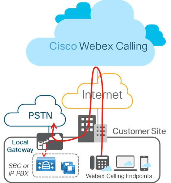
The figure below displays a Webex Calling deployment without any existing IP PBX and is applicable to a single or a multi-site deployment. Configuration outlined in this article is based on this deployment.
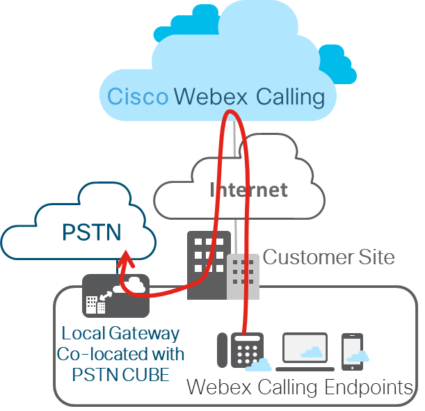
Layer 2 Box-to-Box Redundancy
CUBE HA layer 2 box-to-box redundancy uses the Redundancy Group (RG) infrastructure protocol to form an active/standby pair of routers. This pair share the same virtual IP address (VIP) across their respective interfaces and continually exchange status messages. CUBE session information is check-pointed across the pair of routers enabling the standby router to take all CUBE call processing responsibilities over immediately if the active router goes out of service, resulting in stateful preservation of signaling and media.
Check pointing is limited to connected calls with media packets. Calls in transit are not check pointed (for example, a trying or ringing state).
In this article, CUBE HA will refer to CUBE High Availability (HA) Layer 2 Box-to-box (B2B) redundancy for stateful call preservation
As of IOS-XE 16.12.2, CUBE HA can be deployed as a Local Gateway for Cisco Webex Calling trunk (Premises-based PSTN) deployments and we’ll cover design considerations and configurations in this article. This figure displays a typical CUBE HA setup as Local Gateway for a Cisco Webex Calling trunk deployment.
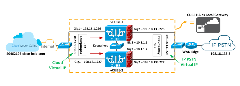
Redundancy Group Infra Component
The Redundancy Group (RG) Infra component provides the box-to-box communication infrastructure support between the two CUBEs and negotiates the final stable redundancy state. This component also provides:
-
An HSRP-like protocol that negotiates the final redundancy state for each router by exchanging keepalive and hello messages between the two CUBEs (via the control interface)—GigabitEthernet3 in the figure above.
-
A transport mechanism for checkpointing the signaling and media state for each call from the active to the standby router (via the data interface)—GigabitEthernet3 in the figure above.
-
Configuration and management of the Virtual IP (VIP) interface for the traffic interfaces (multiple traffic interfaces can be configured using the same RG group) – GigabitEthernet 1 and 2 are considered traffic interfaces.
This RG component has to be specifically configured to support voice B2B HA.
Virtual IP (VIP) Address Management for Both Signaling and Media
B2B HA relies on VIP to achieve redundancy. The VIP and associated physical interfaces on both CUBEs in the CUBE HA pair must reside on the same LAN subnet. Configuration of the VIP and binding of the VIP interface to a particular voice application (SIP) are mandatory for voice B2B HA support. External devices such as Unified CM, Webex Calling access SBC, service provider, or proxy, use VIP as the destination IP address for the calls traversing through the CUBE HA routers. Hence, from a Webex Calling point of view, the CUBE HA pairs acts as a single local gateway.
The call signaling and RTP session information of established calls are checkpointed from the active router to the standby router. When the Active router goes down, the Standby router takes over, and continues to forward the RTP stream that was previously routed by the first router.
Calls in a transient state at the time of failover will not be preserved post-switchover. For example, calls that aren't fully established yet or are in the process of being modified with a transfer or hold function. Established calls may be disconnected post-switchover.
The following requirements exist for using CUBE HA as a local gateway for stateful failover of calls:
-
CUBE HA cannot have TDM or analog interfaces co-located
-
Gig1 and Gig2 are referred to as traffic (SIP/RTP) interfaces and Gig3 is Redundancy Group (RG) Control/data interface
-
No more than 2 CUBE HA pairs can be placed in the same layer 2 domain, one with group id 1 and the other with group id 2. If configuring 2 HA pairs with the same group id, RG Control/Data interfaces needs to belong to different layer 2 domains (vlan, separate switch)
-
Port channel is supported for both RG Control/data and traffic interfaces
-
All signaling/media is sourced from/to the Virtual IP Address
-
Anytime a platform is reloaded in a CUBE-HA relationship, it always boots up as Standby
-
Lower address for all the interfaces (Gig1, Gig2, Gig3) should be on the same platform
-
Redundancy Interface Identifier, rii should be unique to a pair/interface combination on the same Layer 2
-
Configuration on both the CUBEs must be identical including physical configuration and must be running on the same type of platform and IOS-XE version
-
Loopback interfaces cannot be used as bind as they are always up
-
Multiple traffic (SIP/RTP) interfaces (Gig1, Gig2) require interface tracking to be configured
-
CUBE-HA is not supported over a crossover cable connection for the RG-control/data link (Gig3)
-
Both platforms must be identical and be connected via a physical Switch across all likewise interfaces for CUBE HA to work, i.e. GE0/0/0 of CUBE-1 and CUBE-2 must terminate on the same switch and so on.
-
Cannot have WAN terminated on CUBEs directly or Data HA on either side
-
Both Active/Standby must be in the same data center
-
It is mandatory to use separate L3 interface for redundancy (RG Control/data, Gig3). i.e interface used for traffic cannot be used for HA keepalives and checkpointing
-
Upon failover, the previously active CUBE goes through a reload by design, preserving signaling and media
Configure Redundancy on Both CUBEs
You must configure layer 2 box-to-box redundancy on both CUBEs intended to be used in an HA pair to bring up virtual IPs.
| 1 |
Configure interface tracking at a global level to track the status of the interface.
Track CLI is used in RG to track the voice traffic interface state so that the active route will quite its active role after the traffic interface is down. | ||
| 2 |
Configure an RG for use with VoIP HA under the application redundancy sub-mode.
Here's an explanation of the fields used in this configuration:
| ||
| 3 |
Enable box-to-box redundancy for the CUBE application. Configure the RG from the previous step under
redundancy-group 1—Adding and removing this command requires a reload for the updated configuration to take effect. We'll reload the platforms after all the configuration has been applied. | ||
| 4 |
Configure the Gig1 and Gig2 interfaces with their respective virtual IPs as shown below and apply the redundancy interface identifier (rii)
Here's an explanation of the fields used in this configuration:
| ||
| 5 |
Save the configuration of the first CUBE and reload it. The platform to reload last is always the Standby.
After VCUBE-1 boots up completely, save the configuration of VCUBE-2 and reload it.
| ||
| 6 |
Verify that the box-to-box configuration is working as expected. Relevant output is highlighted in bold. We reloaded VCUBE-2 last and as per the design considerations; the platform to reload last will always be Standby. |
Configure a Local Gateway on Both CUBEs
In our example configuration, we’re using the following trunk information from Control Hub to build the Local Gateway configuration on both the platforms, VCUBE-1 and VCUBE-2. The username and password for this setup are as follows:
-
Username: Hussain1076_LGU
-
Password: lOV12MEaZx
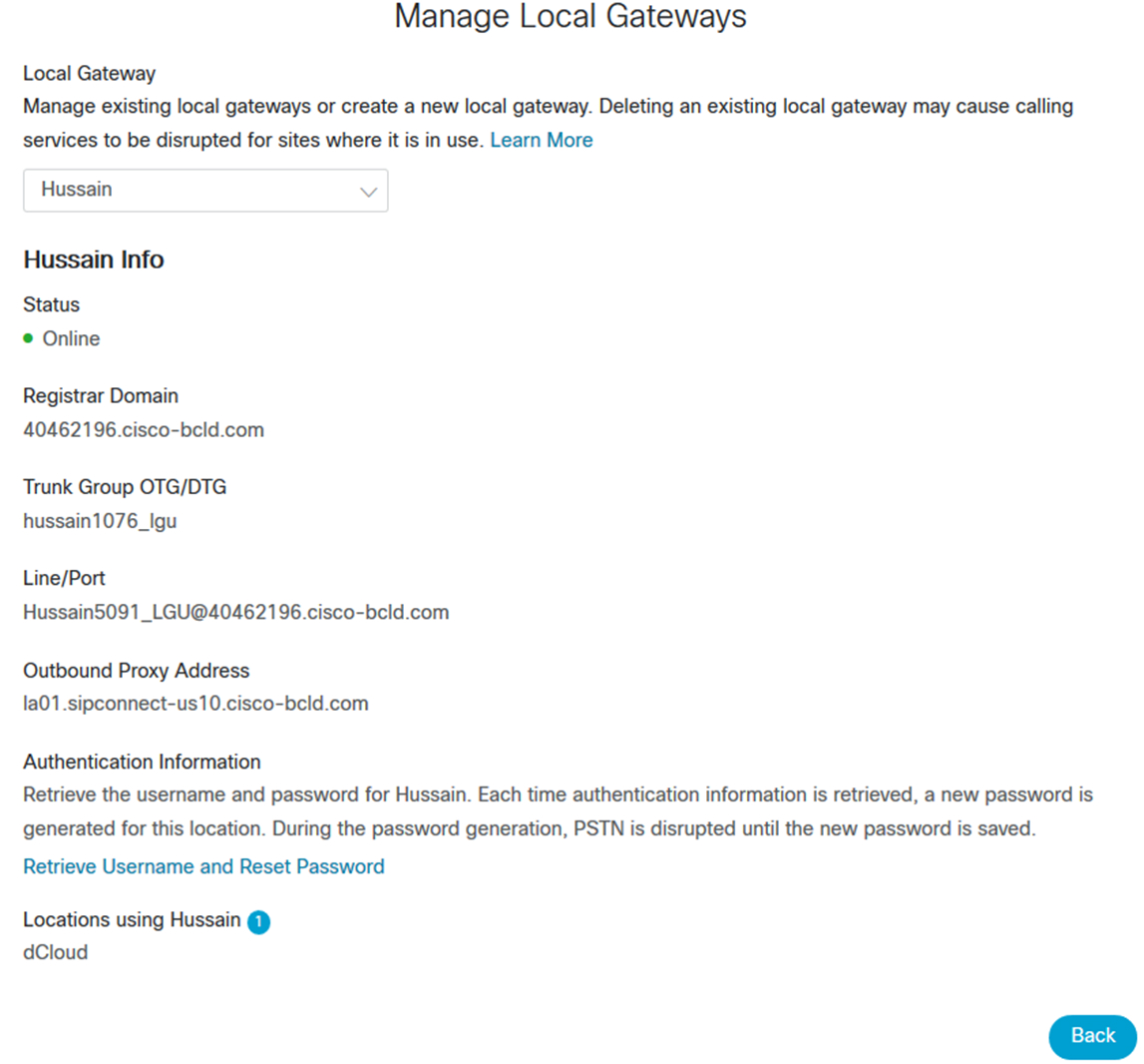
| 1 |
Ensure that a configuration key is created for the password, with the commands shown below, before it can be used in the credentials or shared secrets. Type 6 passwords are encrypted using AES cipher and this user-defined configuration key.
Here is the Local Gateway configuration that will apply to both platforms based on the Control Hub parameters displayed above, save and reload. SIP Digest credentials from Control Hub are highlighted in bold.
To display the show command output, we've reloaded VCUBE-2 followed by VCUBE-1, making VCUBE-1 the standby CUBE and VCUBE-2 the active CUBE |
| 2 |
At any given time, only one platform will maintain an active registration as the Local Gateway with the Webex Calling access SBC. Take a look at the output of the following show commands. show redundancy application group 1 show sip-ua register status
From the output above, you can see that VCUBE-2 is the active LGW maintaining the registration with Webex Calling access SBC, whereas the output of the “show sip-ua register status” is blank in VCUBE-1 |
| 3 |
Now enable the following debugs on VCUBE-1
|
| 4 |
Simulate failover by issuing the following command on the active LGW, VCUBE-2 in this case.
Switchover from the ACTIVE to the STANDBY LGW occurs in the following scenario as well besides the CLI listed above
|
| 5 |
Check to see if VCUBE-1 has registered with Webex Calling access SBC. VCUBE-2 would have reloaded by now.
VCUBE-1 is now the active LGW. |
| 6 |
Look at the relevant debug log on VCUBE-1 sending a SIP REGISTER to Webex Calling VIA the virtual IP and receiving a 200 OK.
|
Configure Webex Calling for your organization
Set up calling settings in First Time Setup Wizard
The first step to get your Webex Calling services up and running is to complete the First Time Setup Wizard (FTSW). Once the FTSW is completed for your first location, it doesn’t need to be completed for additional locations.
| 1 |
Click the Getting Started link in the Welcome email you receive. Your administrator email address is automatically used to sign in to Control Hub, where you'll be prompted to create your administrator password. After you sign in, the setup wizard automatically starts. |
| 2 |
Review and accept the terms of service. |
| 3 |
Review your plan and then click Get Started. Your account manager is responsible for activating the first steps for FTSW. Contact your account manager if you receive a “Cannot Setup Your Call” notice, when you select Get Started. |
| 4 |
Select the country that your data center should map to, and enter the customer contact and customer address information. |
| 5 |
Click Next: Default Location. |
| 6 |
Choose from the following options:
After you complete the setup wizard make sure you add a main number to the location you create. |
| 7 |
Make the following selections to apply to this location:
|
| 8 |
Click Next. |
| 9 |
Enter an available Cisco Webex SIP address and click Next and select Finish. |
Add a location
Before you begin
To create a new location, prepare the following information:
-
Location address
-
Desired phone numbers (optional)
| 1 |
Log in to Control Hub at https://admin.webex.com, go to . A new location will be hosted in the regional data center that corresponds to the country you selected using the First Time Setup Wizard. |
| 2 |
Configure the settings of the location:
|
| 3 |
Click Save and then choose Yes/ No to add numbers to the location now or later. |
| 4 |
If you clicked Yes, choose one of the following options:
The choice of PSTN option is at each location level (each location has only one PSTN option). You can mix and match as many options as you’d like for your deployment, but each location will have one option. Once you’ve selected and provisioned a PSTN option, you can change it by clicking Manage in the location PSTN properties. Some options, such as Cisco PSTN, however, may not be available after another option has been assigned. Open a support case for guidance. |
| 5 |
Choose whether you want to activate the numbers now or later. |
| 6 |
If you selected non-integrated CCP or Premises-based PSTN, enter Phone Numbers as comma-separated values, and then click Validate. Numbers are added for the specific location. Valid entries move to the Validated Numbers field, and invalid entries remain in the Add Numbers field accompanied by an error message. Depending on the location's country, the numbers are formatted according to local dialing requirements. For example, if a country code is required, you can enter numbers with or without the code and the code is prepended. |
| 7 |
Click Save. |
What to do next
After you create a location, you can enable emergency 911 services for that location. See RedSky Emergency 911 Service for Webex Calling for more information.
Delete a location
Before you begin
You can delete a location that's either not in use or was configured incorrectly after deleting the users and Workspaces associated with it. When you delete a location, you delete all the assigned services and numbers.
Get a list of the users and workspaces associated with a location: Go to and from the drop-down menu, select the location to delete. You must delete those users and workspaces before you delete the location.
Keep in mind that any numbers associated with this location are released back to your PSTN provider; you'll no longer own those numbers.
| 1 |
Log in to the Control Hub at https://admin.webex.com, go to . |
| 2 |
Click |
| 3 |
Choose Delete Location, and confirm that you want to delete that location. It typically takes a couple of minutes to permanently delete the location, but can take up to an hour. You can check the status by clicking |
Update an existing location
You can change your PSTN setup, the name, time zone, and language of a location after it's created. Keep in mind though that the new language only applies to new users and devices. Existing users and devices continue to use the old language.
For existing locations, you can enable emergency 911 services. See RedSky Emergency 911 Service for Webex Calling for more information.
| 1 |
Sign in to Control Hub. |
| 2 |
Go to . If you see a Caution symbol next to a location, it means that you haven't configured a telephone number for that location yet. You can't make or receive any calls until you configure that number. |
| 3 |
(Optional) Under PSTN Connection, select either Cloud Connected PSTN or Premises-based PSTN (local gateway), depending on which one you've already configured. Click Manage to change that configuration, and then acknowledge the associated risks by selecting Continue. Then, choose one of the following options and click Save:
To migrate, refer Migrate to Cisco Calling plans below. |
| 4 |
For the location, select the Main Number from the drop-down list. The main number can be assigned to an auto attendant or other destination within the location so external callers are routed to an appropriate destination. It’s mandatory to assign a main number to the location if it has any trunks or any extension-only entities, such as users, workspaces, virtual lines, or features. Without a main number, the trunks aren't usable and extension-only entities can't make or receive internal or external calls. Users in that location can also use this number as their external caller ID when making PSTN calls. If you choose a toll-free number as the main number for a location, we recommend updating the Emergency Callback Number for the location because a toll-free number doesn’t have an emergency services address. For more information, see Configure Emergency Callback Number for a Location. |
| 5 |
(Optional) Under Emergency Calling, you can select Emergency Location Identifier to assign to this location. This setting is optional and is only applicable for countries that require it. In some countries (Example: France), regulatory requirements exist for cellular radio systems to establish the identity of the cell when you make an emergency call and is made available to the emergency authorities. Other countries like the U.S and Canada implement location determination using other methods. For more information, see Enhanced Emergency Calling. Your emergency call provider may need information about the access network and this is achieved by defining a new private SIP extension header, P-Access-Network-Info. The header carries information relating to the access network. When you set the Emergency Location Identifier for a Location, the location value is sent to the provider as part of the SIP message. Contact your emergency call provider to see if you require this setting and use the value that is provided by your emergency call provider." |
| 6 |
Select the Voicemail Number that users can call to check their voicemail for this location. |
| 7 |
(Optional) Click the pencil icon at the top of the Location page to change the Location Name, Announcement Language, Email Language, Time Zone, or Address as needed, and then click Save. Changing the Announcement Language takes effect immediately for any new users and features added to this location. If existing users and/or features should also have their announcement language changed, when prompted, select Change for existing users and workspaces or Change for existing features. Click Apply. You can view progress on the Tasks page. You can't make any more changes until this is complete. Changing the Time Zone for a location doesn't update the time zones of the features associated with the location. To edit the time zones for features like auto attendant, hunt group, and call queue, go to the General Settings area of the specific feature you want to update the time zone for and edit and save there. |
Migrate to Cisco Calling plans
You can change your PSTN connection for an existing location to Cisco PSTN. For example, you can change the locations for the premises-based PSTN (local gateway) or nonintegrated CCP connections to Cisco PSTN. Cisco PSTN provides a cloud PSTN solution from Cisco.
All portable numbers remain functional except for a small interruption during the scheduled porting completion time.
Also, you can’t make any number management change for a location that’s undergoing a PSTN connection transition. But the existing numbers remain functional and you can still assign or unassign numbers to the location. You can’t add, delete, and move in or out numbers for that location. During this process, the routing profile automatically updates, enabling Cisco PSTN.
Currently, the capability of changing PSTN connection for an existing location to Cisco PSTN isn’t supported for the Japan region.
While changing the PSTN connection, a subscription with a calling license is applied, and the billing service receives a notification.
Limitations:
-
Migration from an integrated IntelePeer location to a Cisco PSTN location isn’t supported
-
Dedicated Instance location can’t be migrated into Cisco PSTN
-
Multiple port orders may be required for the PSTN connection change. If so, these orders are linked so they complete at the same time. Any date change or cancellation of one port order must be applied to all linked port orders for the connection change.
How to initiate a PSTN connection change
| 1 |
Sign in to Control Hub. |
| 2 |
Go to . |
| 3 |
Select the location for that you want to change the PSTN connection to Cisco PSTN. |
| 4 |
Go to the Calling tab, click the Manage option next to the Premises-based PSTN or nonintegrated Cloud Connected PSTN. |
| 5 |
Edit next to Connection Type. |
| 6 |
Select the Cisco Calling Plans card and choose the subscription that allocates Cisco Calling Plan for users at this location. Click Next. |
| 7 |
A connection change page appears for your confirmation. Click Next and check port readiness for your numbers. The Next button enables only if all numbers in the list are portable. Read these pointers:
|
| 8 |
Click Next and provide the contract information. This is the primary contract contact for all locations using Cisco Calling Plans (U.S.). Any changes to this contact apply to all other locations using Cisco Calling Plans (U.S.). |
| 9 |
Click Next. A notification displays asking for your confirmation to save your contract information for that location. Select Yes, change. |
| 10 |
Provide the emergency service address and click Save. In an emergency, the local emergency response team uses this address to locate the caller. |
| 11 |
The summary page appears with the number of ports created. If there’s only one order, you can see an additional step called Provide additional information. For multiple orders, an order selector is available at the top to navigate between them. Click Next and enter the details to complete the port wizard. The orders are submitted at once when all information is provided for a single PSTN migration request. By default, the firm order commitment date is consistent across all orders. The PSTN connection change automatically applies after the last linked order is ported completely.
The migration details are available under the tab. Select the order ID to view the order details in a side-panel view. You can see the type as Change PSTN for the orders created from PSTN connection change. |
Cancel the PSTN connection change
An administrator can cancel the PSTN migration when the location is still in a transition state.
| 1 |
Sign in to Control Hub. |
| 2 |
Go to . |
| 3 |
Select the location for that you want to cancel the PSTN connection. |
| 4 |
Go to the Calling tab, click the Cancel PSTN connection change button. |
| 5 |
Click Yes, continue to confirm the cancellation. |
Configure Webex Calling dial plan
You can control the dial plan for your Webex Calling deployment with outbound dialing codes. Customize extension lengths, routing prefixes, and dialing preferences (internal and external) to be compatible with the dialing habits of your users.
These settings are for internal dialing and are also available in the first-time setup wizard. As you change your dial plan, the example numbers in the Control Hub update to show these changes.
You can configure outgoing Calling permissions for a location. See these steps to configure outgoing Calling permissions.
| 1 |
Sign in to Control Hub, go to , and then scroll to Internal Dialing. |
| 2 |
Configure the following optional dialing preferences, as needed:
|
| 3 |
Specify internal dialing for specific locations. Go to , select a location from the list, and click Calling. Scroll to Dialing, and then change internal dialing as needed:
|
| 4 |
Specify external dialing for specific locations. Go to , select a location from the list, and click Calling. Scroll to Dialing, and then change external dialing as needed:
Impact to users:
|
Configure premises-based PSTN (Local Gateway) in Control Hub
If you're a value added reseller, you can use these steps to start local gateway configuration in Control Hub. When this gateway is registered to the cloud, you can use it on one or more of your Webex Calling locations to provide routing toward an enterprise PSTN service provider.
A location that has a local gateway can't be deleted when the local gateway is being used for other locations.
Create a trunk
Before you begin
-
Once a location is added, and before configuring premises-based PSTN for a location, you must create a trunk.
-
Create any locations and specific settings and numbers to each one. Locations must exist before you can add a premises-based PSTN.
-
Understand the Premises-based PSTN (local gateway) requirements for Webex Calling.
-
You can't choose more than one trunk for a location with premises-based PSTN, but you can choose the same trunk for multiple locations.
| 1 |
Log in to Control Hub at https://admin.webex.com, go to , and select Add Trunk. |
| 2 |
Select a location. |
| 3 |
Name the trunk and click Save. The name can't be longer than 24 characters. |
What to do next
Trunk information appears on the screen Register Domain, Trunk Group OTG/DTG, Line/Port, and Outbound Proxy Address.
We recommend that you copy this information from Control Hub and paste it into a local text file or document so you can refer to it when you're ready to configure the premises-based PSTN.
If you lose the credentials, you must generate them from the trunk information screen in Control Hub. Click Retrieve Username and Reset Password to generate a new set of authentication credentials to use on the trunk.
Select a trunk for Premises-based PSTN
| 1 |
Log in to Control Hub at https://admin.webex.com, go to . |
| 2 |
Select a location to modify and click Manage. |
| 3 |
Select Premises-based PSTN and click Next. |
| 4 |
Choose a trunk from the drop-down menu. Visit the trunk page to manage your trunk group choices. |
| 5 |
Click the confirmation notice, then click Save. |
What to do next
You must take the configuration information that Control Hub generated and map the parameters into the local gateway (for example, on a Cisco CUBE that sits on the premises). This article walks you through this process. As a reference, see the following diagram for an example of how the Control Hub configuration information (on the left) maps onto parameters in the CUBE (on the right):
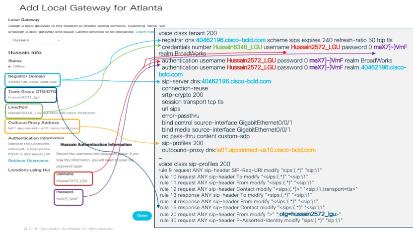
After you successfully complete the configuration on the gateway itself, you can return to in Control Hub and the gateway that you created will be listed in the location card that you assigned it to with a green dot to the left of the name. This status indicates that the gateway is securely registered to the calling cloud and is serving as the active PSTN gateway for the location.
Manage phone numbers
You can easily view, activate, remove and add phone numbers for your organization in Control Hub. For more information, see Manage phone numbers in Control Hub.
Request a Webex services purchase from a trial in Control Hub
If you're trying out Webex services and you'd like to convert your trial to a paid subscription, you can submit an email request to your partner.
| 1 |
Log in to Control Hub at https://admin.webex.com, select the building icon |
| 2 |
Select the Subscriptions tab, and then click Purchase Now. An email is sent to your partner letting them know that you're interested in converting to a paid subscription. |
Set calling options
You can use Control Hub to set the priority of available calling options that users see in Webex App. You can also enable them for single click-to-call. For more information, see: Set calling options for Webex App users.
Set up calling behavior
You can control what calling application opens when users make calls. You can configure the calling client settings, including mixed-mode deployment for organizations with users entitled with Unified CM or Webex Calling and users without paid calling services from Cisco. For more information, see: Set up calling behavior.
Configure Unified CM for Webex Calling
Configure SIP Trunk Security Profile for Trunk to Local Gateway
In cases where Local Gateway and PSTN gateway reside on the same device, Unified CM must be enabled to differentiate between two different traffic types (calls from Webex and from the PSTN) that are originating from the same device and apply differentiated class of service to these call types. This differentiated call treatment is achieved by provisioning two trunks between Unified CM and the combined local gateway and PSTN gateway device which requires different SIP listening ports for the two trunks.
|
Create a dedicated SIP Trunk Security Profile for the Local Gateway trunk with the following settings:
| ||||||||||
Configure SIP Profile for the Local Gateway Trunk
|
Create a dedicated SIP Profile for the Local Gateway trunk with the following settings:
| ||||||||||
Create a Calling Search Space for Calls From Webex
|
Create a calling search space for calls originating from Webex with the following settings:
The last partition onNetRemote is only used in a multi-cluster environment where routing information is exchanged between Unified CM clusters using Intercluster Lookup Service (ILS) or Global Dialplan Replication (GDPR). | ||||||||||
Configure a SIP Trunk To and From Webex
|
Create a SIP trunk for the calls to and from Webex via the Local Gateway with the following settings:
| ||||||||||||||||||||||||||
Configure Route Group for Webex
|
Create a route group with the following settings:
| ||||||||
Configure Route List for Webex
|
Create a route list with the following settings:
| ||||||||||||||
Create a Partition for Webex Destinations
|
Create a partition for the Webex destinations with the following settings:
| ||||||||
What to do next
Make sure to add this partition to all calling search spaces that should have access to Webex destinations. You must add this partition specifically to the calling search space that is used as the inbound calling search space on PSTN trunks, so that calls from the PSTN to Webex can be routed.
Configure Route Patterns for Webex Destinations
|
Configure route patterns for each DID range on Webex with the following settings:
| ||||||||||||
Configure Abbreviated Intersite Dialing Normalization for Webex
|
If abbreviated inter-site dialing is required to Webex, then configure dialing normalization patterns for each ESN range on Webex with the following settings:
| ||||||||||||||||||
Set up your Webex Calling features
Set up a hunt group
Hunt groups route incoming calls to a group of users or workspaces. You can even configure a pattern to route to a whole group.
For more information on how to set up a hunt group, see Hunt Groups in Cisco Webex Control Hub.
Create a call queue
You can set up a call queue so that when customers' calls can't be answered, they're provided with an automated answer, comfort messages, and music on hold until someone can answer their call.
For more information on how to set up and manage a call queue, see Manage Call Queues in Cisco Webex Control Hub.
Create a receptionist client
Help support the needs of your front-office personnel. You can set up users as telephone attendants so they can screen incoming calls to certain people within your organization.
For information about how to set up and view your receptionist clients, see Receptionist Clients in Cisco Webex Control Hub.
Create and manage auto attendants
You can add greetings, set up menus, and route calls to an answering service, a hunt group, a voicemail box, or a real person. Create a 24-hour schedule or provide different options when your business is open or closed.
For information about how to create and manage auto attendants, see Manage Auto Attendants in Cisco Webex Control Hub.
Configure a paging group
Group paging allows a user to place a one-way call or group page to up to 75 target users and workspaces by dialing a number or extension assigned to a specific paging group.
For information about how to set up and edit paging groups, see Configure a Paging Group in Cisco Webex Control Hub.
Set up call pickup
Enhance teamwork and collaboration by creating a call pickup group so users can answer each others calls. When you add users to a call pickup group and a group member is away or busy, another member can answer their calls.
For information about how to set up a call pickup group, see Call Pickup in Cisco Webex Control Hub.
Set up call park
Call park allows a defined group of users to park calls against other available members of a call park group. Parked calls can be picked up by other members of the group on their phone.
For more information about how to set up call park, see Call Park in Cisco Webex Control Hub.
Enable barge-in for users
| 1 |
Sign in to Control Hub. |
| 2 |
Go to . |
| 3 |
Select a user and click Calling. |
| 4 |
Go to the Between-user permissions section, and then select Barge in. |
| 5 |
Turn on the toggle to allow other users to add themselves to this user's ongoing call. |
| 6 |
Check Play a tone when this user Barges In on a call if you want to play a tone to others when this user barges in on their call. The Play a tone when this user Barges In on a call setting doesn't apply to Customer Experience Basic and Essentials supervisor barge-in functionality. Even if you enable this option for a supervisor, the system doesn't play the notification tone to the agent when a supervisor barges in on their call queue call. If you want to play a tone to an agent when a supervisor barges in on their call, you can enable it through ‘Notification tone for agents’ settings. For more information, see the Create a queue section in Webex Customer Experience Basic or Webex Customer Experience Essentials. |
| 7 |
Click Save. |
Enable privacy for a user
| 1 |
Sign in to Control Hub, and go to . |
| 2 |
Choose a user and click Calling. |
| 3 |
Go to the Between-user Permissions area and then choose Privacy. |
| 4 |
Choose the appropriate Auto Attendant Privacy settings for this user.
|
| 5 |
Check the Enable Privacy check box. You can then decide to block everyone by not choosing members from the drop-down list. Alternatively, you can choose the users, workspaces, and virtual lines that can monitor the line status of this user. If you're a location administrator, only the users, workspaces, and virtual lines pertaining to your assigned locations appear in the drop-down list. Uncheck the Enable Privacy check box to allow everyone to monitor the line status. |
| 6 |
Check the Enforce privacy for directed call pickup and barge-in check box to enable privacy for directed call pickup and barge-in.
|
| 7 |
From Add member by name, choose the users, workspaces, and virtual lines that can monitor the phone line status and invoke directed call pickup and barge-in. |
| 8 |
To filter the members that you select, use the filter by name, number or ext field. |
| 9 |
Click Remove All to remove all the selected members. To remove an individual member, click Delete next to the member's name. |
| 10 |
Click Save. |
Configure monitoring
The maximum number of monitored lines for a user is 50. However, while configuring the monitoring list, consider the number of messages that impact the bandwidth between Webex Calling and your network. Also, determine the maximum monitored lines by the number of line buttons on the user's phone.
| 1 |
From the customer view in https://admin.webex.com, go to Management and then click Users. |
| 2 |
Select the user you want to modify and click Calling. |
| 3 |
Go to Between-user Permissions section, and select Monitoring. |
| 4 |
Choose from the following:
You can include a virtual line in the Add Monitored Line list for user monitoring. |
| 5 |
Choose if you wish to notify this user about parked calls, search for the person or call park extension to be monitored, and then click Save. The monitored lines list in Control Hub corresponds with the order of monitored lines that show on the user’s device. You can reorder the list of monitored lines at any time. The name that appears for the monitored line is the name entered in the Caller ID First Name and Last Name fields for the user, workspace, and virtual line. |
Enable call bridge warning tone for users
Before you begin
| 1 |
Sign in to Control Hub, and go to . |
| 2 |
Select a user and click the Calling tab. |
| 3 |
Go to Between-user Permissions, and click Call Bridging Warning Tone. |
| 4 |
Turn on Call Bridging Warning Tone, and then click Save. By default, this feature is enabled. For more information on call bridging on an MPP shared line, see Shared lines on your multiplatform desk phone. For more information on call bridging on a Webex App shared line, see Shared line appearance for WebexApp. |
Turn on hoteling for a user
Enabling hoteling for a user allows them to use a host phone while maintaining the functionality and features of their main desk phone.
| 1 |
Sign in to Control Hub. |
| 2 |
Go to . |
| 3 |
Select a user and click the Calling tab. |
| 4 |
Go to the Between-user permissions section, select Hoteling, and turn on the toggle. |
| 5 |
Enter the name or number of the hoteling host in the Hoteling Location search field and choose the hoteling host that you want to assign to the user. You can select only one hoteling host. If you choose another hoteling host, the first one gets deleted. If you're a location administrator, you can assign only the hoteling host pertaining to your assigned locations. |
| 6 |
Choose the number of hours the user can use the hoteling host from the Limit Association Period drop-down. The phone automatically logs out the user after the chosen time. An error message displays on the screen if the limit association period specified for the user exceeds the limit association period of the chosen hoteling host. For example, if the hoteling host has a limit association period of 12 hours and the user's limit association period is 24 hours, an error message displays. In such cases, you need to extend the limit association period of the hoteling host if the user needs more time. |
| 7 |
Click Save. A user can also search and locate the hoteling host they want to use from the User Hub. For more information, see Access your calling profile from anywhere. |
Want to see how it's done? Watch this video demonstration on how to configure hoteling in the Control Hub.
Adoption trends and usage reports for Webex Calling
View calling reports
You can use the Analytics page in Control Hub to view how Webex Calling services are used, engagement in the Webex app, and the quality of their call media experience. To access Webex Calling analytics:
| 1 |
Sign in to Control Hub. |
| 2 |
Go to Analytics and select the Calling tab. |
| 3 |
Select Detailed Call History. The calling history details are displayed with media quality data.
|
| 4 |
To access media quality data, sign in to Control Hub, then go to Analytics and then select Calling. |


