Fundamentals

Prerequisites

Before you deploy CUBE HA as a local gateway for Webex Calling, make sure you have an in-depth understanding of the following concepts:

The configuration guidelines provided in this article assume a dedicated local gateway platform with no existing voice configuration. If an existing CUBE enterprise deployment is being modified to also utilize the local gateway function for Cisco Webex Calling, pay close attention to the configuration applied to ensure existing call flows and functionalities are not interrupted and make sure you're adhering to CUBE HA design requirements.

Hardware and Software Components

CUBE HA as local gateway requires IOS-XE version 16.12.2 or later and a platform on which both CUBE HA and LGW functions are supported.

The show commands and logs in this article are based on minimum software release of Cisco IOS-XE 16.12.2 implemented on a vCUBE (CSR1000v).

Reference Material

Here are some detailed CUBE HA configuration guides for various platforms:

Webex Calling Solution Overview

Cisco Webex Calling is a collaboration offering that provides a multi-tenant cloud-based alternative to on-premise PBX phone service with multiple PSTN options for customers.

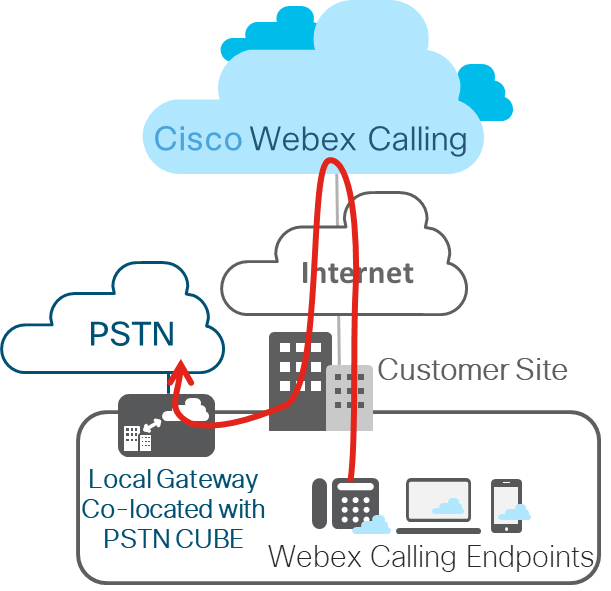
The Local Gateway deployment (represented below) is the focus of this article. Local gateway (Premises-based PSTN) trunk in Webex Calling allows connectivity to a customer-owned PSTN service. It also provides connectivity to an on-premises IP PBX deployment such as Cisco Unified CM. All communication to and from the cloud is secured using TLS transport for SIP and SRTP for media.
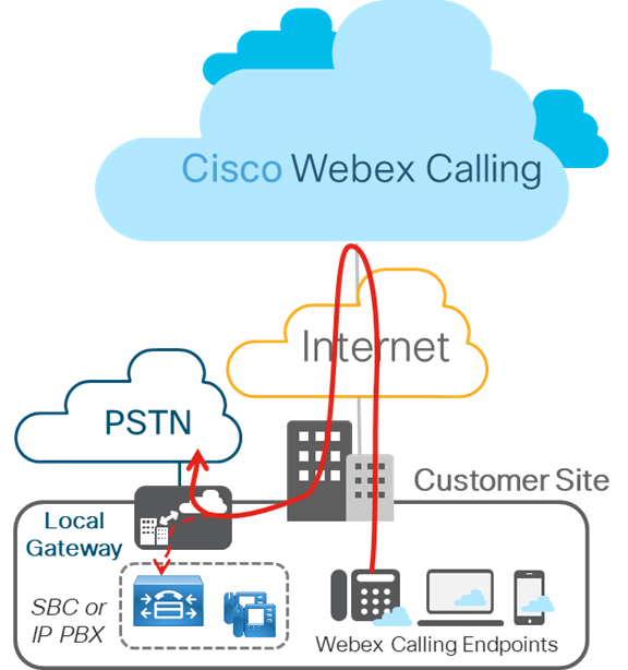
The figure below displays a Webex Calling deployment without any existing IP PBX and is applicable to a single or a multi-site deployment. Configuration outlined in this article is based on this deployment.
Layer 2 Box-to-Box Redundancy

CUBE HA layer 2 box-to-box redundancy uses the Redundancy Group (RG) infrastructure protocol to form an active/standby pair of routers. This pair share the same virtual IP address (VIP) across their respective interfaces and continually exchange status messages. CUBE session information is check-pointed across the pair of routers enabling the standby router to take all CUBE call processing responsibilities over immediately if the active router goes out of service, resulting in stateful preservation of signaling and media.

Check pointing is limited to connected calls with media packets. Calls in transit are not check pointed (for example, a trying or ringing state).

In this article, CUBE HA will refer to CUBE High Availability (HA) Layer 2 Box-to-box (B2B) redundancy for stateful call preservation

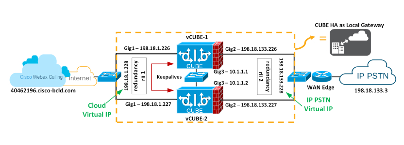
As of IOS-XE 16.12.2, CUBE HA can be deployed as a Local Gateway for Cisco Webex Calling trunk (Premises-based PSTN) deployments and we’ll cover design considerations and configurations in this article. This figure displays a typical CUBE HA setup as Local Gateway for a Cisco Webex Calling trunk deployment.
Redundancy Group Infra Component

The Redundancy Group (RG) Infra component provides the box-to-box communication infrastructure support between the two CUBEs and negotiates the final stable redundancy state. This component also provides:

  • An HSRP-like protocol that negotiates the final redundancy state for each router by exchanging keepalive and hello messages between the two CUBEs (via the control interface)—GigabitEthernet3 in the figure above.

  • A transport mechanism for checkpointing the signaling and media state for each call from the active to the standby router (via the data interface)—GigabitEthernet3 in the figure above.

  • Configuration and management of the Virtual IP (VIP) interface for the traffic interfaces (multiple traffic interfaces can be configured using the same RG group) – GigabitEthernet 1 and 2 are considered traffic interfaces.

This RG component has to be specifically configured to support voice B2B HA.

Virtual IP (VIP) Address Management for Both Signaling and Media

B2B HA relies on VIP to achieve redundancy. The VIP and associated physical interfaces on both CUBEs in the CUBE HA pair must reside on the same LAN subnet. Configuration of the VIP and binding of the VIP interface to a particular voice application (SIP) are mandatory for voice B2B HA support. External devices such as Unified CM, Webex Calling access SBC, service provider, or proxy, use VIP as the destination IP address for the calls traversing through the CUBE HA routers. Hence, from a Webex Calling point of view, the CUBE HA pairs acts as a single local gateway.

The call signaling and RTP session information of established calls are checkpointed from the active router to the standby router. When the Active router goes down, the Standby router takes over, and continues to forward the RTP stream that was previously routed by the first router.

Calls in a transient state at the time of failover will not be preserved post-switchover. For example, calls that aren't fully established yet or are in the process of being modified with a transfer or hold function. Established calls may be disconnected post-switchover.

The following requirements exist for using CUBE HA as a local gateway for stateful failover of calls:

  • CUBE HA cannot have TDM or analog interfaces co-located

  • Gig1 and Gig2 are referred to as traffic (SIP/RTP) interfaces and Gig3 is Redundancy Group (RG) Control/data interface

  • No more than 2 CUBE HA pairs can be placed in the same layer 2 domain, one with group id 1 and the other with group id 2. If configuring 2 HA pairs with the same group id, RG Control/Data interfaces needs to belong to different layer 2 domains (vlan, separate switch)

  • Port channel is supported for both RG Control/data and traffic interfaces

  • All signaling/media is sourced from/to the Virtual IP Address

  • Anytime a platform is reloaded in a CUBE-HA relationship, it always boots up as Standby

  • Lower address for all the interfaces (Gig1, Gig2, Gig3) should be on the same platform

  • Redundancy Interface Identifier, rii should be unique to a pair/interface combination on the same Layer 2

  • Configuration on both the CUBEs must be identical including physical configuration and must be running on the same type of platform and IOS-XE version

  • Loopback interfaces cannot be used as bind as they are always up

  • Multiple traffic (SIP/RTP) interfaces (Gig1, Gig2) require interface tracking to be configured

  • CUBE-HA is not supported over a crossover cable connection for the RG-control/data link (Gig3)

  • Both platforms must be identical and be connected via a physical Switch across all likewise interfaces for CUBE HA to work, i.e. GE0/0/0 of CUBE-1 and CUBE-2 must terminate on the same switch and so on.

  • Cannot have WAN terminated on CUBEs directly or Data HA on either side

  • Both Active/Standby must be in the same data center

  • It is mandatory to use separate L3 interface for redundancy (RG Control/data, Gig3). i.e interface used for traffic cannot be used for HA keepalives and checkpointing

  • Upon failover, the previously active CUBE goes through a reload by design, preserving signaling and media

Configure Redundancy on Both CUBEs

You must configure layer 2 box-to-box redundancy on both CUBEs intended to be used in an HA pair to bring up virtual IPs.

1

Configure interface tracking at a global level to track the status of the interface.

conf t
 track 1 interface GigabitEthernet1 line-protocol
 track 2 interface GigabitEthernet2 line-protocol
 exit

VCUBE-1#conf t

VCUBE-1(config)#track 1 interface GigabitEthernet1 line-protocol

VCUBE-1(config-track)#track 2 interface GigabitEthernet2 line-protocol

VCUBE-1(config-track)#exit

VCUBE-2#conf t

VCUBE-2(config)#track 1 interface GigabitEthernet1 line-protocol

VCUBE-2(config-track)#track 2 interface GigabitEthernet2 line-protocol

VCUBE-2(config-track)#exit

Track CLI is used in RG to track the voice traffic interface state so that the active route will quite its active role after the traffic interface is down.

2

Configure an RG for use with VoIP HA under the application redundancy sub-mode.

redundancy
  application redundancy
   group 1
    name LocalGateway-HA
    priority 100 failover threshold 75
    control GigabitEthernet3 protocol 1
    data GigabitEthernet3
    timers delay 30 reload 60
    track 1 shutdown
    track 2 shutdown
    exit
   protocol 1
    timers hellotime 3 holdtime 10
   exit
  exit
 exit

VCUBE-1(config)#redundancy

VCUBE-1(config-red)#application redundancy

VCUBE-1(config-red-app)#group 1

VCUBE-1(config-red-app-grp)#name LocalGateway-HA

VCUBE-1(config-red-app-grp)#priority 100 failover threshold 75

VCUBE-1(config-red-app-grp)#control GigabitEthernet3 protocol 1

VCUBE-1(config-red-app-grp)#data GigabitEthernet3

VCUBE-1(config-red-app-grp)#timers delay 30 reload 60

VCUBE-1(config-red-app-grp)#track 1 shutdown

VCUBE-1(config-red-app-grp)#track 2 shutdown

VCUBE-1(config-red-app-grp)#exit

VCUBE-1(config-red-app)#protocol 1

VCUBE-1(config-red-app-prtcl)#timers hellotime 3 holdtime 10

VCUBE-1(config-red-app-prtcl)#exit

VCUBE-1(config-red-app)#exit

VCUBE-1(config-red)#exit

VCUBE-1(config)#

VCUBE-2(config)#redundancy

VCUBE-2(config-red)#application redundancy

VCUBE-2(config-red-app)#group 1

VCUBE-2(config-red-app-grp)#name LocalGateway-HA

VCUBE-2(config-red-app-grp)#priority 100 failover threshold 75

VCUBE-2(config-red-app-grp)#control GigabitEthernet3 protocol 1

VCUBE-1(config-red-app-grp)#data GigabitEthernet3

VCUBE-2(config-red-app-grp)#timers delay 30 reload 60

VCUBE-2(config-red-app-grp)#track 1 shutdown

VCUBE-2(config-red-app-grp)#track 2 shutdown

VCUBE-2(config-red-app-grp)#exit

VCUBE-2(config-red-app)#protocol 1

VCUBE-2(config-red-app-prtcl)#timers hellotime 3 holdtime 10

VCUBE-2(config-red-app-prtcl)#exit

VCUBE-2(config-red-app)#exit

VCUBE-2(config-red)#exit

VCUBE-2(config)#

Here's an explanation of the fields used in this configuration:

  • redundancy—Enters redundancy mode

  • application redundancy—Enters application redundancy configuration mode

  • group—Enters redundancy application group configuration mode

  • name LocalGateway-HA—Defines the name of the RG group

  • priority 100 failover threshold 75—Specifies the initial priority and failover thresholds for an RG

  • timers delay 30 reload 60—Configures the two times for delay and reload

    • Delay timer which is the amount of time to delay RG group’s initialization and role negotiation after the interface comes up – Default 30 seconds. Range is 0-10000 seconds

    • Reload—This is the amount of time to delay RG group initialization and role-negotiation after a reload – Default 60 seconds. Range is 0-10000 seconds

    • Default timers are recommended, though these timers may be adjusted to accommodate any additional network convergence delay that may occur during bootup/reload of the routers, in order to guarantee that the RG protocol negotiation takes place after routing in the network has converged to a stable point. For example, if it is seen after failover that it takes up to 20 sec for the new STANDBY to see the first RG HELLO packet from the new ACTIVE, then the timers should be adjusted to ‘timers delay 60 reload 120’ to factor in this delay.

  • control GigabitEthernet3 protocol 1—Configures the interface used to exchange keepalive and hello messages between the two CUBEs, and specifies the protocol instance that will be attached to a control interface and enters redundancy application protocol configuration mode

  • data GigabitEthernet3—Configures the interface used for checkpointing of data traffic

  • track—RG group tracking of interfaces

  • protocol 1—Specifies the protocol instance that will be attached to a control interface and enters redundancy application protocol configuration mode

  • timers hellotime 3 holdtime 10—Configures the two timers for hellotime and holdtime:

    • Hellotime— Interval between successive hello messages – Default 3 seconds. Range is 250 milliseconds-254 seconds

    • Holdtime—The interval between the receipt of a Hello message and the presumption that the sending router has failed. This duration has to be greater than the hello-time – Default 10 seconds. Range is 750 milliseconds-255 seconds

      We recommend that you configure the holdtime timer to be at least 3 times the value of the hellotime timer.

3

Enable box-to-box redundancy for the CUBE application. Configure the RG from the previous step under voice service voip. This enables the CUBE application to control the redundancy process.

voice service voip
   redundancy-group 1
   exit

VCUBE-1(config)#voice service voip

VCUBE-1(config-voi-serv)#redundancy-group 1


                        % Created RG 1 association with Voice B2B HA; reload the router for the new configuration to take effect
                      

VCUBE-1(config-voi-serv)# exit

VCUBE-2(config)#voice service voip

VCUBE-2(config-voi-serv)#redundancy-group 1


                        % Created RG 1 association with Voice B2B HA; reload the router for the new configuration to take effect
                      

VCUBE-2(config-voi-serv)# exit

redundancy-group 1—Adding and removing this command requires a reload for the updated configuration to take effect. We'll reload the platforms after all the configuration has been applied.

4

Configure the Gig1 and Gig2 interfaces with their respective virtual IPs as shown below and apply the redundancy interface identifier (rii)

VCUBE-1(config)#interface GigabitEthernet1

VCUBE-1(config-if)# redundancy rii 1

VCUBE-1(config-if)# redundancy group 1 ip 198.18.1.228 exclusive

VCUBE-1(config-if)# exit

VCUBE-1(config)#

VCUBE-1(config)#interface GigabitEthernet2

VCUBE-1(config-if)# redundancy rii 2

VCUBE-1(config-if)# redundancy group 1 ip 198.18.133.228 exclusive

VCUBE-1(config-if)# exit

VCUBE-2(config)#interface GigabitEthernet1

VCUBE-2(config-if)# redundancy rii 1

VCUBE-2(config-if)# redundancy group 1 ip 198.18.1.228 exclusive

VCUBE-2(config-if)# exit

VCUBE-2(config)#

VCUBE-2(config)#interface GigabitEthernet2

VCUBE-2(config-if)# redundancy rii 2

VCUBE-2(config-if)# redundancy group 1 ip 198.18.133.228 exclusive

VCUBE-v(config-if)# exit

Here's an explanation of the fields used in this configuration:

  • redundancy rii—Configures the redundancy interface identifier for the redundancy group. Required for generating a Virtual MAC (VMAC) address. The same rii ID value must be used on the interface of each router (ACTIVE/STANDBY) that has the same VIP.

    If there is more than one B2B pair on the same LAN, each pair MUST have unique rii IDs on their respective interfaces (to prevent collision). ‘show redundancy application group all’ should indicate the correct local and peer information.

  • redundancy group 1—Associates the interface with the redundancy group created in Step 2 above. Configure the RG group, as well as the VIP assigned to this physical interface.

    It is mandatory to use a separate interface for redundancy, that is, the interface used for voice traffic cannot be used as control and data interface specified in Step 2 above. In this example, Gigabit interface 3 is used for RG control/data

5

Save the configuration of the first CUBE and reload it.

The platform to reload last is always the Standby.

VCUBE-1#wr


                        Building configuration...


                        [OK]
                      

VCUBE-1#reload


                        Proceed with reload? [confirm]
                      

After VCUBE-1 boots up completely, save the configuration of VCUBE-2 and reload it.

VCUBE-2#wr


                        Building configuration...


                        [OK]
                      

VCUBE-2#reload


                        Proceed with reload? [confirm]
                      

6

Verify that the box-to-box configuration is working as expected. Relevant output is highlighted in bold.

We reloaded VCUBE-2 last and as per the design considerations; the platform to reload last will always be Standby.


VCUBE-1#show redundancy application group all
Faults states Group 1 info:
       Runtime priority: [100]
               RG Faults RG State: Up.
                       Total # of switchovers due to faults:           0
                       Total # of down/up state changes due to faults: 0
Group ID:1
Group Name:LocalGateway-HA
  
Administrative State: No Shutdown
Aggregate operational state: Up
My Role: ACTIVE
Peer Role: STANDBY
Peer Presence: Yes
Peer Comm: Yes
Peer Progression Started: Yes

RF Domain: btob-one
         RF state: ACTIVE
         Peer RF state: STANDBY HOT

RG Protocol RG 1
------------------
        Role: Active
        Negotiation: Enabled
        Priority: 100
        Protocol state: Active
        Ctrl Intf(s) state: Up
        Active Peer: Local
        Standby Peer: address 10.1.1.2, priority 100, intf Gi3
        Log counters:
                role change to active: 1
                role change to standby: 1
                disable events: rg down state 0, rg shut 0
                ctrl intf events: up 1, down 0, admin_down 0
                reload events: local request 0, peer request 0

RG Media Context for RG 1
--------------------------
        Ctx State: Active
        Protocol ID: 1
        Media type: Default
        Control Interface: GigabitEthernet3
        Current Hello timer: 3000
        Configured Hello timer: 3000, Hold timer: 10000
        Peer Hello timer: 3000, Peer Hold timer: 10000
        Stats:
            Pkts 1509, Bytes 93558, HA Seq 0, Seq Number 1509, Pkt Loss 0
            Authentication not configured
            Authentication Failure: 0
            Reload Peer: TX 0, RX 0
            Resign: TX 0, RX 0
    Standy Peer: Present. Hold Timer: 10000
            Pkts 61, Bytes 2074, HA Seq 0, Seq Number 69, Pkt Loss 0

VCUBE-1#

VCUBE-2#show redundancy application group all
Faults states Group 1 info:
       Runtime priority: [100]
               RG Faults RG State: Up.
                       Total # of switchovers due to faults:           0
                       Total # of down/up state changes due to faults: 0
Group ID:1
Group Name:LocalGateway-HA
  
Administrative State: No Shutdown
Aggregate operational state: Up
My Role: STANDBY
Peer Role: ACTIVE
Peer Presence: Yes
Peer Comm: Yes
Peer Progression Started: Yes

RF Domain: btob-one
         RF state: ACTIVE
         Peer RF state: STANDBY HOT

RG Protocol RG 1
------------------
        Role: Active
        Negotiation: Enabled
        Priority: 100
        Protocol state: Active
        Ctrl Intf(s) state: Up
        Active Peer: address 10.1.1.2, priority 100, intf Gi3
        Standby Peer: Local
        Log counters:
                role change to active: 1
                role change to standby: 1
                disable events: rg down state 0, rg shut 0
                ctrl intf events: up 1, down 0, admin_down 0
                reload events: local request 0, peer request 0

RG Media Context for RG 1
--------------------------
        Ctx State: Active
        Protocol ID: 1
        Media type: Default
        Control Interface: GigabitEthernet3
        Current Hello timer: 3000
        Configured Hello timer: 3000, Hold timer: 10000
        Peer Hello timer: 3000, Peer Hold timer: 10000
        Stats:
            Pkts 1509, Bytes 93558, HA Seq 0, Seq Number 1509, Pkt Loss 0
            Authentication not configured
            Authentication Failure: 0
            Reload Peer: TX 0, RX 0
            Resign: TX 0, RX 0
    Standy Peer: Present. Hold Timer: 10000
            Pkts 61, Bytes 2074, HA Seq 0, Seq Number 69, Pkt Loss 0

VCUBE-2#

Configure a Local Gateway on Both CUBEs

In our example configuration, we’re using the following trunk information from Control Hub to build the Local Gateway configuration on both the platforms, VCUBE-1 and VCUBE-2. The username and password for this setup are as follows:

  • Username: Hussain1076_LGU

  • Password: lOV12MEaZx

1

Ensure that a configuration key is created for the password, with the commands shown below, before it can be used in the credentials or shared secrets. Type 6 passwords are encrypted using AES cipher and this user-defined configuration key.


LocalGateway#conf t
LocalGateway(config)#key config-key password-encrypt Password123
LocalGateway(config)#password encryption aes

Here is the Local Gateway configuration that will apply to both platforms based on the Control Hub parameters displayed above, save and reload. SIP Digest credentials from Control Hub are highlighted in bold.


configure terminal
crypto pki trustpoint dummyTp
revocation-check crl
exit
sip-ua
crypto signaling default trustpoint dummyTp cn-san-validate server
transport tcp tls v1.2
end


configure terminal
crypto pki trustpool import clean url
http://www.cisco.com/security/pki/trs/ios_core.p7b
end


configure terminal
voice service voip
  ip address trusted list
    ipv4 x.x.x.x y.y.y.y
    exit
   allow-connections sip to sip
  media statistics
  media bulk-stats
  no supplementary-service sip refer
  no supplementary-service sip handle-replaces
  fax protocol pass-through g711ulaw
  stun
    stun flowdata agent-id 1 boot-count 4
    stun flowdata shared-secret 0 Password123!
  sip
    g729 annexb-all
    early-offer forced
    end


configure terminal
voice class sip-profiles 200
  rule 9 request ANY sip-header SIP-Req-URI modify "sips:(.*)"
"sip:\1"
  rule 10 request ANY sip-header To modify "<sips:(.*)" "<sip:\1"
  rule 11 request ANY sip-header From modify "<sips:(.*)" "<sip:\1"
  rule 12 request ANY sip-header Contact modify "<sips:(.*)>"
"<sip:\1;transport=tls>"
  rule 13 response ANY sip-header To modify "<sips:(.*)" "<sip:\1"
  rule 14 response ANY sip-header From modify "<sips:(.*)" "<sip:\1"
  rule 15 response ANY sip-header Contact modify "<sips:(.*)"
"<sip:\1"
  rule 20 request ANY sip-header From modify ">"
";otg=hussain1076_lgu>"
  rule 30 request ANY sip-header P-Asserted-Identity modify
"sips:(.*)" "sip:\1"


voice class codec 99
  codec preference 1 g711ulaw
  codec preference 2 g711ulaw
  exit

voice class srtp-crypto 200
  crypto 1 AES_CM_128_HMAC_SHA1_80
  exit

voice class stun-usage 200
  stun usage firewall-traversal flowdata
  exit


voice class tenant 200
  registrar dns:40462196.cisco-bcld.com scheme sips expires 240
refresh-ratio 50 tcp tls
  credentials number Hussain5091_LGU username Hussain1076_LGU
password 0 lOV12MEaZx realm Broadworks 
  authentication username Hussain5091_LGU password 0 lOV12MEaZx
realm BroadWorks

  authentication username Hussain5091_LGU password 0 lOV12MEaZx
realm 40462196.cisco-bcld.com
  no remote-party-id
  sip-server dns:40462196.cisco-bcld.com
  connection-reuse
  srtp-crypto 200
  session transport tcp tls
  url sips
  error-passthru
  asserted-id pai
  bind control source-interface GigabitEthernet1
  bind media source-interface GigabitEthernet1
  no pass-thru content custom-sdp
  sip-profiles 200
  outbound-proxy dns:la01.sipconnect-us10.cisco-bcld.com
  privacy-policy passthru


voice class tenant 100
  session transport udp
  url sip
  error-passthru
  bind control source-interface GigabitEthernet2
  bind media source-interface GigabitEthernet2
  no pass-thru content custom-sdp

voice class tenant 300
  bind control source-interface GigabitEthernet2
  bind media source-interface GigabitEthernet2
  no pass-thru content custom-sdp
  

voice class uri 100 sip
 host ipv4:198.18.133.3

voice class uri 200 sip
 pattern dtg=hussain1076.lgu


dial-peer voice 101 voip
 description Outgoing dial-peer to IP PSTN
 destination-pattern BAD.BAD
 session protocol sipv2
 session target ipv4:198.18.133.3
 voice-class codec 99
 voice-class sip tenant 100
 dtmf-relay rtp-nte
 no vad

dial-peer voice 201 voip
 description Outgoing dial-peer to Webex Calling
 destination-pattern BAD.BAD
 session protocol sipv2
 session target sip-server
 voice-class codec 99
 voice-class stun-usage 200
 no voice-class sip localhost
 voice-class sip tenant 200
 dtmf-relay rtp-nte
 srtp
 no vad


voice class dpg 100
 description Incoming WebexCalling(DP200) to IP PSTN(DP101)
 dial-peer 101 preference 1

voice class dpg 200
 description Incoming IP PSTN(DP100) to Webex Calling(DP201)
 dial-peer 201 preference 1


dial-peer voice 100 voip
 desription Incoming dial-peer from IP PSTN
 session protocol sipv2
 destination dpg 200
 incoming uri via 100
 voice-class codec 99
 voice-class sip tenant 300
 dtmf-relay rtp-nte
 no vad

dial-peer voice 200 voip
 description Incoming dial-peer from Webex Calling
 session protocol sipv2
 destination dpg 100
 incoming uri request 200
 voice-class codec 99
 voice-class stun-usage 200
 voice-class sip tenant 200
 dtmf-relay rtp-nte
 srtp
 no vad

end

copy run start

To display the show command output, we've reloaded VCUBE-2 followed by VCUBE-1, making VCUBE-1 the standby CUBE and VCUBE-2 the active CUBE

2

At any given time, only one platform will maintain an active registration as the Local Gateway with the Webex Calling access SBC. Take a look at the output of the following show commands.

show redundancy application group 1

show sip-ua register status


VCUBE-1#show redundancy application group 1
Group ID:1
Group Name:LocalGateway-HA

Administrative State: No Shutdown
Aggregate operational state : Up
My Role: Standby
Peer Role: ACTIVE
Peer Presence: Yes
Peer Comm: Yes
Peer Progression Started: Yes

RF Domain: btob-one
         RF state: STANDBY HOT
         Peer RF state: ACTIVE

VCUBE-1#show sip-ua register status
VCUBE-1#


VCUBE-2#show redundancy application group 1
Group ID:1
Group Name:LocalGateway-HA

Administrative State: No Shutdown
Aggregate operational state : Up
My Role: ACTIVE
Peer Role: STATUS
Peer Presence: Yes
Peer Comm: Yes
Peer Progression Started: Yes

RF Domain: btob-one
         RF state: ACTIVE
         Peer RF state: STANDBY HOT

VCUBE-2#show sip-ua register status

Tenant: 200
--------------------Registrar-Index  1 ---------------------
Line                           peer       expires(sec) reg survival P-Associ-URI
============================== ========== ============ === ======== ============
Hussain5091_LGU                -1          48          yes normal
VCUBE-2#

From the output above, you can see that VCUBE-2 is the active LGW maintaining the registration with Webex Calling access SBC, whereas the output of the “show sip-ua register status” is blank in VCUBE-1

3

Now enable the following debugs on VCUBE-1


VCUBE-1#debug ccsip non-call
SIP Out-of-Dialog tracing is enabled
VCUBE-1#debug ccsip info
SIP Call info tracing is enabled
VCUBE-1#debug ccsip message

4

Simulate failover by issuing the following command on the active LGW, VCUBE-2 in this case.


VCUBE-2#redundancy application reload group 1 self

Switchover from the ACTIVE to the STANDBY LGW occurs in the following scenario as well besides the CLI listed above

  • When the ACTIVE router reloads

  • When the ACTIVE router power cycles

  • When any RG configured interface of the ACTIVE router is shutdown for which tracking is enabled

5

Check to see if VCUBE-1 has registered with Webex Calling access SBC. VCUBE-2 would have reloaded by now.


              VCUBE-1#show sip-ua register status

Tenant: 200
--------------------Registrar-Index  1 ---------------------
Line                           peer       expires(sec) reg survival P-Associ-URI
============================== ========== ============ === ======== ============
Hussain5091_LGU                -1          56          yes normal
VCUBE-1#

VCUBE-1 is now the active LGW.

6

Look at the relevant debug log on VCUBE-1 sending a SIP REGISTER to Webex Calling VIA the virtual IP and receiving a 200 OK.


VCUBE-1#show log

Jan 9 18:37:24.769: %RG_MEDIA-3-TIMEREXPIRED: RG id 1 Hello Time Expired.
Jan 9 18:37:24.771: %RG_PROTCOL-5-ROLECHANGE: RG id 1 role change from Standby to Active
Jan 9 18:37:24.783: %VOICE_HA-2-SWITCHOVER_IND: SWITCHOVER, from STANDBY_HOT to ACTIVE state.
Jan 9 18:37:24.783: //-1/xxxxxxxxxxxx/SIP/Info/info/4096/sip_ha_notify_active_role_event: Received notify active role event

Jan 9 18:37:25.758: //-1/xxxxxxxxxxxx/SIP/Msg/ccsipDisplayMsg:
Sent:
REGISTER sip: 40462196.cisco-bcld.com:5061 SIP/2.0
Via: SIP/2.0/TLS 198.18.1.228:5061;branch=z9hG4bK0374
From: <sip:Hussain5091_LGU@40462196.cisco-bcld.com;otg=hussain1076_lgu>;tag=8D573-189
To: <sip:Hussain5091_LGU@40462196.cisco-bcld.com>
Date: Thu, 09 Jan 2020 18:37:24 GMT
Call-ID: FFFFFFFFEA0684EF-324511EA-FFFFFFFF800281CD-FFFFFFFFB5F93B97
User-Agent: Cisco-SIPGateway/IOS-16.12.02
Max-Forwards: 70
Timestamp: 1578595044
CSeq: 2 REGISTER
Contact: <sip:Hussain5091_LGU@198.18.1.228:5061;transport=tls>
Expires: 240
Supported: path
Content-Length: 0

Jan 9 18:37:25.995: //-1/000000000000/SIP/Msg/ccsipDisplayMsg:
Received:
SIP/2.0 401 Unauthorized
Via: SIP/2.0/TLS 198.18.1.228:5061;received=173.38.218.1;branch=z9hG4bK0374;rport=4742
From: <sip:Hussain5091_LGU@40462196.cisco-bcld.com;otg=hussain1076_lgu>;tag=8D573-189
To: <sip:Hussain5091_LGU@40462196.cisco-bcld.com>;tag=SD1u8bd99-1324701502-1578595045969
Date: Thu, 09 Jan 2020 18:37:24 GMT
Call-ID: FFFFFFFFEA0684EF-324511EA-FFFFFFFF800281CD-FFFFFFFFB5F93B97
Timestamp: 1578595044
CSeq: 2 REGISTER
WWW-Authenticate; DIGEST realm="BroadWorks",qop="auth",nonce="BroadWorksXk572qd01Ti58zliBW",algorithm=MD5
Content-Length: 0

Jan 9 18:37:26.000: //-1/xxxxxxxxxxxx/SIP/Msg/ccsipDisplayMsg:
Sent:
REGISTER sip:40462196.cisco-bcld.com:5061 SIP/2.0
Via: SIP/2.0/TLS 198.18.1.228:5061;branch=z9hG4bK16DC
From: <sip:Hussain5091_LGU@40462196.cisco-bcld.com;otg=hussain1076_lgu>;tag=8D573-189
To: <sip:Hussain5091_LGU@40462196.cisco-bcld.com>
Date: Thu, 09 Jan 2020 18:37:25 GMT
Call-ID: FFFFFFFFEA0684EF-324511EA-FFFFFFFF800281CD-FFFFFFFFB5F93B97
User-Agent:Cisco-SIPGateway/IOS-16.12.02
Max-Forwards: 70
Timestamp: 1578595045
CSeq: 3 REGISTER
Contact: <sip:Hussain5091_LGU@198.18.1.228:5061;transport=tls>
Expires: 240
Supported: path
Authorization: Digest username="Hussain1076_LGU",realm="BroadWorks",uri="sips:40462196.cisco-bcld.com:5061",response="b6145274056437b9c07f7ecc08ebdb02",nonce="BroadWorksXk572qd01Ti58z1iBW",cnonce="3E0E2C4D",qop=auth,algorithm=MD5,nc=00000001
Content-Length: 0

Jan 9 18:37:26.190: //1/000000000000/SIP/Msg/ccsipDisplayMsg:

Received:
SIP/2.0 200 OK
Via: SIP/2.0/TLS 198.18.1.228:5061;received=173.38.218.1;branch=z9hG4bK16DC;rport=4742
From: <sip:Hussain5091_LGU@40462196.cisco-bcld.com;otg=hussain1076_lgu>;tag=8D573-189
To: <sip:Hussain5091_LGU@40462196.cisco-bcld.com>;tag=SD1u8bd99-1897486570-1578595-46184
Call-ID: FFFFFFFFEA0684EF-324511EA-FFFFFFFF800281CD-FFFFFFFFB5F93B97
Timestamp: 1578595045
CSeq: 3 REGISTER
Contact: <sip:Hussain5091_LGU@198.18.1.228:5061;transport=tls>;expires=120;q=0.5
Allow-Events: call-info,line-seize,dialog,message-summary,as-feature-event,x-broadworks-hoteling,x-broadworks-call-center-status,conference
Content-Length: 0