- 主页
- /
- 文章


配置合作伙伴托管网关
 在此文章中
在此文章中 反馈?
反馈?这些说明适用于打算托管网关的合作伙伴。通读以了解最佳实践和建议。
Webex 允许客户配置本地网关干线以发送和接收PSTN呼叫。如果合作伙伴托管来自不同客户的中继,则建议为这些中继设置共享网关。
本文档概述了实现合作伙伴托管网关的高级方案,并重点介绍基于证书的中继。基于注册的模型是一种简单模型,可用于合作伙伴托管网关,为容量较小的干线提供解决方案。对于基于TCP的流量和连接共享模型的大容量干线,此解决方案具有固有的技术局限性。建立基于证书的中继的主要原因是为了解决基于注册的模型的规模限制。
干线创建和网关配置的过程与客户托管的本地网关类似。有关详细信息,请参阅:本地网关入门
部署注意事项
让我们考虑一个名为TelSP的假设Webex合作伙伴来说明合作伙伴可以采用的不同部署模式。
以下是TelSP的高级规范和要求:
-
合作伙伴计划使用
sip.telsp.com作为其管理的所有客户共享的顶级域。 -
合作伙伴拥有
sip.telsp.com,可以管理DNS基础结构和证书颁发机构,管理DNS地址,以及为此域及其子域签署证书。 -
合作伙伴可以将两个不同的会话边界控制器(物理或虚拟)部署为本地网关,以便在最终客户之间进行共享PSTN访问。
-
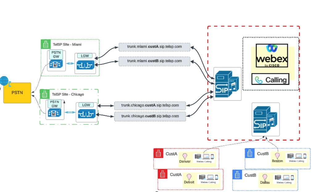
该合作伙伴有两个物理站点,并且这两个站点共享PSTN连接:
-
迈阿密
-
芝加哥
-
-
TelSP代表本协议中提及的两个客户CustA和CustB操作其本地网关。
在本文中,“合作伙伴”一词指的是管理Webex合作伙伴,尤其是本示例中的TelSP。此实体有权访问Webex合作伙伴中心。
| 位置 | CustA | 中层B |
|---|---|---|
|
使用迈阿密网关作为主要PSTN目标的位置 |
丹佛 |
Dallas |
|
使用芝加哥网关作为主要PSTN目标的位置 |
底特律 |
波士顿 |
|
为客户选择的子域 | custa.sip.telsp.com | custb.sip.telsp.com |
期望的场景是使用合作伙伴提供的迈阿密和芝加哥网关为客户提供PSTN发起/终止,如图所示:
将客户位置关联到干线和网关
Webex 允许创建中继并跨多个位置共享中继。创建干线时,将干线与位置关联。
对于CustA,中继详细信息如下:
| 中继名称 | FQDN | 中继定义中的关联位置 |
|---|---|---|
| trunk_miami | trunk.miami.custa.sip.telsp.com | 丹佛 |
| trunk_chicago | trunk.chicago.custa.sip.telsp.com | 底特律 |
此图显示了客户位置与 CustA 的网关和中继的关联:
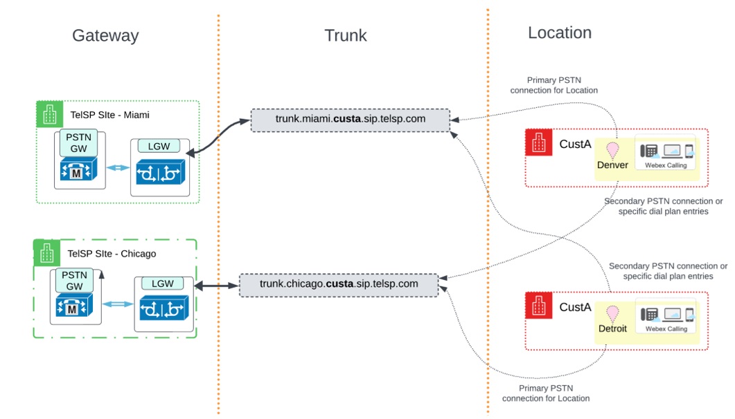
在此部署中,与该位置关联的干线是该位置的主PSTN连接。另一干线用作特定拨号方案条目的辅助PSTN连接或路由。主要和辅助PSTN连接关系的实现是通过路由组概念实现的。有关详细信息,请参阅 bex客户设置 部分。
对于CustB,将创建具有以下干线的类似设置:
| 中继名称 | FQDN | 中继定义中的关联位置 |
|---|---|---|
| trunk_miami | trunk.miami.custb.sip.telsp.com |
Dallas |
| trunk_chicago | trunk.chicago.custb.sip.telsp.com |
波士顿 |
此图显示了客户位置与 CustB 的网关和中继的关联:
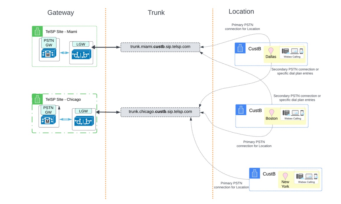
此图显示了第三个位置,即纽约,您可以稍后添加,并将其trunk_chicago 线作为其主要PSTN连接。
配置IP地址的要求
部署共享多个干线的本地网关时,Cisco要求每个干线使用唯一的FQDN。有关详细信息,请参阅 -干线、-路由组、和-dial-plans-for-Webex - 。
使用IP地址和每个干线众所周知的端口是理想的选择。但是,对于希望每个站点每个网关使用一个地址的某些合作伙伴来说,获取公共IPv4地址可能很困难。
因此,请阅读以下重要指示:
-
Cisco没有强制要求每个干线使用IP地址。
-
干线地址可以解析为唯一的IP地址或其他干线之间共享的地址。
-
由于以下原因,Cisco建议每个干线使用唯一的侦听端口:
-
提供客户之间的网络级别隔离
-
会话边界控制器通常会重用临时TCP socket连接,除非存在由IP地址分区的唯一租户或租户的唯一侦听端口所提供的隔离。
-
通过租户隔离每个干线的连接或连接可提供更好的吞吐量,特别是在数据损耗高的网络条件下。因此,一个客户的流量不会影响另一个客户。
-
每个网关的IP地址:干线配置和建议
请参考以下不同模型的示例进行规划:
模型1:每个干线唯一的IP地址
在此模型中,两个网关托管的所有干线解析为唯一的IP地址,每个干线可能使用或不使用相同的端口,但理想情况下使用相同的端口。
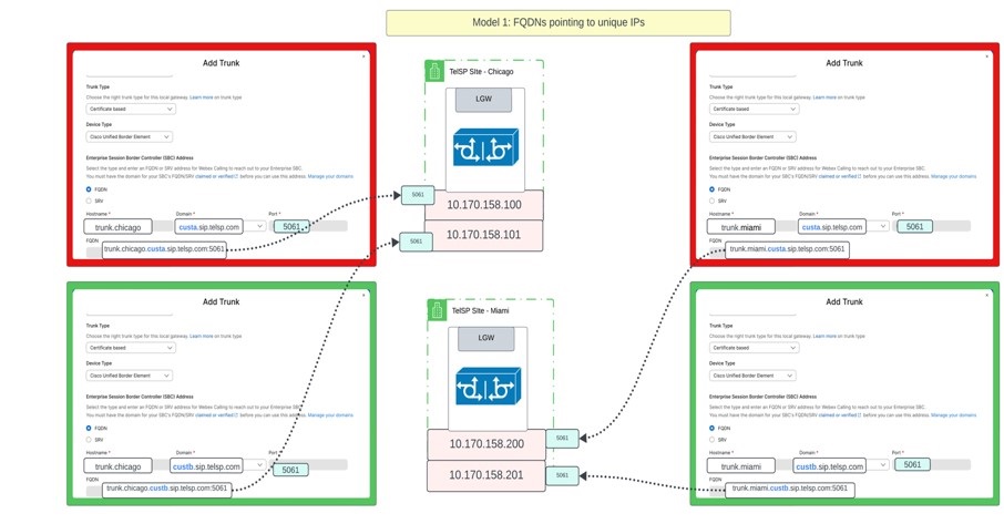
以表格格式表示信息:
| 干线地址(FQDN) | IP 地址 | 端口 |
|---|---|---|
| trunk.miami.custa.sip.telsp.com | 10.170.158.200 | 5061 |
| trunk.miami.custb.sip.telsp.com | 10.170.158.201 | 5061 |
| trunk.chicago.custa.sip.telsp.com | 10.170.158.100 | 5061 |
| trunk.chicago.custb.sip.telsp.com | 10.170.158.101 | 5061 |
在同一模型中,合作伙伴可以使用SRV地址。如果是SRV记录,Webex 仅允许“_sips。_tcp”作为服务和协议组合来发现对等地址。
| 干线地址(SRV) | SRV地址 | 一条记录 | IP 地址 | 端口 |
|---|---|---|---|---|
| trunk.miami.custa.sip.telsp.com | _sips._tcp.trunk.miami.custa.sip.telsp.com | miami.custa.sip.telsp.com | 10.170.158.200 | 5061 |
| trunk.miami.custb.sip.telsp.com | _sips._tcp.trunk.miami.custb.sip.telsp.com | miami.custb.sip.telsp.com | 10.170.158.201 | 5061 |
| trunk.chicago.custa.sip.telsp.com | _sips._tcp.trunk.chicago.custa.sip.telsp.com | chicago.custa.sip.telsp.com | 10.170.158.100 | 5061 |
| trunk.chicago.custb.sip.telsp.com | _sips._tcp.trunk.chicago.custb.sip.telsp.com | chicago.custb.sip.telsp.com | 10.170.158.101 | 5061 |
SRV记录如何解析示例
lookup -type=srv_sips。_tcp。trunk.miami.custa.sip.telsp.com服务器:8.8.8.8地址:8.8.8.8#53非权威答案:_sips。_tcp。trunk.miami.custa.sip.telsp.com = 3600 50,5061 miami.custa.sip.telsp.com 型号2:网关上共享IP,但侦听端口不同
在此模型中,托管在芝加哥本地网关上的所有干线解析到相同的IP地址,而托管在迈阿密本地网关上的所有干线解析到不同的IP。但是,当使用相同的IP时,每个干线都使用控制中心中的FQDN进行配置,并且配置了唯一的端口。
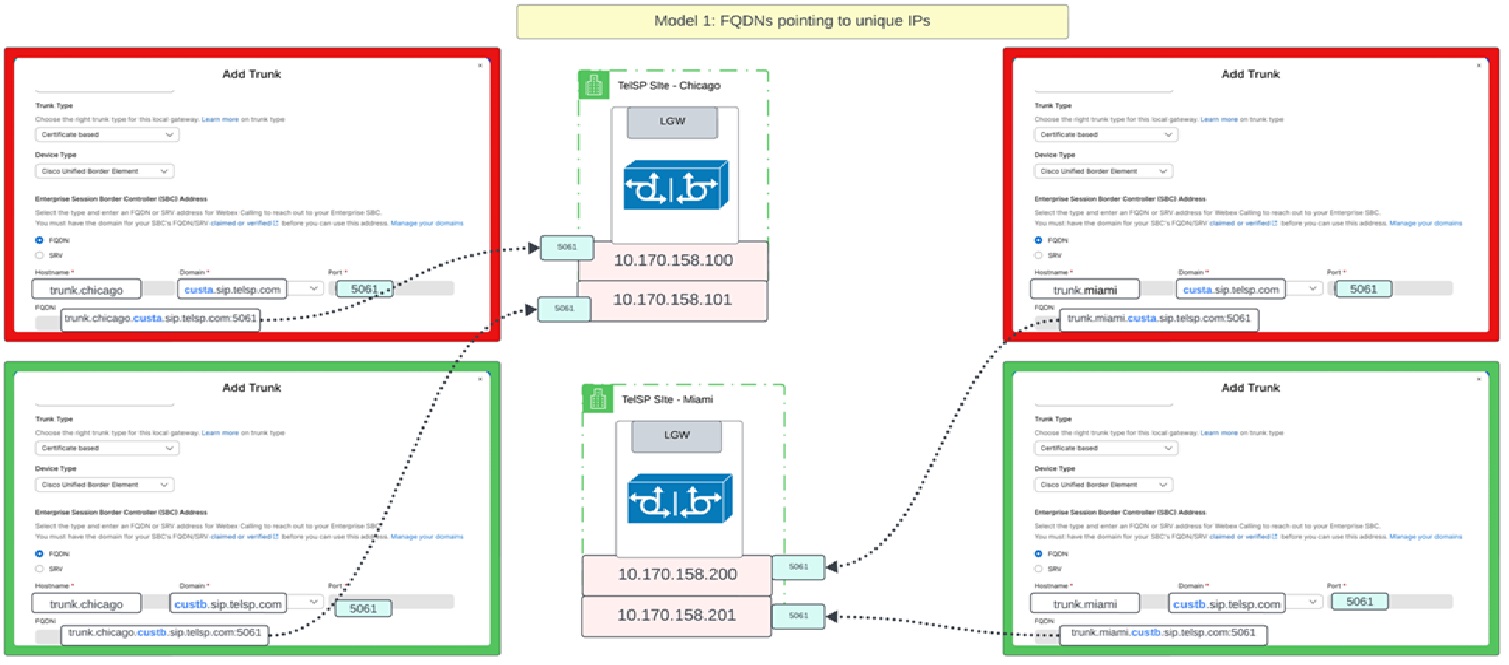
| 中继地址 | IP 地址 | 端口 |
|---|---|---|
| trunk.miami.custa.sip.telsp.com | 10.170.158.200 | 5061 |
| trunk.miami.custb.sip.telsp.com | 10.170.158.200 | 5062 |
| trunk.chicago.custa.sip.telsp.com | 10.170.158.100 | 5061 |
| trunk.chicago.custb.sip.telsp.com | 10.170.158.100 | 5062 |
在同一模型中,合作伙伴使用的是SRV地址。如果是SRV记录,Webex 仅允许“_sips。_tcp”作为服务和协议组合来发现对等地址。
| 干线地址(SRV) | SRV地址 | 一条记录 | IP 地址 | 端口 |
|---|---|---|---|---|
| trunk.miami.custa.sip.telsp.com | _sips._tcp.trunk.miami.custa.sip.telsp.com | miami.sip.telsp.com | 10.170.158.200 | 5061 |
| trunk.miami.custb.sip.telsp.com | _sips._tcp.trunk.miami.custb.sip.telsp.com | miami.sip.telsp.com | 10.170.158.200 | 5062 |
| trunk.chicago.custa.sip.telsp.com | _sips._tcp.trunk.chicago.custa.sip.telsp.com | chicago.sip.telsp.com | 10.170.158.100 | 5061 |
| trunk.chicago.custb.sip.telsp.com | _sips._tcp.trunk.chicago.custb.sip.telsp.com | chicago.sip.telsp.com | 10.170.158.100 | 5062 |
SRV记录如何解析的另一个示例如下。在本例中,每个IP地址存在1 A条记录。但是,每个地址的端口都是唯一的,通过将SRV地址链接到正确端口的特定DNS配置表示。
lookup -type=srv_sips。_tcp。trunk.miami.custa.sip.telsp.com服务器:8.8.8.8地址:8.8.8.8#53非权威答案:_sips。_tcptrunk.miami.custa.sip.telsp.com = 3600 50,5061 miami.sip.telsp.com nslookup -type=srv _sips。_tcptrunk.miami.custb.sip.telsp.com服务器:8.8.8.8地址:8.8.8.8#53非权威答案:_sips。_tcp.trunk.miami.custb.sip.telsp.com = 3600 50,5062 miami.sip.telsp.com设置域服务器并生成证书
该合作伙伴拥有telsp.com及其子域。因此,DNS服务器和获取经批准的证书颁发机构签名的证书的权限属于合作伙伴。
使用FQDN作为干线地址时,设置签名证书,将公用名(CN)或主题号码备用号码(SAN)设置为干线的FQDN。
| 合作伙伴托管网关 | 客户 | 干线地址 | 证书CN/SAN |
|---|---|---|---|
| 迈阿密 | CustA | trunk.miami.custa.sip.telsp.com | trunk.miami.custa.sip.telsp.com |
| 中层B | trunk.miami.custb.sip.telsp.com | trunk.miami.custb.sip.telsp.com | |
| 芝加哥 | CustA | trunk.chicago.custa.sip.telsp.com | trunk.chicago.custa.sip.telsp.com |
| 中层B | trunk.chicago.custa.sip.telsp.com | trunk.chicago.custa.sip.telsp.com |
使用以下方法之一生成证书中的FQDN:
-
选择其中一个FQDN作为通用名称(CN),其余选择为受验者号码备用号码(SAN)。
-
将顶级域(sip.telsp.com)放置为CN,将所有FQDN放置为SAN。
将来,您可以根据此配置分配的顶层域来验证证书。
当使用SRV作为干线地址时,使用CN或SAN设置签名证书到SRV地址的主机部分。SRV地址解析为的A记录或CNAME不是必需的。
| 合作伙伴托管网关 | 客户 | 干线地址 | SRV地址 | 证书CN/SAN |
|---|---|---|---|---|
| 迈阿密 | CustA | trunk.miami.custa.sip.telsp.com | _sips._tcp.trunk.miami.custa.sip.telsp.com | trunk.miami.custa.sip.telsp.com |
| 中层B | trunk.miami.custb.sip.telsp.com | _sips._tcp.trunk.miami.custb.sip.telsp.com | trunk.miami.custb.sip.telsp.com | |
| 芝加哥 | CustA | trunk.chicago.custa.sip.telsp.com | _sips._tcp.trunk.chicago.custa.sip.telsp.com | trunk.chicago.custa.sip.telsp.com |
| 中层B | trunk.chicago.custb.sip.telsp.com | _sips._tcp.trunk.chicago.custb.sip.telsp.com | trunk.chicago.custb.sip.telsp.com |
设置网关
使用这些资源设置本地网关。
要设置Cisco CUBE,请执行以下程序:为 Webex Calling 配置 Cisco IOS-XE 上的本地网关
您可以设置获得批准的第三方SBC,请参阅:本地网关入门
根据以下准则设置合作伙伴托管网关:本地网关入门
根据SBC设备的相关说明设置每个干线。有关Cisco CUBE说明,请参阅:为 Webex Calling 配置 Cisco IOS-XE 上的本地网关
根据图像为干线的传入和传出流量设置语音类、拨号对等方和拨号对等方组: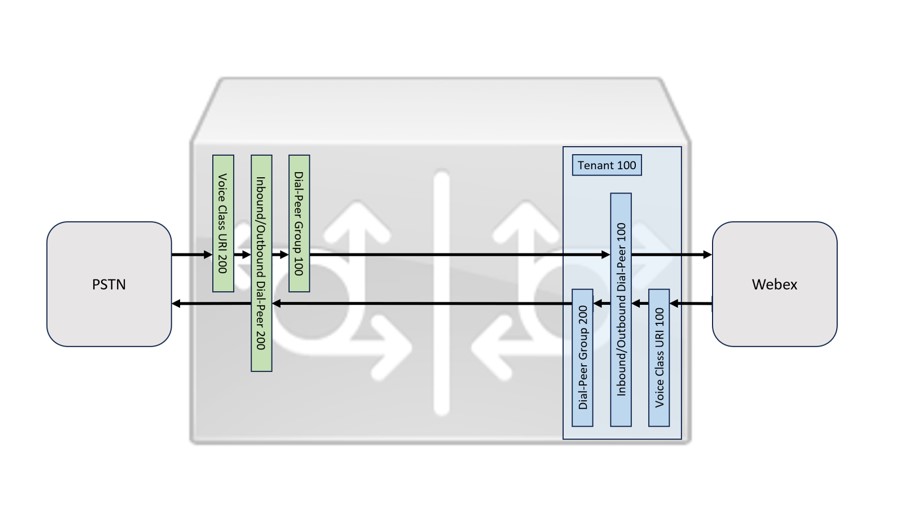
在Control Hub中配置网关干线
从Partner Hub,您可以启动CustA或CustB的Control Hub并配置网关。此程序用于为每个客户配置:
- 创建中继-在呼叫/呼叫路由/中继下为每个合作伙伴共享网关添加中继。要设置中继,请参阅 Webex Calling 的中继、路由组和拨号方案
-
添加域并验证-添加并验证以下域,用于在管理/组织设置/域下创建中继。
CustA 中层B sip.telsp.com sip.telsp.com 添加域时,会生成令牌并将其放置在合作伙伴DNS服务器中的域的TXT记录中。此记录允许Control Hub验证该域是否为合作伙伴所有。有关详细信息,请参阅管理您的域
由于公共域用于对每个客户进行验证。但是,由于此验证发生在客户组织级别,请确保生成不同的令牌并用于每个客户组织的验证。由于单个域在客户组织中使用,任何一个组织都无法申领域所有权。 - 使用FQDN设置SBC地址-
迈阿密网关:
参数 CustA 中层B 位置 丹佛 波士顿 中继名称 trunk_miami trunk_miami 中继类型 基于证书 基于证书 设备类型 例如Cisco Unified Border Element(或其他支持的设备) 例如Cisco Unified Border Element(或其他支持的设备) SBC地址类型 FQDN FQDN 主机名 干线。miami.custa 中继。miami.custb 域 sip.telsp.com sip.telsp.com 端口 5061 5062 FQDN trunk.miami.custa.sip.telsp.com:5061 trunk.miami.custb.sip.telsp.com:5062 并发呼叫数最大值(250-6500) 500 500 对于芝加哥网关:
参数 CustA 中层B 位置 底特律 Dallas 中继名称 trunk_chicago trunk_chicago 中继类型 基于证书 基于证书 设备类型 例如Cisco Unified Border Element(或其他支持的设备) 例如Cisco Unified Border Element(或其他支持的设备) SBC地址类型 FQDN FQDN 主机名 干线。chicago.custa 干线。chicago.custb 域 sip.telsp.com sip.telsp.com 端口 5061 5062 FQDN trunk.chicago.custa.sip.telsp.com:5061 trunk.chicago.custb.sip.telsp.com:5062 并发呼叫数最大值(250-6500) 500 500 -
(可选)没有跨客户中继的唯一名称,相同名称可帮助跟踪中继。
-
某些SBC允许配置相同的端口,但此配置可能会影响容量。因此,请使用不同的端口。
-
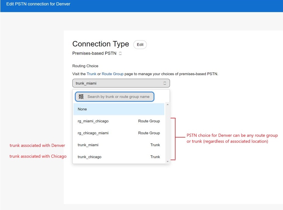
- 使用干线-为干线选择任意位置,原因如下:
-
任何位置都可以使用PSTN连接中的中继。
-
您可以通过路由组访问中继。
-
任何拨号方案都可以使用中继。
-
请参阅具有关联位置的中继定义:
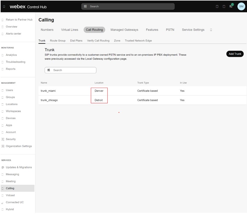
您可以使用这些中继创建路由组。在图像中,路由组rg_miami_chicago 定义了将呼叫路由到trunk_miami 线作为主选项和trunk_chicago 线作为辅助选项。
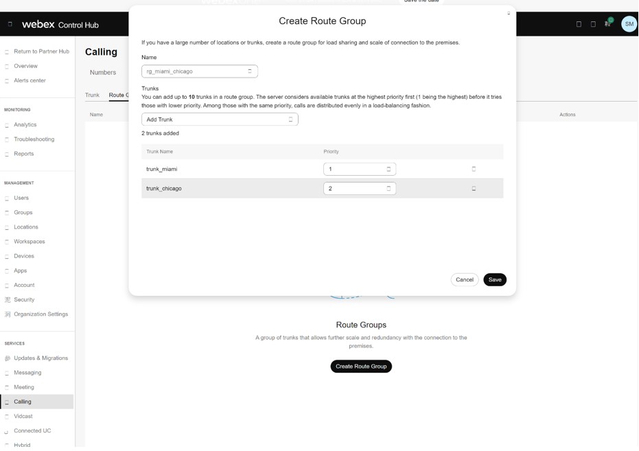
您可以定义第二个路由组rg_chicago_miami ,将呼叫路由到trunk_chicago 线作为主选项,trunk_miami 线作为辅助选项。
-
定义的中继和路由组现可在每个位置的 Connection PSTN选项中使用。在图中,请查看丹佛的位置。
-
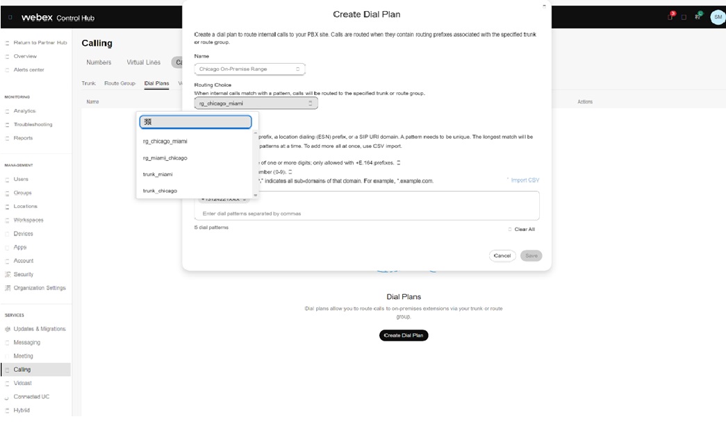
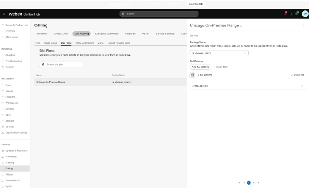
您可以在拨号方案定义中使用中继和路由组。例如,将客户在芝加哥的本地部署号码范围拆分为图中的rg_chicago_miami 由组(针对所有位置):
