- Home
- /
- Article

Thanks for your feedback.

Configuring a Partner Hosted Gateway
 In this article
 Feedback?
These instructions are for Partners intending to host a gateway. Read through to understand the best practices and recommendations.
Webex Calling allows a customer to configure a local gateway trunk to send and receive a PSTN call. If a partner hosts trunks from different customers, it’s recommended to set up a shared gateway for these trunks.
This document outlines a high-level scheme for implementing a partner hosted gateway and focuses on certificate-based trunking. The registration-based model is a simple model to use for a partner hosted gateway that provides a solution for smaller capacity trunks. This solution possesses inherent technical limitations for high-capacity trunks specifically for TCP based traffic and connection sharing model. The main reason for creating certificate-based trunking is to solve the scale limitations of the registration-based model.
The procedure for trunk creation and gateway configuration is similar to the customer hosted local gateway. For details, see: Get started with Local Gateway
Considerations for deployment
Lets consider a hypothetical Webex partner named TelSP to illustrate the different models of deployments that the partner can adopt.
Here are the high-level specifications & requirements of TelSP:
-
The partner plans on using
sip.telsp.comas the top-level domain that is shared across all the customers they manage. -
The partner owns
sip.telsp.comand can administer the DNS infrastructure and Certificate authorities, manage DNS addresses, and sign certificates for this domain and its sub domains. -
The partner can deploy two distinct session border controllers (physical or virtual) as Local Gateways for shared PSTN access among end customers.
-
The partner has two physical sites, and both these sites share PSTN connectivity:
-
Miami
-
Chicago
-
-
TelSP operates their local gateways on behalf of the two customers CustA and CustB as they are referred to from herewith.
In this article, the term partner refers to the managing Webex partner, specifically TelSP in this example. This entity has access to Webex partner hub.
| Location | CustA | Cust B |
|---|---|---|
|
Locations using Miami Gateway as primary PSTN destination |
Denver |
Dallas |
|
Locations using Chicago gateway as primary PSTN destination |
Detroit |
Boston |
|
Subdomain chosen for a customer | custa.sip.telsp.com | custb.sip.telsp.com |
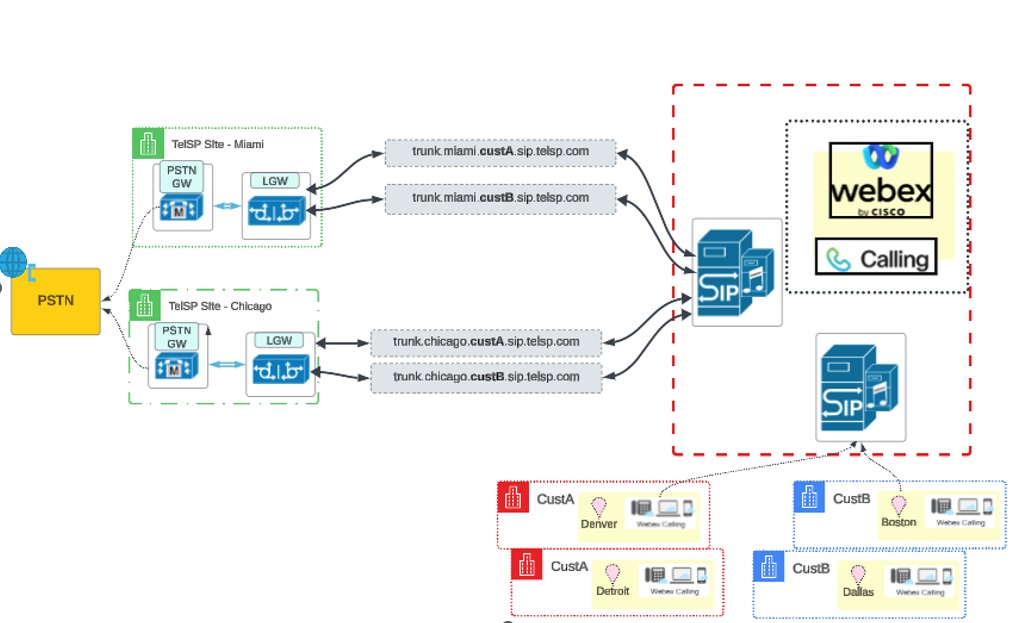
The desired scenario is to have PSTN origination/termination for both customers using the Miami and Chicago gateways supplied by the partner, as shown in the illustration:
Associating customer location to trunk and gateway
Webex Calling allows creation of trunks and sharing a trunk across multiple locations. When creating the trunk, associate the trunk with a location.
For CustA, the trunk details are as follows:
| Trunk name | FQDN | Associated location in trunk definition |
|---|---|---|
| trunk_miami | trunk.miami.custa.sip.telsp.com | Denver |
| trunk_chicago | trunk.chicago.custa.sip.telsp.com | Detroit |
The illustration shows the association of the customer location to Gateway and Trunk for CustA:
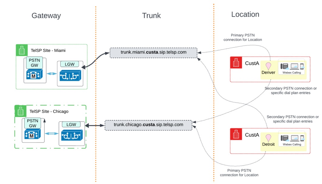
In this deployment, the trunk associated with the location is the primary PSTN connection for that location. The other trunk is used as a secondary PSTN connection or route for specific dial plan entries. The implementation of the primary and secondary PSTN connection relationship is through a Route Group concept. See the Webex Customer Setup section for details.
For CustB, a similar setup with the following trunks is created:
| Trunk name | FQDN | Associated location in trunk definition |
|---|---|---|
| trunk_miami |
trunk.miami.custb.sip.telsp.com
|
Dallas |
| trunk_chicago |
trunk.chicago.custb.sip.telsp.com
|
Boston |
The illustration shows the association of the customer location to Gateway and Trunk for CustB:
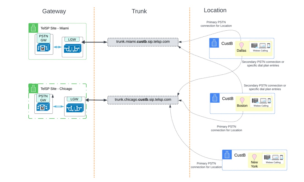
The illustration shows a third location namely New York, which you can add later and point to the trunk_chicago trunk as its primary PSTN connection.
Requirements to configure IP address
When deploying a local gateway that shares multiple trunks, Cisco MANDATES using a unique FQDN per trunk. See Configure-trunks,-route-groups,-and-dial-plans-for-Webex-Calling for details.
Using an IP address and a well-known port per trunk is an ideal choice. However, procuring a public IPv4 address can be challenging to some partners who wish to use one address per gateway per site.
Therefore read these important pointers:
-
Cisco doesn’t mandate an IP address per trunk.
-
A trunk address can resolve to a unique IP address or to the address shared between another trunk.
-
Cisco recommends to configure each trunk connection with a unique IP address and port combination on the Local Gateway for the following reasons:
-
Maintaining separate TCP connection links per trunk supports the maximum concurrent call capacity per trunk. Sharing IP address and port combinations across trunks can negatively impact call capacity.
-
Provides network level isolation between customers
-
It’s typical of Session border controllers to reuse the ephemeral TCP socket connection unless there’s isolation provided as a unique tenant partitioned by an IP address or a unique listen port for the tenant.
-
Connection or connections per trunk through tenant isolation provides better throughput specifically in network conditions with high data loss. Therefore traffic from one customer doesn’t impact the other.
-
IP Address per gateway: Trunk configuration and recommendations
Refer to these examples of different models for planning:
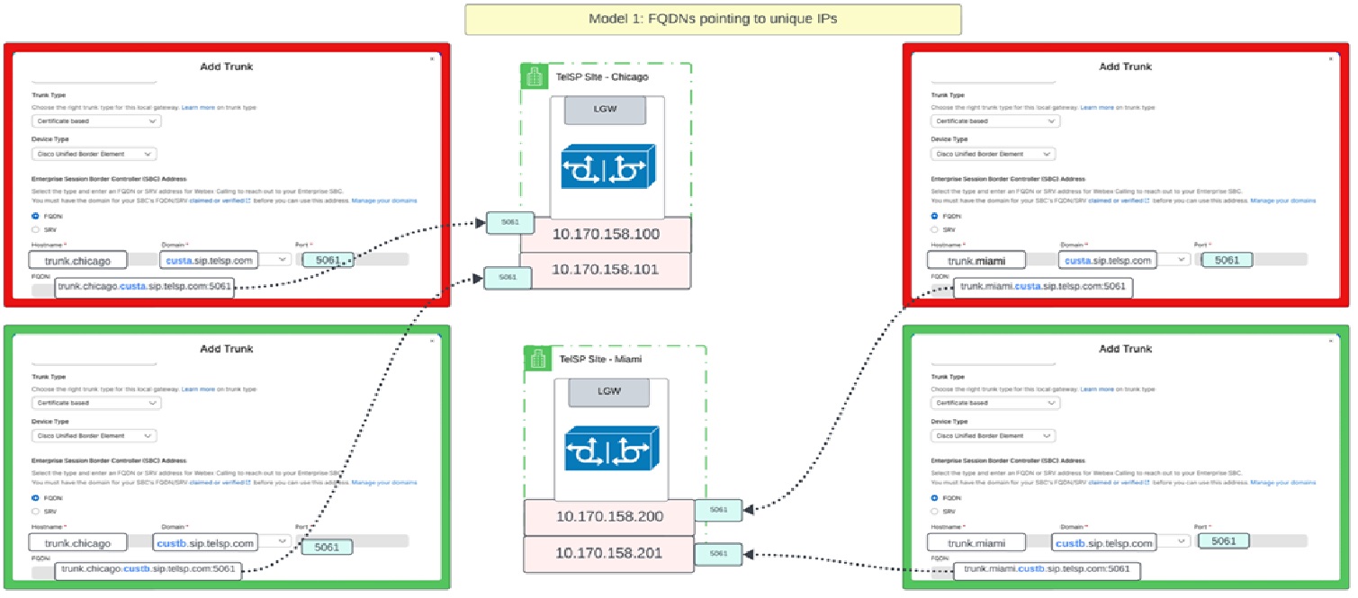
Model 1: Unique IP address per trunk
In this model, all trunks hosted by both gateways resolve to a unique IP address and each of these trunks may or may not use the same port but ideally the same port.
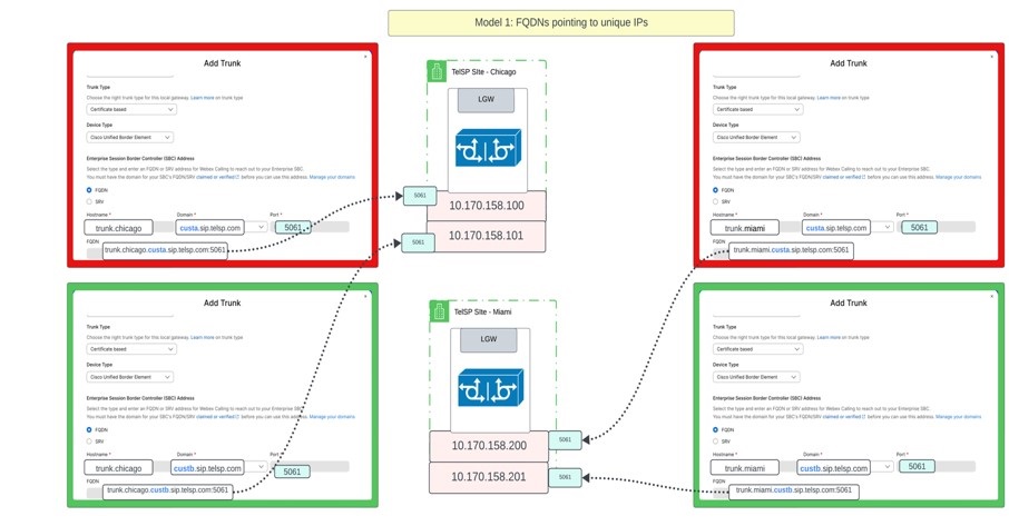
Representing the information in a tabular format:
| Trunk address (FQDN) | IP address | Port |
|---|---|---|
| trunk.miami.custa.sip.telsp.com | 10.170.158.200 | 5061 |
| trunk.miami.custb.sip.telsp.com | 10.170.158.201 | 5061 |
| trunk.chicago.custa.sip.telsp.com | 10.170.158.100 | 5061 |
| trunk.chicago.custb.sip.telsp.com | 10.170.158.101 | 5061 |
In this same model, the partner can use an SRV address. Webex Calling only allows “_sips._tcp” as the service and protocol combination to discover the peer address if it’s an SRV record.
| Trunk address (SRV) | SRV Address | A Record | IP Address | Port |
|---|---|---|---|---|
| trunk.miami.custa.sip.telsp.com | _sips._tcp.trunk.miami.custa.sip.telsp.com | miami.custa.sip.telsp.com | 10.170.158.200 | 5061 |
| trunk.miami.custb.sip.telsp.com | _sips._tcp.trunk.miami.custb.sip.telsp.com | miami.custb.sip.telsp.com | 10.170.158.201 | 5061 |
| trunk.chicago.custa.sip.telsp.com | _sips._tcp.trunk.chicago.custa.sip.telsp.com | chicago.custa.sip.telsp.com | 10.170.158.100 | 5061 |
| trunk.chicago.custb.sip.telsp.com | _sips._tcp.trunk.chicago.custb.sip.telsp.com | chicago.custb.sip.telsp.com | 10.170.158.101 | 5061 |
A sample of how an SRV record resolves
nslookup -type=srv _sips._tcp.trunk.miami.custa.sip.telsp.com
Server:		8.8.8.8
Address:	8.8.8.8#53

Non-authoritative answer:
_sips._tcp.trunk.miami.custa.sip.telsp.com = 3600 50 5061 miami.custa.sip.telsp.com
Model 2: Shared IP on a gateway but different listen ports
In this model, all trunks hosted on the Chicago local gateway resolves to the same IP address and all trunks hosted on the Miami local gateway resolves to a different IP. However, when using the same IP, each trunk is configured using an FQDN in the control hub and is configured with a unique port.
| Trunk address | IP Address | Port |
|---|---|---|
| trunk.miami.custa.sip.telsp.com | 10.170.158.200 | 5061 |
| trunk.miami.custb.sip.telsp.com | 10.170.158.200 | 5062 |
| trunk.chicago.custa.sip.telsp.com | 10.170.158.100 | 5061 |
| trunk.chicago.custb.sip.telsp.com | 10.170.158.100 | 5062 |
In this same model, the partner is using an SRV address. Webex Calling only allows “_sips._tcp” as the service and protocol combination to discover the peer address if it’s an SRV record.
| Trunk address (SRV) | SRV Address | A Record | IP Address | Port |
|---|---|---|---|---|
| trunk.miami.custa.sip.telsp.com | _sips._tcp.trunk.miami.custa.sip.telsp.com | miami.sip.telsp.com | 10.170.158.200 | 5061 |
| trunk.miami.custb.sip.telsp.com | _sips._tcp.trunk.miami.custb.sip.telsp.com | miami.sip.telsp.com | 10.170.158.200 | 5062 |
| trunk.chicago.custa.sip.telsp.com | _sips._tcp.trunk.chicago.custa.sip.telsp.com | chicago.sip.telsp.com | 10.170.158.100 | 5061 |
| trunk.chicago.custb.sip.telsp.com | _sips._tcp.trunk.chicago.custb.sip.telsp.com | chicago.sip.telsp.com | 10.170.158.100 | 5062 |
A another sample of how an SRV record resolves is as follows. In this example, there exists 1 A record per IP address. However, the port is unique per address and is represented through a specific DNS configuration linking an SRV address to the right port.
nslookup -type=srv _sips._tcp.trunk.miami.custa.sip.telsp.com
Server:		8.8.8.8
Address:	8.8.8.8#53

Non-authoritative answer:
_sips._tcp.trunk.miami.custa.sip.telsp.com = 3600 50 5061 miami.sip.telsp.com

nslookup -type=srv _sips._tcp.trunk.miami.custb.sip.telsp.com
Server:		8.8.8.8
Address:	8.8.8.8#53

Non-authoritative answer:
_sips._tcp.trunk.miami.custb.sip.telsp.com = 3600 50 5062 miami.sip.telsp.com
Set up a domain server and generate the certificate
The partner owns telsp.com and its subdomains. Therefore, the DNS server and the authority to get certificates signed by an approved Certificate authority lies with the partner.
-
Cisco Webex expects the partner to publish the FQDN or SRV address including A Records in the public domain.
-
Cisco Webex expects the partner to use one of the certificate authorities listed in as published in this document.
When using an FQDN as the trunk address, set up the signed certificates with the Common Name (CN) or Subject Number Alternative Number (SAN) set to the FQDNs for the trunks.
| Partner Hosted Gateway | Customer | Trunk Address | Certificate CN/SAN |
|---|---|---|---|
| Miami | CustA | trunk.miami.custa.sip.telsp.com | trunk.miami.custa.sip.telsp.com |
| CustB | trunk.miami.custb.sip.telsp.com | trunk.miami.custb.sip.telsp.com | |
| Chicago | CustA | trunk.chicago.custa.sip.telsp.com | trunk.chicago.custa.sip.telsp.com |
| CustB | trunk.chicago.custa.sip.telsp.com | trunk.chicago.custa.sip.telsp.com |
Use one of these methods to generate the FQDNs in the certificate:
-
Choose one of the FQDNs as the Common Name (CN) and the rest as Subject Number Alternative Number (SAN).
-
Place the top-level domain (sip.telsp.com) as the CN and all the FQDNs as SANs.
In the future, you can validate the certificate based on the top-level domain that this configuration appropriates.
When using an SRV as the trunk address, set up signed certificates with the CN or SAN to the host portion of the SRV address. The A Record or CNAME that the SRV address resolves to isn’t required.
| Partner Hosted Gateway | Customer | Trunk Address | SRV address | Certificate CN/SAN |
|---|---|---|---|---|
| Miami | CustA | trunk.miami.custa.sip.telsp.com | _sips._tcp.trunk.miami.custa.sip.telsp.com | trunk.miami.custa.sip.telsp.com |
| CustB | trunk.miami.custb.sip.telsp.com | _sips._tcp.trunk.miami.custb.sip.telsp.com | trunk.miami.custb.sip.telsp.com | |
| Chicago | CustA | trunk.chicago.custa.sip.telsp.com | _sips._tcp.trunk.chicago.custa.sip.telsp.com | trunk.chicago.custa.sip.telsp.com |
| CustB | trunk.chicago.custb.sip.telsp.com | _sips._tcp.trunk.chicago.custb.sip.telsp.com | trunk.chicago.custb.sip.telsp.com |
Set up the Gateway
Use these resources to set up a local gateway.
To set up Cisco CUBE, use this procedure: Configure Local Gateway on Cisco IOS XE for Webex Calling
You can set up approved third-party SBCs, see: Get started with Local Gateway
Set up the partner hosted gateway in accordance with these guidelines: Get started with Local Gateway
Set each trunk according to the relevant instructions for the SBC device. For the Cisco CUBE instructions, see: Configure Local Gateway on Cisco IOS XE for Webex Calling
Set up voice classes, dial peers, and dial peer groups for incoming and outgoing traffic for the trunk as per the image: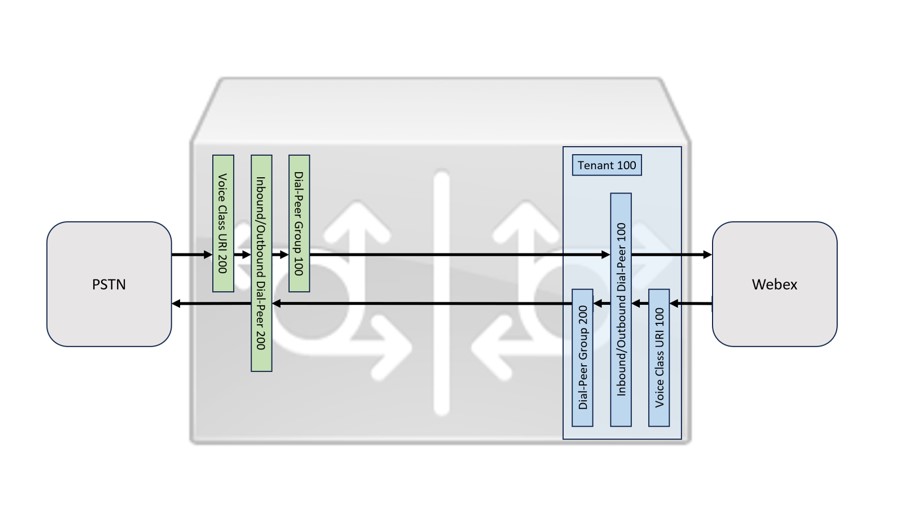
Configure gateway trunks in the Control Hub
From the Partner Hub, you can launch the Control Hub for either CustA or CustB and configure the gateway. Use this procedure to configure for each customer:
- Create the trunk—Add a trunk under Calling/Call Routing/Trunk for each partner shared gateway. To set up a trunk, see Configure trunks, route groups, and dial plans for Webex Calling
-
Add a domain and verify—Add and verify the following domain that is used to create a trunk under Management/Organization Settings/Domains.
CustA CustB sip.telsp.com sip.telsp.com On adding a domain, a token is generated and placed in the TXT record for the domain in the partner’s DNS server. This record allows Control Hub to verify that the domain is owned by the partner. For details, see Manage your domains
Since The common domain is used for verification on each customer. However, since this verification happens at the customer organization level, ensure that a different token is generated and used for verification on each customer organization. Because a single domain is used across customer organizations, any one organization cannot claim the domain ownership. - Set up SBC address with FQDN—
For the Miami gateway:
Parameter CustA CustB Location Denver Boston Trunk Name trunk_miami trunk_miami Trunk Type Certificate based Certificate based Device Type e.g. Cisco Unified Border Element (or another supported device) e.g. Cisco Unified Border Element (or another supported device) SBC Address type FQDN FQDN Hostname trunk.miami.custa trunk.miami.custb Domain sip.telsp.com sip.telsp.com Port 5061 5062 FQDN trunk.miami.custa.sip.telsp.com:5061 trunk.miami.custb.sip.telsp.com:5062 Maximum number of concurrent calls (250-6500) 500 500 For the Chicago gateway:
Parameter CustA CustB Location Detroit Dallas Trunk Name trunk_chicago trunk_chicago Trunk Type Certificate based Certificate based Device Type e.g. Cisco Unified Border Element (or another supported device) e.g. Cisco Unified Border Element (or another supported device) SBC Address type FQDN FQDN Hostname trunk.chicago.custa trunk.chicago.custb Domain sip.telsp.com sip.telsp.com Port 5061 5062 FQDN trunk.chicago.custa.sip.telsp.com:5061 trunk.chicago.custb.sip.telsp.com:5062 Maximum number of concurrent calls (250-6500) 500 500 -
(Optional) Don’t have a unique name for the Trunk across customers and the same name can help in tracking the trunk.
-
Certain SBCs allow configuring the same port but this configuration can impact the capacity. Therefore, use different ports.
-
- Using Trunks—choose any arbitrary location for the trunk, due to the following:
-
Any location can use the trunk in a PSTN connection.
-
You can access the trunk through a route group.
-
Any dial plan can use the trunk.
-
See the trunk definitions with the associated locations:
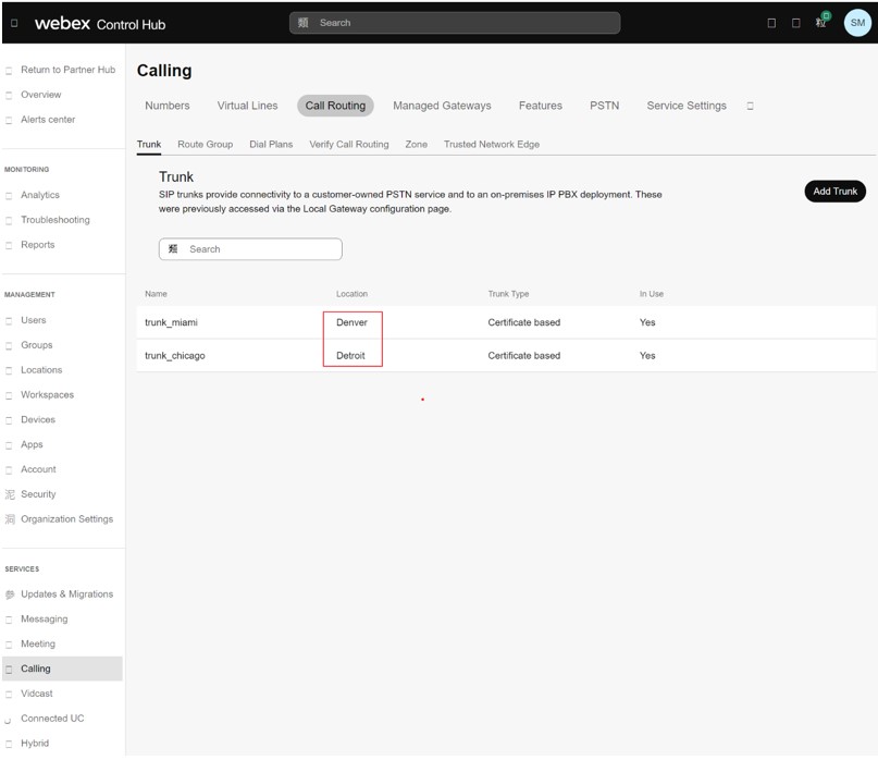
You can use these trunks to create route groups. In the image, a route group rg_miami_chicago is defined which routes calls to the trunk_miami trunk as the primary option and to the trunk_chicago trunk as a secondary option.
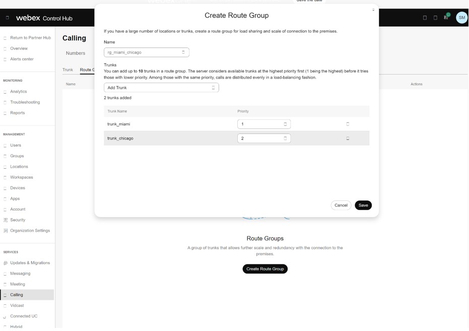
You can define a second route group rg_chicago_miami which routes calls to the trunk_chicago trunk as the primary option and to the trunk_miami trunk as a secondary option.
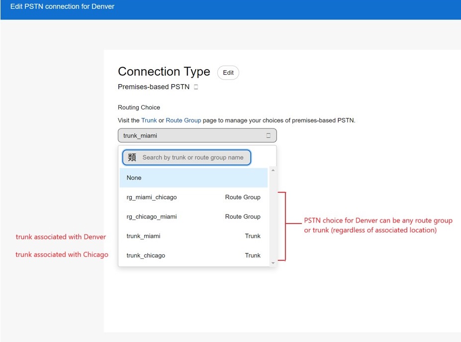
-
The trunks and route groups defined are now available in the Calling Connection PSTN option for each location. In the image, see the Denver location.
-
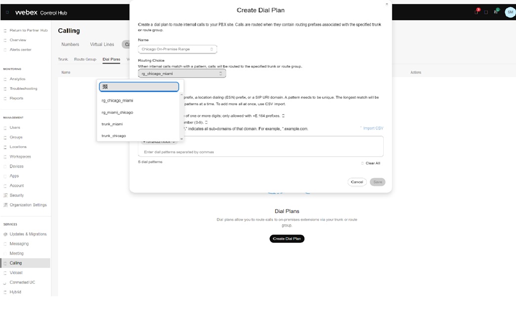
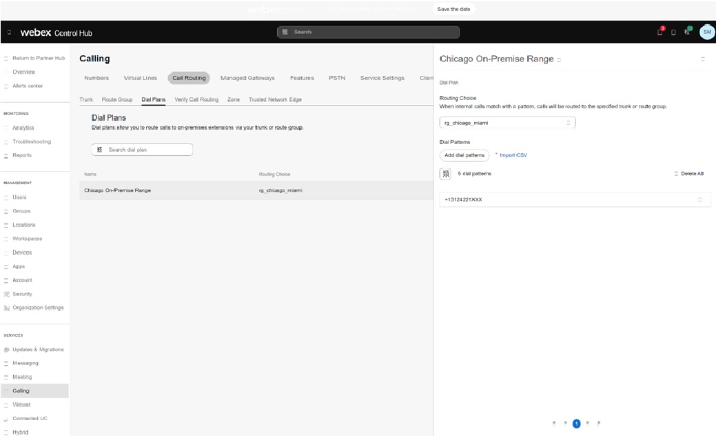
You can use the trunks and route groups in the dial plan definition. For example, an on-premise number range in Chicago for the customer are split out to terminate to the rg_chicago_miami route group (for all locations) in the image: