- Home
- /
- Article

Thanks for your feedback.

Site survivability for Webex Calling
 In this article
 Feedback?
Site Survivability ensures your business remains reachable even if the connection to Webex is lost. It uses a local network gateway to provide fallback calling services to on-site endpoints during network outages.
Deployment considerations
By default, Webex Calling endpoints operate in Active mode, connecting to the Webex cloud for SIP registration and call control. If the network connection to Webex is lost, endpoints automatically switch to Survivability mode and register with the local Survivability Gateway. In this mode, the gateway provides basic backup calling services. Once the network connection to Webex is restored, call control and registrations switch back to the Webex cloud.
The following calls are supported in Survivability mode:
-
Internal calling (intrasite) between supported Webex Calling endpoints
-
External calling (incoming and outgoing) using a local PSTN circuit or SIP trunk to external numbers and E911 providers
To use this feature, you must configure a Cisco IOS XE router in the local network as a Survivability Gateway. The Survivability Gateway syncs calling information daily from the Webex cloud for endpoints at that location. If the endpoints switch to Survivability mode, the gateway can use this information to take over SIP registrations and provide basic calling services.
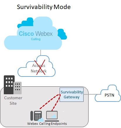
Single location set up
The following image shows a network failure scenario where the connection to Webex is broken and endpoints at the Webex site are operating in Survivability mode. In the image, the Survivability Gateway routes an internal call between two on-site endpoints without requiring a connection to Webex. In this case, the Survivability Gateway is configured with a local PSTN connection. As a result, on-site endpoints in Survivability mode can use the PSTN for incoming and outgoing calls to external numbers and E911 providers.
Multi location set up
The following image shows a network failure scenario where the connection to Webex is broken and endpoints located in different locations are operating in Survivability mode. There are multiple smaller locations within the LAN network that are mapped to a single Survivability gateway. This deployment optimizes gateway resource utilization while preserving location-specific configurations for call routing.
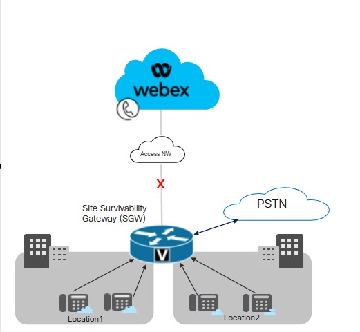
Cisco recommends maintaining a latency threshold of 50 milliseconds for connectivity between Survivability Gateway and endpoints across locations within a LAN.
Key conditions for Site Survivability
The following conditions apply to the Survivability Gateway:
-
The Webex cloud includes the Survivability Gateway IP address, hostname, and port in the device configuration file. As a result, endpoints are able to reach out to the Survivability Gateway for registration if the connection to Webex breaks.
-
The daily call data sync between the Webex cloud and the Survivability Gateway includes authentication information for registered users. As a result, endpoints can maintain secure registrations, even while operating in Survivability mode. The sync also includes routing information for those users.
-
The Survivability Gateway can route internal calls automatically using the routing information that Webex provides. Add a PSTN trunk configuration to the Survivability Gateway to provide external calling.
-
Each site that deploys Site Survivability requires a Survivability Gateway within the local network.
-
Registrations and call control both revert to the Webex cloud once the Webex network connection resumes for at least 30 seconds.
Colocation with Unified SRST
The Survivability Gateway supports the colocation of a Webex Survivability configuration and a Unified SRST configuration on the same gateway. The gateway can support survivability for both Webex Calling endpoints and for endpoints that register to Unified Communications Manager. To configure colocation:
-
Configure Unified SRST support for endpoints that register to Unified Communications Manager. For the configuration, see Cisco Unified SRST Administration Guide.
-
On the same gateway, follow the Site Survivability Configration Task Flow in this article to configure the gateway with Site Survivability for Webex Calling endpoints.
Call routing considerations for colocation
Consider the following when configuring call routing for colocation scenarios:
-
The Survivability Gateway routes internal calls automatically provided that both endpoints in the call are registered to the Survivability Gateway. Internal calls are automatically routed between any registered clients (SRST or Webex Calling).
-
It's possible to have a situation where the connection to one call control system goes down while the connection to the other call control system remains up. As a result, one set of endpoints registers to the Survivability Gateway while another set of endpoints at the same site registers to primary call control. In this case, you may need to route calls between the two sets of endpoints to a SIP trunk or PSTN circuit.
-
External calls and E911 calls can be routed to a SIP trunk or PSTN circuit.
Supported features and components
The following table provides information on supported features.
| Feature | MPP devices and Webex App | VG4xx ATA |
|---|---|---|
|
Intrasite Extension Calling |
Supported automatically with no specific routing configuration required on the Survivability Gateway. |
Supported automatically with no specific routing configuration required on the Survivability Gateway. Alternate numbers aren’t supported. |
|
Intersite and PSTN Calling (Inbound and Outbound) |
PSTN Calling based on telco circuit or SIP trunk. |
PSTN Calling based on telco circuit or SIP trunk. |
|
E911 Call Handling |
E911 Calling requires a PSTN circuit or SIP trunk. Outbound calls use a specific registered Emergency Location Identification Number (ELIN) for a defined Emergency Response Location (ERL). If the emergency operator returns a disconnected call, the Survivability Gateway directs the call to the last device that called the emergency number. |
E911 Calling requires a PSTN circuit or SIP trunk. Outbound calls use a specific registered Emergency Location Identification Number (ELIN) for a defined Emergency Response Location (ERL). If the emergency operator returns a disconnected call, the Survivability Gateway directs the call to the last device that called the emergency number. |
|
Call Hold and Resume |
Supported If you're using Music on Hold (MOH), provision the Survivability Gateway manually with a MOH file. |
VG4xx ATA analog lines can’t put calls on hold or resume. This feature is supported only when an incoming call is received on VG4xx ATA. |
|
Attended Call Transfer |
Supported |
This feature is supported only when an incoming call is received on VG4xx ATA. |
|
Blind Call Transfer |
Supported |
This feature is supported only when an incoming call is received on VG4xx ATA. |
|
Inbound Caller ID (Name) |
Supported |
Supported |
|
Inbound Caller ID (Name & Number) |
Supported |
Supported |
|
Point-to-point Video Call |
Supported |
Not supported |
|
Three-way Calling |
Not supported |
Not supported |
|
Shared Lines |
Supported |
Supported |
|
Virtual Lines |
Supported |
Not supported |
|
Call Forward |
Supported for Call forward All, No Answer and busy. |
Supported |
|
Hunt Group |
Supported for the following: Sequential, Parallel, Peer, and Longest-idle. |
Supported |
|
Auto Attendant |
Supported for dial by extension |
Supported |
On configuring the feature, Site Survivability is available for the following supported endpoints.
| Type | Models | Minimum Version |
|---|---|---|
| Cisco IP Phone with Multiplatform (MPP) Firmware |
6821, 6841, 6851, 6861, 6861 Wi-Fi, 6871 7811, 7821, 7841, 7861 8811, 8841, 8851, 8861 8845 (audio only), 8865 (audio only), 8875(video) 9800 For more information on supported Cisco IP Phones with Multiplatform (MPP) Firmware, see: |
12.0(1) For 8875 phones - Phone OS 3.2 and later versions For 9800 series- PhoneOS 3.2(1) |
|
Cisco IP Conference Phone |
7832, 8832 |
12.0(1) |
|
Cisco Webex App |
Windows, Mac |
43.2 |
|
Analog Endpoints |
VG400 ATA, VG410 ATA, and VG420 ATA Cisco ATA 191 and 192 |
17.16.1a 11.3(1) for ATA 191 and 192 |
Third party devices are not supported with Survivability Gateway.
The following table helps to configure Cisco IOS XE routers as a Survivability Gateway. This table lists the maximum number of endpoints that each platform supports and the minimum IOS XE version.
Webex Calling Survivability Gateway features are available with Cisco IOS XE Dublin 17.12.3 version or later releases. Hunt Group, Call forward and Auto Attendant features are available from IOS 17.18.2 and later release.
| Model | Maximum Endpoint registrations | Minimum Version |
|---|---|---|
|
Integrated Services Router 4321 | 50 |
Cisco IOS XE Dublin 17.12.3 or later releases |
|
Integrated Services Router 4331 | 100 | |
|
Integrated Services Router 4351 | 700 | |
|
Integrated Services Router 4431 | 1200 | |
|
Integrated Services Router 4451-X | 2000 | |
|
Integrated Services Router 4461 | 2000 | |
|
Catalyst Edge 8200L-1N-4T | 1500 | |
|
Catalyst Edge 8200-1N-4T | 2500 | |
|
Catalyst Edge 8300-1N1S-6T | 2500 | |
|
Catalyst Edge 8300-2N2S-6T | 2500 | |
|
Catalyst Edge 8300-1N1S-4T2X | 2500 | |
|
Catalyst Edge 8300-2N2S-4T2X | 2500 | |
|
Catalyst Edge 8000V software small configuration | 500 | |
|
Catalyst Edge 8000V software medium configuration | 1000 | |
|
Catalyst Edge 8000V software large configuration | 2000 |
Port reference information for Survivability Gateway
|
Connection purpose |
Source addresses |
Source ports |
Protocol |
Destination addresses |
Destination ports |
|---|---|---|---|---|---|
|
Call signaling to Survivability Gateway (SIP TLS) |
Devices |
5060-5080 |
TLS |
Survivability Gateway |
8933 |
|
Call media to Survivability Gateway (SRTP) |
Devices |
19560-19660 |
UDP |
Survivability Gateway |
8000-14198 (SRTP over UDP) |
|
Call signaling to PSTN gateway (SIP) |
Survivability Gateway |
Ephemeral |
TCP or UDP |
Your ITSP PSTN gateway |
5060 |
|
Call media to PSTN gateway (SRTP) |
Survivability Gateway |
8000-48198 |
UDP |
Your ITSP PSTN gateway |
Ephemeral |
|
Time synchronization (NTP) |
Survivability Gateway |
Ephemeral |
UDP |
NTP server |
123 |
|
Name resolution (DNS) |
Survivability Gateway |
Ephemeral |
UDP |
DNS server |
53 |
|
Cloud Management |
Connector |
Ephemeral |
HTTPS |
Webex services |
443, 8433 |
For operational guidance on the cloud-mode, refer to the Port Reference Information for Webex Calling Help article.
You can customize port setting values on Cisco IOS XE routers. This table uses default values to provide guidance.
Feature configuration
Site survivability configuration task flow
Complete the following tasks to add Site Survivability for an existing Webex Calling location. If the connection to the Webex cloud breaks, a Survivability Gateway in the local network can provide backup call control for endpoints at that location.
Before you begin
If you need to provision a new gateway to act as the Survivability Gateway, refer to the Webex article Enroll Cisco IOS Managed Gateways to Webex Cloud to add the gateway to Control Hub.
| Steps | Command or Action | Purpose |
|---|---|---|
|
1 | Assign survivability service to a gateway |
In Control Hub, assign the Survivability Gateway service to a gateway. |
|
2 | Download config template |
Download the configuration template from Control Hub. You'll need the template when you configure the gateway command line. |
|
3 |
Configure licenses for the Survivability Gateway. | |
|
4 |
Configure certificates for the Survivability Gateway. | |
|
5 |
Use the configuration template that you downloaded earlier as a guide to configuring the gateway command line. Complete all of the mandatory configurations that are in the template. |
Assign survivability service to a gateway
Before you begin
| 1 |
Go to Calling under Services, and then click the Managed Gateways tab. The Managed Gateways view displays the list of gateways that you manage through Control Hub.
|
| 2 |
Select the gateway that you want to assign as a Survivability Gateway, and choose one of the following, based on the value of the Service field:
|
| 3 |
From the service type drop-down, select Survivability Gateway and complete the following fields:
Once you complete the enrollment, the location details appear in the Managed gateways page. |
| 4 |
Click Assign. The Managed Gateways view displays the list of locations that are assigned to the gateway.
|
Download config template
| 1 |
Sign in to Control Hub. If you’re a partner organization, Partner Hub launches. To open Control Hub, click the Customer view in Partner Hub and select the applicable customer, or select My Organization to open Control Hub settings for the partner organization. |
| 2 |
Go to . |
| 3 |
Click on the applicable Survivability Gateway. |
| 4 |
Click Download Config Template and download the template to your desktop or laptop. |
Configure licensing
| 1 |
Enter global configuration mode on the router: |
| 2 |
Configure licenses using the commands that apply only to your specific platform.
When configuring throughput higher than 250Mbp, you require an HSEC platform license. |
Configure Certificates
Configure certificates on Cisco IOS XE
Complete the following steps to request and create certificates for the Survivability Gateway. Use certificates signed by a publicly known Certificate Authority.
Survivability Gateway platform only supports publicly known CA certificates. Private or enterprise CA certificates can’t be used for Survivability Gateway.
For a list of root certificate authorities that are supported for Webex Calling, see What Root Certificate Authorities are Supported for Calls to Cisco Webex Audio and Video Platforms?.
Survivability Gateway platform doesn’t support the wildcard certificate.
Run the commands from the sample code to complete the steps. For additional information on these commands, along with more configuration options, see the “ SIP TLS Support” chapter in the Cisco Unified Border Element Configuration Guide.
| 1 |
Enter global configuration mode by running the following commands: |
| 2 |
Generate the RSA private key by running the following command. The private key modulus must be at least 2048 bits. |
| 3 |
Configure a trustpoint to hold the Survivability Gateway certificate. The gateway fully qualified domain name (fqdn) must use the same value that you used when assigning the survivability service to the gateway. |
| 4 |
Generate a Certificate Signing Request by running the When prompted, enter After the CSR displays on screen, use Notepad to copy the certificate to a file that you can send to a supported certificate authority (CA). If your certificate signing provider requires a CSR in PEM (Privacy Enhanced Mail) format, add a header and footer before submitting. For example: |
| 5 |
After the CA issues you a certificate, run the When prompted, paste the base 64 CER/PEM issuing CA certificate contents (not the device certificate) into the terminal. |
| 6 |
Import the signed host certificate to the trustpoint using the When prompted, paste the base 64 CER/PEM certificate into the terminal. |
| 7 |
Check that the root CA certificate is available: Only publicly known certificate authorities are supported with the Webex Calling solution. Private or enterprise CA certificates aren’t supported. |
| 8 |
If your root CA certificate isn’t included in the bundle, acquire the certificate and import it to a new trustpoint. Perform this step if a publicly known CA root certificate isn’t available with your Cisco IOS XE gateway. When prompted, paste the base 64 CER/PEM certificate contents into the terminal. |
| 9 |
Using configuration mode, specify the default trust point, TLS version and SIP-UA defaults with the following commands. |
Import certificates along with keypairs
You can import CA certificates and keypairs as a bundle using the PKCS12 format (.pfx or .p12). You can import the bundle from a local file system or a remote server. PKCS12 is a special type of certificate format. It bundles the entire certificate chain from the root certificate through the identity certificate, along with the RSA keypair. That is, the PKCS12 bundle you import would include the keypair, host certificates, and intermediate certificates. Import a PKCS12 bundle for the following scenarios:
-
Export from another Cisco IOS XE router and import into your Survivability Gateway router
-
Generation of the PKCS12 bundle outside Cisco IOS XE router using OpenSSL
Complete the following steps to create, export, and import certificates and keypairs for your Survivability Gateway router.
| 1 |
(Optional) Export the PKCS12 bundle required for your Survivability Gateway router. This step is applicable only if you export from another Cisco IOS XE router. |
| 2 |
(Optional) Create a PKCS12 bundle using OpenSSL. This step is applicable only if you generate a PKCS12 bundle outside Cisco IOS XE using OpenSSL. |
| 3 |
Import the file bundle in PKCS12 format. The following is a sample configuration for the command and details regarding the configurable parameters:
The crypto pki import command automatically builds the trustpoint to accommodate the certificate. |
| 4 |
Using configuration mode, specify the default trust point, TLS version and SIP-UA defaults with the following commands. |
Configure Survivability Gateway
Configure gateway as a survivability gateway
Use the configuration template that you downloaded earlier as a guide to configuring the gateway command line. Complete the mandatory configurations in the template.
The following steps contain sample commands along with an explanation of the commands. Edit the settings to fit your deployment. The angled brackets (for example, <settings>) identify settings where you should enter values that apply to your deployment. The various <tag> settings use numerical values to identify and assign sets of configurations.
- Unless stated otherwise, this solution requires that you complete all the configurations in this procedure.
- When applying settings from the template, replace
%tokens%with your preferred values before you copy to the gateway. - For more information on the commands, see Webex Managed Gateway Command Reference. Use this guide unless the command description refers you to a different document.
| 1 |
Enter into global configuration mode. where:
|
| 2 |
Perform the voice service configurations:
Explanation of the commands:
|
| 3 |
Enable Survivability on the router: Explanation of commands:
|
| 4 |
Configure NTP servers:
|
| 5 |
(Optional). Configure general Class of Restriction call permissions: The preceding example creates a set of custom class of restriction named categories (for example, |
| 6 |
Configure a list of preferred codecs. For example, the following list specifies g711ulaw as the preferred codec, followed by g711alaw. Explanation of commands:
|
| 7 |
Configure default voice register pools: Explanation of the commands:
|
| 8 |
Configure emergency calling: Explanation of commands:
If the Wi-Fi overlay doesn't match to IP subnets accurately, then emergency calling for nomadic devices may not have the correct ELIN mapping. |
| 9 |
Configure dial peers for the PSTN. For an example of the dial peer configuration, see PSTN connection examples. |
| 10 |
Optional. Enable Music on Hold for the router. You must store a music file in the router flash memory in G.711 format. The file can be in .au or .wav file format, but the file format must contain 8-bit 8-kHz data (for example, ITU-T A-law or mu-law data format). Explanation of the commands:
|
Complete on-demand sync
Optional. Complete this procedure only if you want to complete an immediate on-demand sync. This procedure isn’t mandatory as the Webex cloud syncs call data to the Survivability Gateway once per day, automatically.
| 1 |
Sign in to Control Hub. If you’re a partner organization, Partner Hub launches. To open Control Hub, click the Customer view in Partner Hub and select the applicable customer, or select My Organization to open Control Hub settings for the partner organization. |
| 2 |
Go to . |
| 3 |
Click on the applicable Survivability Gateway to open the Survivability Service view for that gateway. |
| 4 |
Click the Sync button. |
| 5 |
Click Submit. It may take up to 10 minutes to complete the sync.
|
Edit Survivability Gateway properties
| 1 |
Sign in to Control Hub. If you’re a partner organization, Partner Hub launches. To open Control Hub, click the Customer view in Partner Hub and select the applicable customer, or select My Organization to open Control Hub settings for the partner organization. |
| 2 |
Go to . |
| 3 |
Click on the applicable Survivability Gateway to open the Survivability Service view for that gateway. |
| 4 |
Click the Edit button and update settings for the following.
|
| 5 |
Click Submit. If you want to delete a Survivability Gateway from Control Hub, unassign the Survivability Gateway service first. For more details, see Assign Services to Managed Gateways. |
Configurations to enable CDRs on survivability gateway
The connector automatically configures CDR-related commands to facilitate the collection of call count metrics.
At the end of a survivability event, the connector processes the CDRs generated during the event period, along with the configuration data, to identify various call counts. The metrics include counts of total calls, emergency calls, and external calls, and are used to monitor internal feature usage. Only the call count metrics are sent to the Webex cloud while the actual CDRs are not transmitted.
The following is a sample configuration:
!
gw-accounting file
primary ifs bootflash:guest-share/cdrs/
acct-template callhistory-detail
maximum cdrflush-timer 5
cdr-format detailed
!
Explanation of the commands:
-
primary ifs bootflash:guest-share/cdrs/- This command is to store the CDR files under the guest-share folder to allow access by the connector. -
acct-template callhistory-detail- This command is required to include the dial-peer tag in the CDR. -
maximum cdrflush-timer 5- The default is 60 minutes, but setting it to 5 minutes allows CDRs to be logged to the file more quickly. -
cdr-format detailed- This is the default format. The compact format is not suitable as it does not include the dial-peer tag.
Configurations to enable call forwarding
Call forwarding functionality is part of the survivability features that ensure continuous call handling during network outages when the connection to the Webex cloud is lost. The Survivability gateway acts as a local fallback gateway, allowing endpoints to register locally and maintain essential calling capabilities.
-
The call forwarding behavior in Survivability mode is managed by the Survivability gateway using pool configuration, dial-peer configurations and routing policies that handle calls locally or route them out through PSTN or SIP trunks.
-
The Survivability gateway disables SIP REFER, SIP moved-temporarily for call forward and call transfer supplementary services, as Webex Calling does not use these methods in survivability mode.
Configure voice register pools for call forward scenarios:
|
To use the call-forward feature, configure the
|
Configurations to enable hunt group
This table provides a mapping for the hunt group feature configuration in Control Hub and using the Survivability gateway commands
| Hunt group features | Configuration using the Control Hub | Survivability gateway commands |
|---|---|---|
|
Select Call Routing pattern |
Top-Down/Simultaneous/Circular/Longest-idle | Sequential/Parallel/Peer/Longest-idle |
|
Add Hunt group |
Add hunt group with name and phone number per location. | To add Hunt Group, use the voice hunt-group <tag> <call routing pattern>. Then add the phone number using the pilot command and hunt group name with description command |
|
Select Users, Workspaces, or Virtual lines to Add |
Select the agents to be part of the Hunt Group |
Configure list of agents using the |
|
Advance after set number of rings |
Configure using the Set number of Rings option |
Configure using the |
|
Advance when busy |
Configure using the Advance when busy option |
Configure using the |
|
Divert calls when all agents unreachable | Configure using the Divert calls when all agents unreachable option |
Configure using the |
|
Divert calls when all agents are busy or the hunt group is busy |
Configure using theDivert calls when all agents are busy or the hunt group is busy option |
Configure using |
-
Configure a Hunt group sequential rings
voice hunt-group 1 sequential pilot 1111 number 1 1001 number 2 1002 number 3 7089001 number 4 7089002 number 5 +1210903443 ..... ..... timeout 20 final 1009 statistics collect description present-call idle-phone -
Configure a Hunt group parallel rings
voice hunt-group 2 parallel pilot 2222 number 1 2001 number 2 2002 number 3 2089001 number 4 2089002 number 5 +12109034433 ..... ..... timeout 60 final 1009 statistics collect description
Description of the commands:
-
voice hunt-group- This command is used to define and enter the configuration mode for a hunt group. -
parallel- This keyword specifies the hunt group method or algorithm that the system will use to distribute incoming calls among the members of this hunt group. -
number- Creates a list of extensions/e164 numbers/ESN that are members of a voice hunt group. Any number in the list cannot be a pilot number of another hunt group. -
pilot- This is the main number or directory number for the hunt group. Callers dial this number to reach the hunt group. -
timeout- Sets the maximum amount of time, in seconds, that the hunt group will attempt to ring its members before taking the next action. -
final- This command specifies the fallback number. -
statistics collect- Enables the collection of operational statistics for the hunt group. -
descriptin- hunt group description -
present-call idle-phone-Present the call only to agents who are idle.
The following is a sample output from the show voice hunt-group statistics command. The output includes direct calls to a voice hunt group number and calls from queue or B-ACD.
Router# show voice hunt-group 1 statistics last 1 h
Wed 04:00 - 05:00
Max Agents: 3
Min Agents: 3
Total Calls: 9
Answered Calls: 7
Abandoned Calls: 2
Average Time to Answer (secs): 6
Longest Time to Answer (secs): 13
Average Time in Call (secs): 75
Longest Time in Call (secs): 161
Average Time before Abandon (secs): 8
Calls on Hold: 2
Average Time in Hold (secs): 16
Longest Time in Hold (secs): 21
Per agent statistics:
Agent: 5012
From Direct Call:
Total Calls Answered: 3
Average Time in Call (secs): 70
Longest Time in Call (secs): 150
Totals Calls on Hold: 1
Average Hold Time (secs): 21
Longest Hold Time (secs): 21
From Queue:
Total Calls Answered: 3
Average Time in Call (secs): 55
Longest Time in Call (secs): 78
Total Calls on Hold: 2
Average Hold Time (secs): 19
Longest Hold Time (secs): 26
Total Loged in Time (secs): 3000
Total Loged out Time (secs): 600
Agent: 5013
From Direct Call:
Total Calls Answered: 3
Average Time in Call (secs): 51
Longest Time in Call (secs): 118
Totals Calls on Hold: 1
Average Hold Time (secs): 11
Longest Hold Time (secs): 11
From Queue:
Total Calls Answered: 1
Average Time in Call (secs): 4
Longest Time in Call (secs): 4
Total Loged in Time (secs): 3000
Total Loged out Time (secs): 600
Agent: 5014
From Direct Call:
Total Calls Answered: 1
Average Time in Call (secs): 161
Longest Time in Call (secs): 161
From Queue:
Total Calls Answered: 1
Average Time in Call (secs): 658
Longest Time in Call (secs): 658
Total Loged in Time (secs): 3000
Total Loged out Time (secs): 600
Queue related statistics:
Total calls presented to the queue: 5
Calls handoff to IOS: 5
Number of calls in the queue: 0
Average time to handoff (secs): 2
Longest time to handoff (secs): 3
Number of abandoned calls: 0
Average time before abandon (secs): 0
Calls forwarded to voice mail: 0
Calls answered by voice mail: 0
Number of error calls: 0
Router# sh voice hunt-group
Group 1
type: sequential
pilot number: 4444, peer-tag 2147483647
list of numbers:
Member Used-by State Login/Logout
====== ======= ===== ============
1001 1001 up -
1003 1003 up -
preference: 0
preference (sec): 0
timeout: 15
final_number:
auto logout: no
stat collect: no
phone-display: no
hlog-block: no
calls in queue: 0
overwrite-dyn-stats: no
members logout: no
present-call idle-phone: no
webex-sgw-bgl14#
Configurations to enable Basic Automatic Call Distribution (B-ACD)
Basic automatic call distribution (B-ACD) and auto-attendant (AA) service provides automatic answering of outside calls with greetings and menus that allow callers to select the appropriate department or to dial known extension numbers.
B-ACD provides automatic answering and call distribution for calls using interactive menus and local hunt groups. B-ACD application consists of auto-attendant (AA) services and one call-queue service. B-ACD auto attendant supports PSTN calls that is negotiated with incoming SIP trunk with g711ulaw codec
B-ACD supports voice hunt groups with sequential, parallel, peer, longest idle call blast support SIP shared lines and mixed shared lines.
An incoming call dials the B-ACD AA pilot number and hears a prompt that provides a greeting and instructions to help the caller automatically route the call.
Limitations
Use the same codec on incoming and outgoing dial peers when transferring calls. Using different codecs are not supported. IOS will not invoke transcoder for the calls handled by any TCL application.
B-ACD components
The B-ACD application consists of a call-queue service and one or more AA services. The configurable components of these services are:
-
Pilot Number
-
Welcome Prompt and other audio files
-
Menu options
-
Dial by Extension
Pilot Number
Each AA service has its own AA pilot number that callers dial to reach the AA. This number is specified in the param aa-pilot command. The AA pilot number is not associated with any agents phone number or physical phone, but you must define a dial peer with the AA pilot number as the incoming called number so that this number is reachable by outside callers.
Welcome Prompt and Other Audio Files
The welcome prompt is an audio file that is played when a call is answered by the pilot number. This audio file is one of a number of audio files that are used with the B-ACD service to inform callers of their status and any actions that they may take. You can create a personalized audio files describing the menu choices that are available to your callers. B-ACD audio files are described in the following sections:
Rerecording default audio files
Default audio files are provided for each point in the script and are given to the callers. You download the default audio files from the link and copy them to a place that can be reached by B-ACD router, such as flash memory or a TFTP server. The audio files and the script files are bundled in a tar file on the website. The default files and their messages are listed in table. You can rerecord personalized messages over the default messages, but you cannot change the names of the audio files, except as specifically described in the Changing Language Codes and File names.
To re-record and install the default audio prompts before using a B-ACD service for the first time, follow the steps in the Downloading Tcl Scripts and Audio Prompts. To rerecord audio prompts in an existing B-ACD service, follow the steps in the Updating Script Parameters and Audio Prompts (Only Dial by Extension).
| Default file name | Default announcement | Length of default announcement |
|---|---|---|
en_bacd_welcome.au |
“Thank you for calling.” Includes a two-second pause after the message. |
3 seconds |
en_bacd_options_menu.au |
For sales press 1 (pause) For customer service press 2 (pause) To dial by extension press 3 (pause) To speak to an operator press zero. Includes a four-second pause after the message. |
15seconds |
en_bacd_disconnect.au |
“We are unable to take your call at this time. Please try again at a later time. Thank you for calling.” Includes a four-second pause after the message. |
10seconds |
en_bacd_invalidoption. au |
“You have entered an invalid option. Please try again.” Includes a one-second pause after the message. This prompt is played when a caller chooses an invalid menu option or dials an invalid extension. |
7seconds |
en_bacd_enter_dest.au |
“Please enter the extension number you want to reach.” Includes a five-second pause after the message. This prompt is played when a caller chooses the |
7seconds |
en_bacd_allagentsbusy. au |
“All agents are currently busy assisting other customers. Continue to hold for assistance. Someone will be with you shortly.” Includes a two-second pause after the message. This prompt is also known as the second greeting. |
7seconds |
en_bacd_music_on_hol d.au |
Music on hold (MOH) is played to B-ACD callers. |
60seconds |
If you do rerecord any of the audio files, note that the B-ACD prompts require a G.711 audio file (.au) format with 8-bit, mu-law, and 8-kHz encoding. We recommend the following audio tools or others of similar quality:
-
Adobe Audition for Microsoft Windows by Adobe Systems Inc. (formerly called Cool Edit by Syntrillium Software Corp.)
-
AudioTool for Solaris by Sun Microsystems Inc.
Configure B-ACD
Here are few configuration examples:
application
service aa bootflash:app-b-acd-aa-3.0.0.8.tcl
paramspace english index 1
param handoff-string aa
param dial-by-extension-option <dial-by-extn menu option, standard BACD script menu option is 3>
paramspace english language en
param aa-pilot <auto attendant 164 pilot number associated in auto attendant dial-peer>
paramspace english location flash:
param welcome-prompt _bacd_welcome.au
param voice-mail <alternate destination for calls that are not answered>
param service-name queue
!
service queue bootflash:app-b-acd-3.0.0.8.tcl
param queue-len 30
param queue-manager-debugs 1
!
! SIP PSTN Dial-Peers for Auto Attendant(BACD) service called aa associated with incoming voice port
dial-peer voice 500 voip
description Inbound dial-peer for Auto Attendant
service aa
session protocol sipv2
incoming called-number <Auto Attendant Pilot number>
dtmf-relay rtp-nte
codec g711ulaw
no vad
!
! TDM PSTN Dial-Peers if not using SIP for Auto Attendant(BACD) service called aa associated with incoming voice pots
dial-peer voice 500 voip
description Inbound dial-peer for Auto Attendant
service aa
incoming called-number <Auto Attendant Pilot number>
port %tdm_port%
! | Command | Explanation |
|---|---|
param dial-by-extension-option <menu-number> |
Enables callers to dial extension numbers after dialing the specified menu number. menu-number—Identifier of a menu option. Range is from 1 to 9. There is no default. |
param aa-pilot |
Specifies the pilot number associated in auto attendant dial-peer |
param voice-mail |
Defines an alternate destination for calls that are not answered by AA agents |
paramspace english language en |
Defines the language code of audio files that are used for dynamic prompts by an IVR application.
This language code must match the two-character language prefix used in the names of your audio prompt files regardless of the language that is actually used in the file. For more information, see the Welcome Prompt and Other Audio Files |
param welcome-prompt
audio-filename |
Assigns an audio file for the welcome greeting used by this AA service.
|
Changing Language Codes and Filenames
-
The prefix of any filename may be changed to ch, en, sp, or aa. The prefix must match the code that is specified in the language-code parameter in the paramspace language command, regardless of the actual language used in the file.
-
Following its prefix, the welcome prompt filename (default is en_bacd_welcome.au) may have any identifying name, as defined in the
param welcome-promptcommand. -
Following its prefix, the drop-through prompt filename (no default supplied) may have any identifying name, as defined in the
param drop-through-promptcommand.
In the audio files, you may record a prompt in any language. It is not necessary to change the prefix of a file that contains a prompt in a different language because the language-code prefixes are used for features that are not a part of the B-ACD service. But it is important that the language-code prefixes for your files match the language code that is specified in the language-code parameter in the paramspace language command, regardless of the language actually used in the audio file.
Do not change the identifier part of the name of an audio file, with the exception of the _bacd_welcome.au file. The scripts identify audio files that have the same identifying names as those in Table and that have the same prefix that you specify in the paramspace language command.
The two exceptions to the general file naming rules are the welcome-prompt audio file (default is en_bacd_welcome.au) and the drop-through-option prompt audio file (no default supplied). The identifying parts of the filenames for these two audio prompts are specified explicitly during configuration and are completely user-configurable. These files may use any filenames as long as the names observe the following conventions:
-
The prefix part of the filename must be the same as the language code that is specified in the paramspace language command. For example, en.
-
The identifier part of the filename must start with an underscore. For example,
_welcome_to_xyz.au.
Using Audio files to describe menu choices
By default, two audio files are supplied to provide initial caller orientation and guidance about the menu choices that are available: en_welcome_prompt.au and en_bacd_options_menu.au. You can rerecord customized messages over the default messages that are supplied in these files, as explained in Table.
If your B-ACD service uses a single AA service, record a welcome greeting in en_welcome_prompt.au and record instructions about menu choices in en_bacd_options_menu.au.
If your B-ACD service uses multiple AA services, you will need separate greetings and instructions for each AA, using the following guidelines:
-
Record a separate welcome prompt for each AA service, using a different name for the audio file for each welcome prompt. For example:
en_welcome_aa1.auanden_welcome_aa2.au. The welcome prompts that you record in these files must include both the greeting and the instructions about menu options. -
Record silence in the audio file
en_bacd_options_menu.au. A minimum of one second of silence must be recorded. Note that this file does not contain the menu instructions when there are multiple AA services.
Menu options
The purpose of a B-ACD service is to automatically route calls to the correct destination in your organization. Interactive AA services enable you to provide menu options to callers so that they can make the appropriate choices for their calls. The types of menu options that are available in B-ACD are described in the table. Menu options are announced to callers by audio prompts, which are described in the Welcome Prompt and Other Audio Files.
| Type | Description | Requirements | Example |
|---|---|---|---|
Dial-by-extension |
Caller presses a digit to be allowed to dial a known extension. The menu number used for this option must not be the same as any menu (aa-hunt) numbers used with the call-queue service. |
No requirements. |
After hearing the menu choices,a caller dials 4 and is able to dial an internal extension number. |
Dial-by-Extension Option
The B-ACD service can also have a dial-by-extension option, which allows callers to dial internal extension numbers when they already know the extension number. The dial-by-extension option is shown as menu option.
The dial-by-extension option is configured by specifying a menu option number for the dial-by-extension parameter. When the following command is used, callers can dial 1 and then an extension number.
param dial-by-extension-option 1
Within a B-ACD call-queue service, the dial-by-extension option number and the hunt group option numbers must be mutually exclusive. This restriction means that the option number used for the dial-by-extension option cannot be the same as any of the option numbers used with the aa-hunt options. For example, if you use aa-hunt1 to aa-hunt5 to specify hunt groups in your call-queue service configuration, then you can use option 6 for the dial-by-extension option but not any of the numbers 1 to 5.
If all ten aa-hunt numbers are used for hunt groups in the call-queue service, there is no option left for the dial-by-extension option. Note that this restriction is based on all the option numbers (aa-hunt numbers) used with the call-queue service and not on the option numbers used with an AA application.
Downloading Tcl Scripts and Audio Prompts
Use these steps to prepare the script files and prompt files that are necessary for your B-ACD service.
-
Copy the tar file to the SGW router bootflash
Uncompress the tcl and audio files using the command:
archive tar /xtract bootflash:cme-b-acd-3.0.0.8.tar bootflash:- Rerecord the audio files if necessary.
Explanation of the commands:
| Command | Explanation |
|---|---|
|
Download the B-ACD tar file |
Download the B-ACD tar file called This tar file contains the AA Tcl script, the call-queue Tcl script, and the default audio files that you need for B-ACD service |
enable |
Enables privileged EXEC mode on the SGW router. Enter your password if prompted. |
archivetar/xtract <source-url> flash: |
Uncompresses the files in the B-ACD file archive and copies them to flash memory. The following files are contained in the
|
|
Record if necessary | Rerecord audio files with your custom messages, but do not change the audio filenames. |
Examples
The following example extracts files from the archive called cme-b-acd-2.1.0.0 on the server at 192.168.1.1 and copies them to the B-ACD router flash memory.
archive tar /xtract tftp://192.168.1.1/cme-b-acd-2.1.0.0.tar flash:Updating Script Parameters and Audio Prompts (Only Dial by Extension)
You can update B-ACD script parameters by making changes to the Cisco IOS configuration. For the parameter changes to take effect, you must stop and reload the B-ACD scripts that you have made changes. If you rerecord audio prompts, you must reload the audio prompt files that have changed.
-
Determine the session IDs of any active sessions-
Use the
showcall application sessionscommand in privileged EXEC mode to obtain session ID (SID) numbers of AA and call-queue services. If the AA session has no active calls, the AA script name does not appear in the output from theshow call application sessionscommand. - Stop the B-ACD AA and call-queue service sessions if necessary- Using the session ID numbers from Step1, stop the B-ACD AA service and call-queue service sessions. Use the
call application session stopcommand in privileged EXEC mode to stop the AA and call-queue sessions. - Reload the AA script and call-queue scripts- Use the
call application voice loadcommand in privileged EXEC mode to reload the scripts. - If an audio prompt file has been changed, reload it- Use the
audio-prompt loadcommand in privileged EXEC mode to reload an audio file. Repeat this command for each audio file that has been changed.
Verifying B-ACD Status
Use the show call application sessions command to verify that B-ACD is active.
The following example shows a session with active AA and call-queue applications. The “App” field is the service name the “Url” field is the location of the script file for the application
Session ID 17
App: aa
Type: Service
Url: flash:app-b-acd-aa-2.1.0.0.tcl
Session ID 12
App: queue
Type: Service
Url: flash:app-b-acd-2.1.0.0.tcl The following example shows a session with only the queue application active. The AA script does not appear in the output from the show call application sessions command because there are no active calls. The name of the AA service appears in the output only when there is an active call. The call-queue script activates after the first incoming call and stays active even if there are no active calls.
Router# show call application sessions
Session ID 12
App: queue
Type: Service
Url: flash:app-b-acd-2.1.0.0.tclYou can update B-ACD script parameters by making changes to the Cisco IOS configuration. For the parameter changes to take effect, you must stop and reload the B-ACD scripts to which you have made changes as explained in the following steps. If you rerecord audio prompts, you must reload the audio prompt files that have changed.
-
Determine the session IDs of any active sessions:
Use the
show call application sessionscommand in privileged EXEC mode to obtain session ID (SID) numbers of AA and call-queue services. If the AA session has no active calls, the AA script name does not appear in the output from theshow call application sessionscommand.The following example shows a session with active calls. The “App” field is the service name given to the call-queue script and AA script. You can also see the service names in the output for the show running-config command.
Router# show call application sessions Session ID 17 App: aa Type: Service Url: bootflash:app-b-acd-aa-3.0.0.8.tcl Session ID 12 App: queue Type: Service Url: bootflash:app-b-acd-3.0.0.8.tcl - Stop the B-ACD AA and call-queue service sessions if necessary
Using the session ID numbers from Step 1, stop the B-ACD AA service and call-queue service sessions. Use the
call application session stopcommand in privileged EXEC mode to stop the AA and call-queue sessions.Router# call application session stop id 17 Router# call application session stop id 12When you use the call application session stop command for an AA service, the following actions occur:
The AA service is stopped.
All calls actively connected to the AA service are disconnected.
The AA service name is removed from the output for the
show call application sessionscommand.To eliminate the possibility of disconnecting calls, wait until there are no incoming calls before reloading the script, such as after work hours.
If an AA service name does not appear in the output for the
show call application sessionscommand, it means that there are no call sessions and you do not have to issue acall application session stopcommand for it. -
Reload the AA script and call-queue scripts
Use the
call application voice loadcommand in privileged EXEC mode to reload the scripts.Router# call application voice load aa Router# call application voice load queue -
If an audio prompt file has been changed, reload it
Use the
audio-prompt loadcommand in privileged EXEC mode to reload an audio file. Repeat this command for each audio file that is changed.Router# audio-prompt load flash:en_bacd_welcome.au Reload of flash:en_bacd_welcome.au successful
Limitations and restrictions
-
Public Switched Telephone Network (PSTN) service availability depends on the SIP trunks or PSTN circuits available during a network outage.
-
Devices with 4G and 5G connectivity (for example, Webex App for mobile or tablet) could still be able to register to Webex Calling during outages. As a result, they could be unable to call other numbers from the same site location during an outage.
-
Dialing patterns could work differently in Survivability mode than Active mode.
-
The Survivability Gateway must use an IPv4 address. IPv6 isn't supported.
-
An on-demand sync status update in the Control Hub could take up to 30 minutes.
-
The Calling dock isn’t supported in Survivability mode.
-
Don't configure the SIP bind command in voice service voip configuration mode. It leads to registration failure of MPP phones with Survivability Gateway.
-
Ensure that Enterprise Significant Numbers (ESNs) across different physical locations are unique, to avoid conflicts and improve traceability, redundancy, and failover reliability.
The following limitations apply while in Survivability mode:
-
MPP Softkeys: Softkeys such as Park, Unpark, Barge, Pickup, Group Pickup, and Call Pull aren’t supported, but they don’t appear disabled on the device.
-
Shared Lines: Calls made to shared lines can ring on all devices; however, other shared line functionalities like Remote Line State Monitoring, Hold, Resume, Synchronized Do Not Disturb (DND), and Call Forwarding settings aren’t available.
-
Conferencing: Conferencing or Three-way Calling isn’t supported.
-
Basic Automatic Call Distribution (B-ACD): The service with colocated Survivability Gateway and Local Gateway isn’t supported.
-
Call History: Calls made are stored locally in the call history for both MPP devices and the Webex App.
-
Hunt Groups: You can configure up to 100 hunt groups, with each group supporting a maximum of 32 users.
-
Enhanced Shared Call Appearance: Features such as line state notification, shared line hold/remote resume, and others with Basic calls, Hunt Group, or Call Forward aren’t supported.
-
Hunt Group Call Routing: The Weighted call routing pattern isn’t supported.
User experience during failover
If a site in your company loses internet connectivity and you’re at that site, you can still make and receive calls, both internally in your company and externally to customers. See Webex App | Site survivability.
Configuration examples
PSTN connection examples
For external calling, configure a connection to the PSTN. This topic outlines some of the options and provides sample configurations. The two main options are:
-
Voice Interface Card (VIC) connection to PSTN
-
SIP trunk to PSTN gateway
Voice interface card connection to PSTN
You can install a Voice Interface Card (VIC) on the router and configure a port connection to the PSTN.
-
For details on how to install the VIC on the router, refer to the hardware install guide for your router model.
-
For details on how to configure the VIC, along with examples, see Voice Port Configuration Guide, Cisco IOS Release 3S.
SIP trunk to PSTN gateway
You can configure a SIP trunk connection that points to a PSTN gateway. To configure the trunk connection on the gateway, use the voice-class-tenant configuration. Following is a sample configuration.
voice class tenant 300
sip-server ipv4:<ip_address>:<port>
session transport udp
bind all source-interface GigabitEthernet0/0/1
Dial peer configuration
For trunk connections, configure inbound and outbound dial peers for the trunk connection. The configuration depends on your requirements. For detailed configuration information, see Dial Peer Configuration Guide, Cisco IOS Release 3S.
Following are sample configurations:
Outbound dial-peers to the PSTN with UDP and RTP
dial-peer voice 300 voip
description outbound to PSTN
destination-pattern +1[2-9]..[2-9]......$
translation-profile outgoing 300
rtp payload-type comfort-noise 13
session protocol sipv2
session target sip-server
voice-class codec 1
voice-class sip tenant 300
dtmf-relay rtp-nte
no vad
Inbound dial-peer from the PSTN using UDP with RTP
voice class uri 350 sip
host ipv4:<ip_address>
!
dial-peer voice 190 voip
description inbound from PSTN
translation-profile incoming 350
rtp payload-type comfort-noise 13
session protocol sipv2
voice-class codec 1
voice-class sip tenant 300
dtmf-relay rtp-nte
no vad
Number translations
For PSTN connections, you may need to use translation rules to translate internal extensions to an E.164 number that the PSTN can route. Following are sample configurations:
From PSTN translation rule with non +E164
voice translation-rule 350
rule 1 /^\([2-9].........\)/ /+1\1/
voice translation-profile 300
translate calling 300
translate called 300
From phone system translation rule with +E164
voice translation-rule 300
rule 1 /^\+1\(.*\)/ /\1/
voice translation-profile 300
translate calling 300
translate called 300
Emergency calling example
The following example contains an example of an emergency calling configuration.
If the WiFi overlay doesn't match to IP subnets accurately, then emergency calling for nomadic devices may not have a correct ELIN mapping.
Emergency response locations (ERLs)
voice emergency response location 1
elin 1 14085550100
subnet 1 192.168.100.0
									/26
!
voice emergency response location 2
elin 1 14085550111
subnet 1 192.168.100.64 /26
!
voice emergency response zone 1
location 1
location 2
Outgoing dial peers
voice class e164-pattern-map 301
 description Emergency services numbers
  e164 911
  e164 988
 !
voice class e164-pattern-map 351
 description Emergency ELINs
  e164 14085550100
  e164 14085550111
 !
dial-peer voice 301 pots
 description Outbound dial-peer for E911 call
 emergency response zone 1
 destination e164-pattern-map 301
 !
 dial-peer voice 301 pots
 description Inbound dial-peer for E911 call
 emergency response callback
 incoming called e164-pattern-map 351
 direct-inward-dial


