- Home
- /
- Article

Thanks for your feedback.

Dedicated Instance-Virtual Connect
 In this article
 Feedback?
Virtual Connect is an additional add-on option for Cloud Connectivity to Webex Calling Dedicated Instance. Virtual Connect enables Customers to securely extend their Private Network over the internet using point-to-point IP VPN Tunnels. Here we discuss on ordering, activation, and configuration for Virtual Connect.
Introduction
Virtual Connect is an additional add-on option for Cloud Connectivity to Dedicated Instance for Webex Calling (Dedicated Instance). Virtual Connect enables Customers to securely extend their Private Network over the internet using point-to-point IP VPN Tunnels. This connectivity option provides a quick establishment of Private Network connection by using the existing Customer Premise Equipment (CPE) and internet connectivity.
Cisco hosts, manages, and assures redundant IP VPN Tunnels and the required Internet access in the Cisco’s Dedicated Instance datacenter region(s) where the service is required. Similarly, Administrator is responsible for their corresponding CPE and Internet services which is required for Virtual Connect establishment.
Each Virtual Connect order in a particular Dedicated Instance region would include two generic routing encapsulation (GRE) tunnels protected by IPSec encryption (GRE over IPSec), one to each Cisco’s datacentre in the Region selected.
Virtual Connect has a bandwidth limit of 250 Mbps per tunnel and is recommended for smaller deployments. Since two point-to-point VPN tunnels are used all traffic to the cloud has to go through the customer headend CPE, and therefore it may not be suitable where there are a lot of remote sites. For other alternative peering options, refer Cloud Connectivity.
Before you submit the peering request for Virtual Connect, make sure the Dedicated Instance service is activated in that respective region.
Prerequisites
The prerequisites for establishing Virtual Connect include:
-
Customer provides
-
Internet connection with enough available bandwidth to support the deployment
-
Public IP address(es) for two IPSec tunnels
-
Customer side GRE transport IP addresses for the two GRE tunnels
-
-
Partner and Customer
-
Work together to evaluate bandwidth requirements
-
Ensure network device(s) support Border Gateway Protocol (BGP) routing and a GRE over IPSec tunnel design
-
-
Partner or Customer provides
-
Network team with knowledge of site-to-site VPN tunnel technologies
-
Network team with knowledge of BGP, eBGP and general routing principles
-
-
Cisco
-
Cisco assigned private autonoumous system numbers (ASNs) and transient IP addressing for GRE tunnel interfaces
-
Cisco assigned public but not Internet routable Class C (/24) network for Dedicated Instance Cloud addressing
-
If a customer has only 1 CPE device, then the 2 tunnels towards Cisco’s datacenters (DC1 and DC2) in each region, will be from that CPE device. The customer also has an option for 2 CPE devices, then each CPE device should connect to 1 tunnel only towards Cisco’s Datacenters (DC1 and DC2) in each region. Additional redundancy can be achieved by terminating each tunnel in a separate physical site/location within the Customer’s infrastructure.
Technical Details
Deployment model
Virtual Connect uses a dual tier headend architecture, where the routing and GRE control planes are provided by one device and the IPSec control plane is provided by another.
Upon completion of the Virtual Connect connectivity, two GRE over IPSec tunnels will be created between the Customer’s enterprise network and Dedicated Instance Cisco’s datacenters. One to each redundant datacenter within the respective Region. Additional networking elements required for the peering are exchanged by the Partner or Customer to Cisco via the Control Hub Virtual Connect activation form.
The below figure shows the example of the virtual connect deployment model for the 2-concentrator option on the customer side.
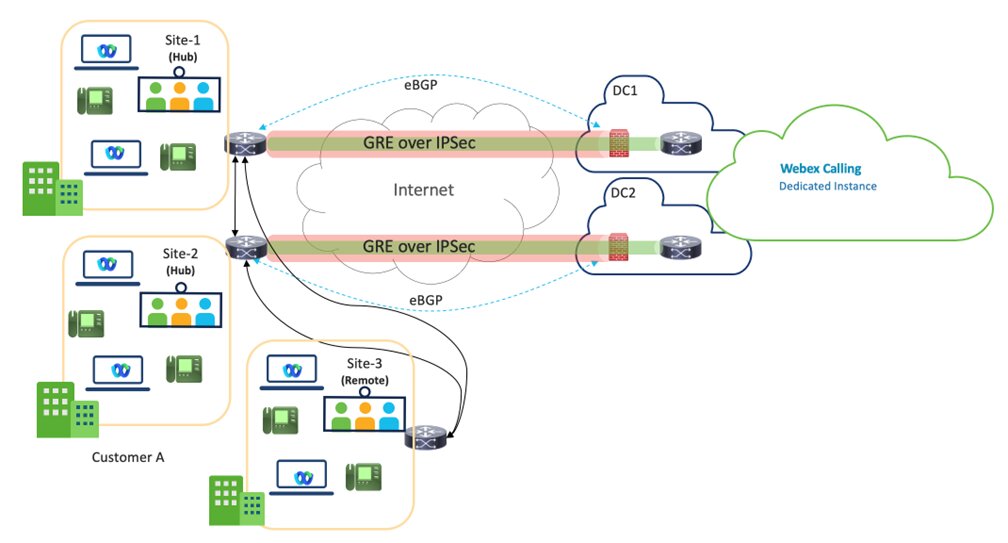
Virtual Connect - VPN is a Hub design, where the Customer’s Hub Sites are connected to DC1 and DC2 of Dedicated Instance’s datacenters within a particular region.
Two Hub sites are recommended for better redundancy, but One Hub site with two tunnels is also a supported deployment model.
The bandwidth per tunnel is limited to 250 Mbps. To ensure effective failover, the combined traffic across both tunnels must not exceed 250 Mbps, as all traffic will be routed through one tunnel in the event of a failure.
The Customer’s remote sites within the same region, would need to connect back to the Hub site(s) over the Customer’s WAN and it is not Cisco’s responsibility for that connectivity.
Partners are expected to work closely with the Customers, ensuring the most optimal path is chosen for the Virtual Connect service region.
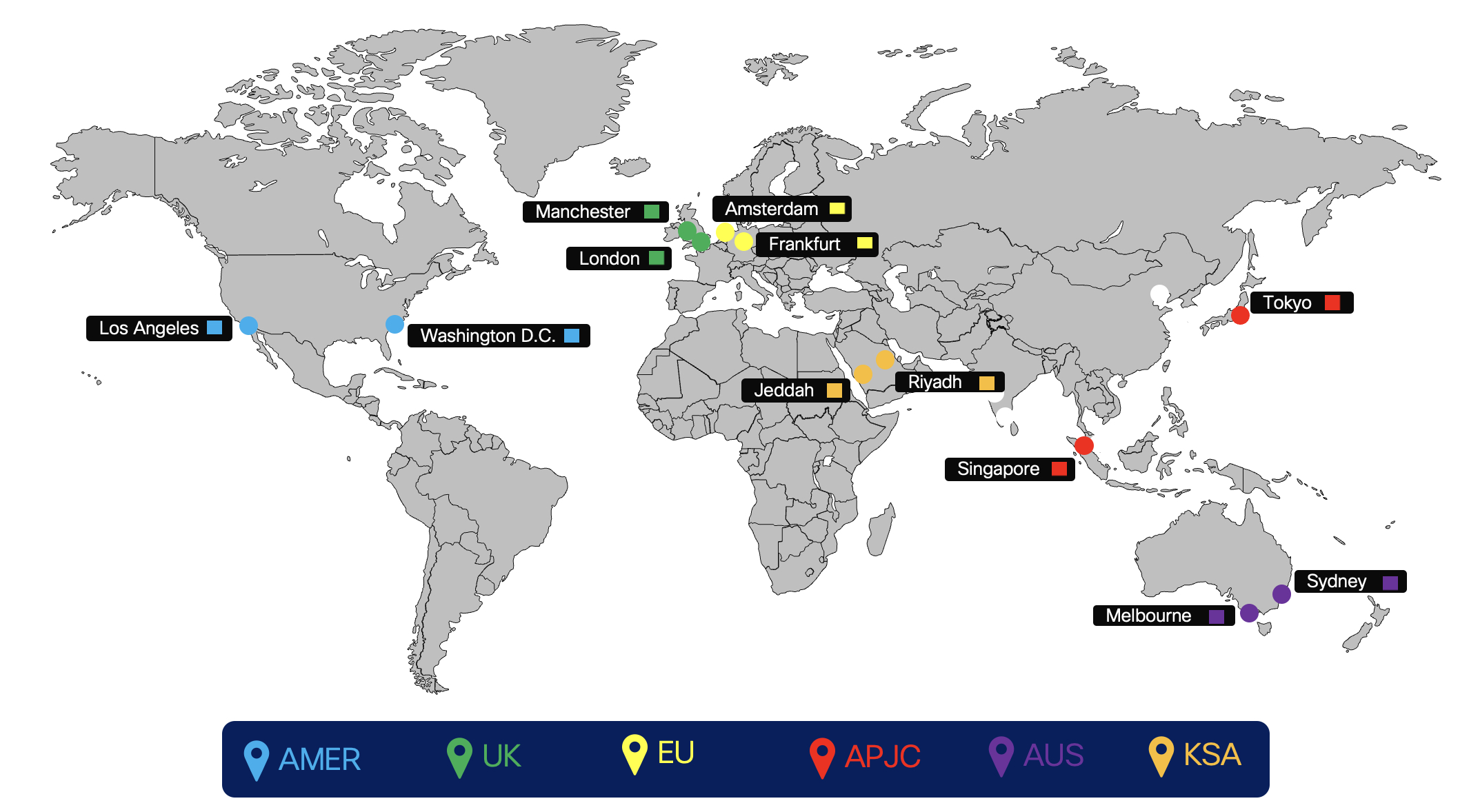
The below figure shows the Dedicated Instance cloud connectivity peering regions.
Routing
Routing for Virtual Connect add-on is implemented using external BGP (eBGP) between Dedicated Instance and the Customer Premise Equipment (CPE). Cisco will advertise their respective network for each redundant DC within a region to the Customer’s CPE and the CPE is required to advertise a default route to Cisco.
-
Cisco maintains and assigns
-
Tunnel Interface IP addressing (transient link for routing) Cisco assigns from a designated Shared Address Space (non-publicly routable)
-
Tunnel transport desitination address (Cisco's side)
-
Private autonomous system numbers (ASNs) for customer BGP routing configuration
-
Cisco assigns from the designated private use range: 64512 through 65534
-
-
-
eBGP used to exchange routes between Dedicated Instance and CPE
-
Cisco will split the assigned /24 network into 2 /25 one for each DC in the respective region
-
In Virtual Connect each /25 network is advertised back to CPE by Cisco over the respective point-to-point VPN tunnels (transient link)
-
CPE must be configured with the appropriate eBGP neighbors. If using one CPE, two eBGP neighbors will be used, one pointing to each remote tunnel. If using two CPE, then each CPE will have one eBGP neighbor poniting to the single remote tunnel for the CPE.
-
Cisco side of each GRE tunnel (tunnel interface IP) is configured as the BGP neighbor on the CPE
-
CPE is required to advertise a default route over each of the tunnels
-
CPE is responisible for redistributing, as required, the learned routes within the cutomer's enterprise network.
-
-
Under non-failure link failure condition, a single CPE will have two active/active tunnels. For two CPE nodes, each CPE will have one active tunnel and both CPE nodes should be active and passing traffic. Under non-failure scenario, traffic must split in two tunnels going to the correct /25 destinations, if one of the tunnel goes down, the remaining tunnel can carry the traffic for both. Under such a failure scenario, when the /25 network is down then the /24 network is used as a backup route. Cisco will send customer traffic via its internal WAN towards the DC which lost connectivity.
Virtual connect traffic flow
Traffic flow when both the tunnels are up
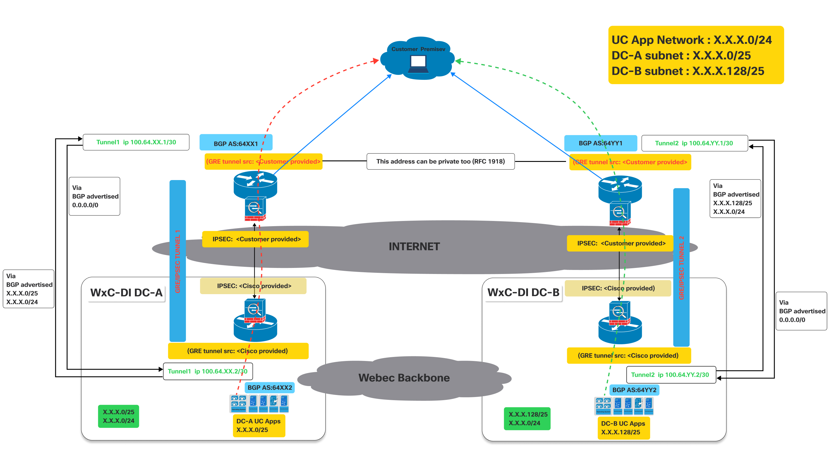
This image illustrates a Virtual Connect network architecture, detailing the traffic flow when both primary and secondary tunnels are operational.
It represents an active connectivity model for a customer to access UC applications hosted in Cisco's datacenters, leveraging dual GRE/IPSEC tunnels over the internet with BGP for route exchange.
Definitions:
- Customer Premise:
- This represents the customer's on-site network, where users and their devices (e.g., IP phones, computers running UC clients) are located.
- Traffic originating from here needs to reach the UC applications hosted in Cisco's datacenters.
- Cisco Webex Calling Dedicated Instance (Dedicated Instance) datacenters (WxC-DI
DC-A and WxC-DI DC-B):
- These are Cisco's datacenters hosting the UC applications.
- DC-A and DC-B are geographically distinct, providing redundancy.
- Each datacenter has its own subnet for UC applications:
- DC-A subnet:X.X.X.0/25
- DC-B subnet:X.X.X.128/25
- GRE/IPsec Tunnels (Tunnel 1 and Tunnel 2):
- These are the secure, encrypted connections between the customer premise and the Cisco datacenter over the public internet.
- GRE (Generic Routing Encapsulation): This protocol is used to encapsulate various network layer protocols inside virtual point-to-point links. It allows routing protocols like BGP to operate over the tunnel.
- IPsec (Internet Protocol Security): This suite of protocols provides cryptographic security services (authentication, integrity, confidentiality) for IP communications. It encrypts the GRE-encapsulated traffic, ensuring secure data transmission over the Internet.
- Border Gateway Protocol (BGP):
- BGP is the routing protocol used to exchange routing information between the customer premise and the Cisco datacenters.
As shown in the above diagram, devices deployed on customer premises need to establish two GRE/IPSEC tunnels.
The naming conventions used below with XX / YY, DC-A DC-B are generic for all regions where Dedicated Instance is offered . These values will be unique for each region and the actual values for each region. The specific values are provided during the activation of the virtual connect.
On Cisco side the IPSec and GRE tunnels will be terminated on different devices. So the customer has to make sure to configure IPSec destination and GRE destination IPs on the devices accordingly. Customers can use the same IP for GRE and IPSEC if it is supported on their devices. Refer to the diagram above. The IP related values are provided during activation of the virtual connect on the portal.
- Tunnel 1: Connects the customer premise to "Dedicated Instance DC-A" (Data Center A) via the Internet. This tunnel uses BGP AS:64XX1 on the customer side and BGP AS:64XX2 on the Dedicated Instance DC-A side. IPSEC and GRE tunnel source configurations are split between customer-provided and Cisco-provided details.
- Tunnel 2: Connects the customer premise to "Dedicated Instance DC-B" (Data Center B) via the Internet. This tunnel uses BGP AS:64YY1 on the customer side and BGP AS:64YY2 on the Dedicated Instance DC-B side. Like Tunnel 1, IPSEC and GRE tunnel source configurations are shared between the customer and Cisco.
In BGP AS:64XX and BGP AS:64YY, XX and YY are specific to a particular region.
Once the GRE/IPSEC tunnels are established to Webex Calling Dedicated Instance datacenters (A and B), customer should receive the following routes advertised from Cisco over the corresponding BGP sessions.
- For DC-A: Routes advertised from Cisco will be X.X.X.0/25 and X.X.x.0/24. Optionally if IaaS is requested and configured for the customer routes Y.Y.Y.0/25 and Y.Y.Y.0/24 will be advertised from Cisco.
- For DC-B: Routes advertised from Cisco will be X.X.X.128/25 and X.X.x.0/24. Optionally if IaaS is requested and configured for the customer routes Y.Y.Y.128/25 and Y.Y.Y.0/24 will be advertised from Cisco.
- Customer needs to advertise the 0.0.0./0 route to Cisco thru both the connections (tunnels)
- Customer has to follow the longest prefix (/25) routes to send traffic to Cisco thru the respective tunnels when both tunnels are up.
- Cisco will return the traffic thru the same tunnels to keep traffic symmetric.
Traffic Flow:
- Traffic destined for "DC-A UC Apps" (X.X.X.0/25) from the customer premise flows through Tunnel 1.
- Traffic destined for "DC-B UC Apps" (X.X.X.128/25) from the customer premise flows through Tunnel 2.
Fail over scenario : traffic flow when one of the tunnel is down
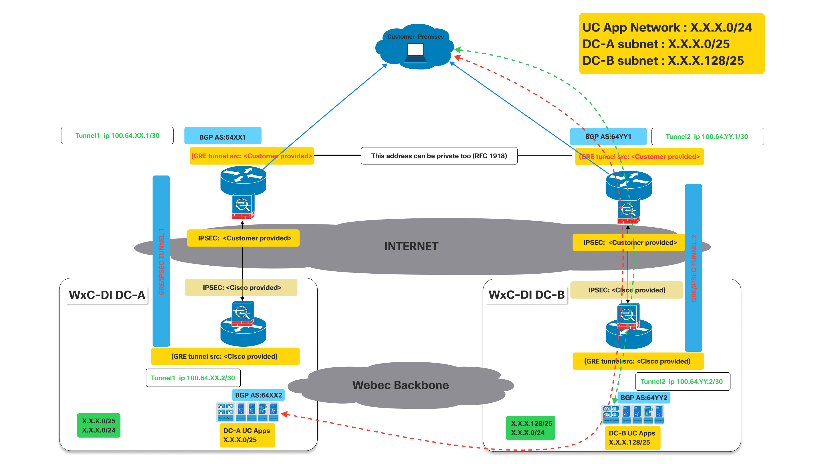
As shown in the above diagram when the tunnel to DC-A is down the bgp established thru tunnel to DC-A will go down.
Impact on BGP: When Tunnel 1 goes down, the BGP session over that tunnel will also go down. Consequently, DC-A will no longer be able to advertise its routes (specifically X.X.X.0/25) to the customer via this path. Hence the customer router will detect the path as unreachable.
Now since Tunnel 1 is down, the customer router at the customer premise will automatically remove the routes learned via Tunnel 1 from its routing table or mark them as unreachable.
- Traffic destined for the UC App Network (X.X.X.0/24) or the DC-A subnet (X.X.X.0/25) will then be redirected thru the working tunnel towards DC-B which continues to advertise the X.X.X.0/24 that includes the X.X.X.0/25 network.
- Similar behavior will be seen if tunnel to DC-B is down while tunnel to DC-A is still up.
Connectivity Process
| 1 | |
| 2 | |
| 3 | |
| 4 |
Step 1: CCW Order
Virtual Connect is an add-on for Dedicated Instance in CCW.
| 1 |
Navigate to the CCW ordering site and then click Login to sign on to the site: |
| 2 |
Create Estimate. |
| 3 |
Add "A-FLEX-3" SKU. |
| 4 |
Select Edit options. |
| 5 |
In the subscription tab that appears, Select Options and Add-ons. |
| 6 |
Under Additional Add-ons, select the check box beside "Virtual Connect for Dedicated Instance". The SKU name is "A-FLEX-DI-VC". |
| 7 |
Enter the quantity and number of regions in which Virtual Connect is required. The Virtual Connect quantity should not exceed the total number of regions purchased for Dedicated Instance. Also, only one Virtual Connect order is allowed per region. |
| 8 |
When you are satisfied with your selections, Click Verify and Save in the upper right portion of the page. |
| 9 |
Click Save and Continue to finalize your order. Your finalized order now appers in the order grid. |
Step 2: Activation of Virtual Connect in Control Hub
| 1 |
Sign in to Control Hub https://admin.webex.com/login. |
| 2 |
In the Services section, navigate to Calling > Dedicated Instacnce > Cloud Connectivity. |
| 3 |
In the Virtual Connect card, the purchased Virtual Connect quantity is listed. The administrator can now click on Activate to initiate the Virtual Connect activation. 
The activation process can be triggered only by Administrators with “Customer Full admin” Role. Whereas, an administrator with “Customer read-only admin” Role can only view the status. |
| 4 |
On clicking the Activate button, Activate Virtual Connect form is displayed for the administrator to provide the Virtual Connect technical details required for the peering configurations on the Cisco’s side. The form also provides static information on Cisco’s side, based on the Region selected. This information will be useful for Customer administrators to configure the CPE on their side to establish the Connectivity. |
| 5 |
Click on the Activate button once all the mandatory fields are filled. |
| 6 |
After the Virtual Connect Activation form is completed for a particluar region, the customer can Export the activation form from Control Hub, Calling > Dedicated Instance > Cloud Connectivity tab and click on Export settings. 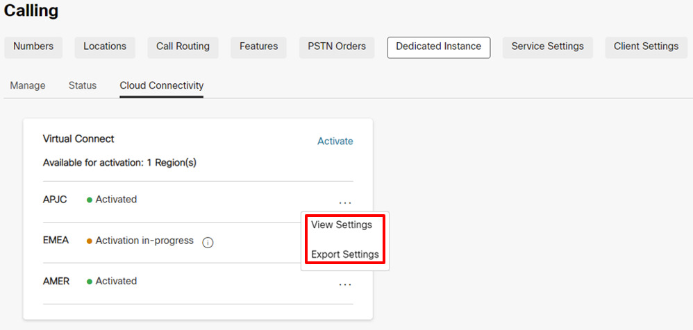
Due to security reasons the Authentication and BGP Password will not be available in the Exported document, but the administrator can view the same in Control Hub by clicking on View Settings under Control Hub, Calling > Dedicated Instance > Cloud Connectivity tab. |
Step 3: Cisco performs Network Configuration
| 1 |
Once the Virtual Connect Activation form is completed, the status will be updated to Activation In-Progress in Calling > Dedicated Instance > Cloud Connectivity Virtual Connect card. |
| 2 |
Cisco will complete the required configurations on the Cisco’s side equipment within 5 business days. On successful completion, the status will be updated to “Activated” for that particular region in Control Hub. |
Step 4: Customer performs Network Configuration
|
The status is changed to "Activated" to notify the Customer adminstrator that the Cisco's side of configurations for the IP VPN connectivity has ben completed based on the inputs provided by the Customer. But, the customer administrator is expected to complete their side of the configurations on the CPEs and test the connectivity routes for the Virtual Connect tunnel to be Online. In case of any issues faced at the time of configuration or connectivity, the customer can reach out to Cisco TAC for assistance. |
Troubleshooting
IPsec First Phase (IKEv2 Negotiation) Troubleshooting and Validation
The IPsec tunnel negotiation involves two phases, the IKEv2 phase and the IPsec phase. If the IKEv2 phase negotiation does not complete, then there is no initiation of a second IPsec phase. First, issue the command "show crypto ikev2 sa" (on Cisco equipment) or similar command on the third-party equipment to verify whether the IKEv2 session is active. If the IKEv2 session is not active, the potential reasons could be:
-
Interesting traffic does not triggers the IPsec tunnel.
-
The IPsec tunnel access list is misconfigured.
-
There is no connectivity between the customer and the Dedicated Instance IPsec tunnel endpoint IP.
-
The IKEv2 session parameters are not matching between the Dedicated Instance side and the customer side.
-
A firewall is blocking the IKEv2 UDP packets.
First, check the IPsec logs for any messages that show the progress of the IKEv2 tunnel negotiation. The logs may indicate where there is an issue with the IKEv2 negotiation. A lack of logging messages may also indicate that the IKEv2 session is not being activated.
Some common errors with the IKEv2 negotiation are:
-
The settings for the IKEv2 on the CPE side do not match the Cisco side, recheck the settings mentioned:
-
Check that the IKE version is version 2.
-
Verify that the Encryption and Authentication parameters match the expected encryption on the Dedicated Instance side.
When the "GCM" cipher is in use, the GCM protocol handles the authentication and set the authentication parameter to NULL.
-
Verify the lifetime setting.
-
Verify the Diffie Hellman modulus group.
-
Verify the Pseudo Random Function settings.
-
-
The access list for the crypto map is not set to:
-
Permit GRE (local_tunnel_transport_ip) 255.255.255.255 (remote_tunnel_transport_ip) 255.255.255.255" (or equivalent command)
The access list must be specifically for the "GRE" protocol and the "IP" protocol will not work.
-
If the log messages are not showing any negotiation activity for the IKEv2 phase, then a packet capture may be needed.
Dedicated Instance side may not always begin the IKEv2 exchange and may sometimes expect the customer CPE side to be the initiator.
Check the CPE side configuration for the following prerequisites for IKEv2 session initiation:
-
Check for an IPsec crypto access list for GRE traffic (protocol 50) from the CPE tunnel transport IP to the Dedicated Instance tunnel transport IP.
-
Ensure that the GRE tunnel interface is enabled for GRE keepalives, if the equipment does not support GRE keepalives then Cisco is notified because GRE keepalives will be enabled on the Dedicated Instance side on default.
-
Ensure that BGP is enabled and configured with the neighbor address of the Dedicated Instance tunnel IP.
When configured properly, the following begins the IPsec tunnel and the first-phase IKEv2 negotiation:
-
GRE keepalives from the CPE side GRE tunnel interface to the Dedicated Instance side GRE tunnel interface.
-
BGP neighbor TCP session from the CPE side BGP neighbor to the Dedicated Instance side BGP neighbor.
-
Ping from the CPE side tunnel IP address to the Dedicated Instance side tunnel IP address.
Ping cannot be the tunnel transport IP to tunnel transport IP, it must be tunnel IP to tunnel IP.
If a packet trace is needed for the IKEv2 traffic, set the filter for UDP and either port 500 (when no NAT device is in the middle of the IPsec endpoints) or port 4500 (when a NAT device is inserted in the middle of the IPsec endpoints).
Verify that IKEv2 UDP packets with port 500 or 4500 are sent and received to and from the DI IPsec IP address.
The Dedicated Instance datacenter may not always begin the first IKEv2 packet. The requirement is that the CPE device is capable of initiating the first IKEv2 packet toward the Dedicated Instance side.
If the local firewall allows it, then also attempt a ping to the remote IPsec address. If the ping is not successful from local to remote IPsec address, then perform a trace route to help, and determine where the packet is dropped.
Some firewalls and internet equipment may not allow trace route.
IPsec Second Phase (IPsec Negotiation) Troubleshooting and Validation
Verify that the IPsec first phase (that is, IKEv2 security association) is active before troubleshooting the IPsec second phase. Perform a "show crypto ikev2 sa" or equivalent command to verify the IKEv2 session. In the output, verify that the IKEv2 session has been up for more than a few second and that it is not bouncing. The session uptime shows as the session "Active Time" or equivalent in output.
Once the IKEv2 session verifies as up and active, Investigate the IPsec session. As with the IKEv2 session, perform a "show crypto ipsec sa" or equivalent command to verify the IPsec session. Both the IKEv2 session and the IPsec session must be active before the GRE tunnel is established. If the IPsec session does not show as active, check the IPsec logs for error messages or negotiation errors.
Some of the more common issues that may be encountered during the IPsec negotiations are:
The settings on the CPE side do not match the Dedicated Instance side, recheck the settings:
-
Verify that the Encryption and Authentication parameters match the settings on the Dedicated Instance side.
-
Verify the Perfect Forward Secrecy settings and that the match settings on the Dedicated Instance side.
-
Verify the lifetime settings.
-
Verify that the IPsec has been configured in tunnel mode.
-
Verify the source and destination IPsec addresses.
Tunnel Interface Troubleshooting and Validation
When the IPsec and IKEv2 sessions are verified as up and active, the GRE tunnel keepalive packets able to flow between the Dedicated Instance and CPE tunnel endpoints. If the tunnel interface is not showing up status, some common issues are:
-
The tunnel interface transport VRF does not match the VRF of the loopback interface (if VRF configuration is used on the tunnel interface).
If the VRF configuration is not used on the tunnel interface, this check can be ignored.
-
Keepalives are not enabled on the CPE side tunnel interface
If keepalives are not supported on the CPE equipment, then Cisco must be notified so that the default keepalives on the Dedicated Instance side are disabled as well.
If keepalives are supported, verify that the keepalives are enabled.
-
The mask or IP address of the tunnel interface is not correct and does not match the Dedicated Instance expected values.
-
The source or destination tunnel transport address is not correct and does not match the Dedicated Instance expected values.
-
A firewall is blocking GRE packets from sent into the IPsec tunnel or received from the IPsec tunnel (the GRE tunnel is transported over the IPsec tunnel)
A ping test should verify that the local tunnel interface is up and connectivity is good to the remote tunnel interface. Perform the ping check from the tunnel IP (not the transport IP) to the remote tunnel IP.
The crypto access list for the IPsec tunnel which is carrying the GRE tunnel traffic allows only GRE packets to cross. As a result, pings will not work from tunnel transport IP to remote tunnel transport IP.
The ping check results in a GRE packet that is generated from the source tunnel transport IP to destination tunnel transport IP while the payload of the GRE packet (the inside IP) will be the source and destination tunnel IP.
If the ping test is not successful and the preceding items are verified, then a packet capture may be required to ensure that the icmp ping is resulting in a GRE packet which is then encapsulated into an IPsec packet and then sent from the source IPsec address to the destination IPsec address. Counters on the GRE tunnel interface and the IPsec session counters can also help to show. if the send and receive packets are incrementing.
In addition to the ping traffic, the capture should also show keepalive GRE packets even during idle traffic. Finally, if BGP is configured, BGP keepalive packets should also be sent as GRE packets encapsulated in IPSEC packets as well over the VPN.
BGP Troubleshooting and Validation
BGP Sessions
BGP is required as the routing protocol over the VPN IPsec tunnel. The local BGP neighbor should establish an eBGP session with the Dedicated Instance BGP neighbor. The eBGP neighbor IP addresses are the same as the local and remote tunnel IP addresses. First ensure that the BGP session is up and then verify that the correct routes are being received from Dedicated Instance and the correct default route is sent to Dedicated Instance.
If the GRE tunnel is up, verify that a ping is successful between the local and the remote GRE tunnel IP. If the ping is successful but the BGP session is not coming up, then investigate the BGP log for BGP establishment errors.
Some of the more common BGP negotiation issues are:
-
The remote AS number does not match the AS number that is configured on the Dedicated Instance side, re-check the neighbor AS configuration.
-
The local AS number does not match what the Dedictaed Instance side is expecting, verify that the local AS number matches the expected Dedicated Instance parameters.
-
A firewall is blocking BGP TCP packets encapsulated in GRE packets from being sent into the IPsec tunnel or being received from the IPSEC tunnel
-
The remote BGP neighbor IP does not match the remote GRE tunnel IP.
BGP Route Exchange
Once the BGP session is verified for both tunnels, ensure that the correct routes are being send and received from the Dedicated Instance side.
The Dedicated Instance VPN solution expects two tunnels to be established from the customer/partner side. The first tunnel points to the Dedicated Instance datacenter A and the second tunnel points to the Dedicated Instance datacenter B. Both tunnels must be in active state and the solution requires an active/active deployment. Each Dedicated Instance datacenter will advertise it's local /25 route as well as a /24 backup route. When checking the incoming BGP routes from Dedicated Instance, ensure that the BGP session associated with the tunnel pointing to Dedicated Instance datacenter A receives the Dedicated Instance datacenter A /25 local route as well as the /24 backup route. In addition, ensure that the tunnel pointing to Dedicated Instance datacenter B recieves the Dedicated Instance datacenter B /25 local route as well as the /24 backup route. Note that the /24 backup route will be the same route advertised out of Dedicated Instance datacenter A and Dedicated Instance datacenter B.
Redundancy is provided to a Dedicated Instance datacenter if the tunnel interface to that datacenter goes down. If connectivity to Dedicated Instance datacenter A is lost, then traffic will be forwarded from Dedicated Instance datacenter B to datacenter A. In this scenario, the tunnel to datacenter B will use the datacenter B /25 route to send traffic to datacenter B and the tunnel to datacenter B will use the backup /24 route to send traffic to datacenter A via datacenter B.
It is important that, when both tunnels are active that datacenter A tunnel is not used to send traffic to datacenter B and vice versa. In this scenario, if traffic is sent to datacenter A with a destination of datacenter B, datacenter A will forward the traffic to datacenter B and then datacenter B will attempt to send traffic back to the source via the datacenter B tunnel. This will result in sub-optimal routing and may also break traffic traversing firewalls. Therefore, it is important for both tunnels to be in an active/active configuration during normal operation.
The 0.0.0.0/0 route must be advertised from the customer side to the Dedicated Instance datacenter side. More specific routes will not be accepted by the Dedicated Instance side. Ensure that the 0.0.0.0/0 route is advertised out of both the Dedicated Instance datacenter A tunnel and the Dedicated Instance datacenter B tunnel.
MTU Configuration
In the Dedicated Instance side, two features are enabled to dynamically adjust MTU for large packet sizes. The GRE tunnel adds more headers to the IP packets flowing through the VPN session. The IPsec tunnel adds the additional headers on top of the GRE headers will further reduce the largest MTU allowed over the tunnel.
The GRE tunnel adjusts MSS feature and GRE tunnel path in the MTU discovery feature is enabled on the Dedicated Instance side. Configure "ip tcp adjust-mss 1350" or equivalent command as well as "tunnel path\u0002mtu-discovery" or equivalent command on the customer side to help with the dynamic adjusting of MTU of traffic through the VPN tunnel.


