- Home
- /
- Article

Thanks for your feedback.

Get started with your new Cisco IP DECT 6800 series
 In this article
 Feedback?
As a local administrator, you need to set up the base station and handsets in your location.
System setup
The Cisco IP DECT Solution can use any combination of the Cisco devices listed below:
-
Cisco IP DECT DBS 110 Single-Cell Base Station (can only be used with other DBS-110)
-
Cisco IP DECT 210 Multi-Cell Base Station (can only be used with other DBS-210)
-
Cisco IP DECT Phone 6823 Handset
-
Cisco IP DECT Phone 6825 Handset: Standard and Ruggedized Handsets
Together, these products enable the convenience of a mobile DECT solution for the Webex Carrier and Webex Calling platforms. When you get your new base station and handsets, you need to:
-
Unpack at least one handset and charging cradle. Charge the handset on the charging cradle for 10 hours before you use it. See these articles for more information:
-
Each handset has a unique International Portable Equipment Identity (IPEI) number listed on the product box or in the battery compartment. Make a list of each IPEI number and collect this information for each handset:
-
Phone numbers
-
Assigned user name and password for Webex Calling
-
BroadSoft XSI user name and password (if required)
-
Voicemail name and number
-
-
Use the site survey tool on the handset to determine the best place to install the base station. For more information, see Perform a Site Survey for Your Cisco IP DECT 6800 Series
-
Install the base station on the wall, ceiling, or desk. Connect the base station to the LAN and provide power to the base station if your LAN doesn't support Power over Ethernet (PoE).
-
Allow the base station to automatically configure. The base station communicates with servers for configuration and provisioning information.
-
After the base station is configured, you connect to the base station web page from your computer and configure the handsets.
-
After the handsets are configured, you turn on the fully-charged handsets and set them up to communicate with the base station.
-
With the handsets set up, you can distribute the handsets to the users. Make sure that you give the users their voicemail PINs and this URL: https://help.webex.com. This site gives the users instructions on handset use.
Device comparison on the DECT base stations and repeaters
The following table lists the device comparisons of the Cisco IP DECT DBS-110 Single-Cell Base Station and the Cisco IP DECT DBS-210 Multi-Cell Base Station.
|
Feature |
Details |
|---|---|
|
Unit Capacity: Single-Cell Mode |
DECT 110 Single-Cell Base Station: Up to 30 SIP Registrations and Up to 10 Concurrent Calls
DECT 210 Multi-Cell Base Station: Up to 30 SIP registrations and Up to 10 Concurrent Calls |
|
Multi-Cell Mode: |
DECT 110 Single-Cell Base Station: Supported in single or dual cell mode with 2 Base Stations Deployed: Up to 30 SIP Registrations and Up to 20 Concurrent Calls DECT Networks using DECT 210 Base Stations with 250 Base Stations Deployed: Up to 1000 SIP Registrations and Up to 2000 Concurrent Calls |
|
Base Stations and Repeaters: Single-Cell Mode: |
DECT 110 Single-Cell Base Station: 1 Base Station and Up to 6 Repeaters
DECT 210 Multi-Cell Base Station: 1 Base Station and Up to 3 Repeaters |
|
Multi-Cell Mode |
DECT 110 Single-Cell Base Station: Not Supported in Multi-Cell Mode
DECT 210 Multi-Cell Base Station: Up to 250 Base stations or up to 50 Base stations and 100 Repeaters |
|
Call control and audio features |
|
Features and benefits of the Cisco IP 6823 and the Cisco IP 6825
The following table lists the features and benefits of the Cisco IP DECT DBS-110 Single-Cell Base Station and the Cisco IP DECT DBS-210 Multi-Cell Base Station.
|
Feature |
Benefits |
|---|---|
|
Ergonomic Design |
An easy-to-use interface providing traditional Digital Enhanced Cordless Telecommunication (DECT) telephony-like user experience |
|
Graphical Display |
6823: 128 x 160 pixels, 64K TFT display 6825: 240 x 320 pixels, 64K TFT display Both handsets: 3-color MWI LED |
|
Handset (HAC) |
All 6825 Handsets are Hearing-Aid-Compatible (HAC) and meet Federal Communications Commission (FCC) loudness requirements for the Americans with Disabilities Act (ADA)
You can meet Section 508 loudness requirements by using industry-standard inline handset amplifiers such as Walker Equipment W-10 or CE-100 amplifiers
HAC compliant – FCC part 68 and Australia S040 |
|
Headset |
6825 only: Bluetooth LE 4.1 6823 and 6825: 3.5 mm wired headset, iPhone compliant
The 6800 series provides exceptional noise isolation when used with a Cisco Headset |
|
Volume Control |
A volume-control toggle provides easy decibel-level adjustments of the handset, monitor speaker, and ringer |
|
Keys |
|
|
Battery Life |
|
|
Full lines supported |
6823 and 6825: 2 lines (SIP registrations) |
|
Weight |
6823 and 6825: 3 oz. (86 g) |
|
Display |
6823: 1.7 in. (4.3 cm) 128 x 160 pixels, 64K TFT display 6825: 2.0 in. (5.0 cm), 240 x 320 pixels, 64K TFT display |
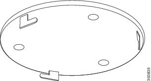
Mount the base station or repeater on the ceiling
You can mount the base station or repeater on a ceiling. They use a custom ceiling mount bracket that you can install on the ceiling. You need to order the ceiling mount bracket.
You can mount the base station on a ceiling. The base station has a custom ceiling mount bracket that you can install on the ceiling. You need to order the ceiling mount bracket.
Each base station has a range of up to 984 feet (300 meters).
The base station and repeater have a range of up to 984 feet (300 meters) outdoors and a range of 164 feet (50 meters) indoors.
In this task, the term device means the base station or repeater.
Before you begin
You need:
-
Ceiling mount bracket
-
Pencil
-
Mounting hardware (screws and plugs) suitable for the ceiling construction.
-
Base station: LAN connection close to the mounting location.
-
Base station: If you do not use PoE, a power outlet close to the mounting location.
-
Repeater: A power outlet close to the mounting location.
-
Ensure that the base station can communicate with the network (see Install the Base Station). After it can communicate and the LED is green, you can unplug the cables.
Determine the best placement, taking into account the coverage area and the building construction materials. You may need to install addition base stations for best coverage.
Determine the best placement, taking into account the coverage area and the building construction materials.
-
If you have a 110 Single-Cell Base Station, you may need to add another 110 Single-Cell Base Station or additional 110 Repeaters.
-
If you have a 210 Multi-Cell Base Station, you may need to add additional base stations or repeaters.
-
If you have a 110 Single-Cell Base Station, you may need to add 110 Repeaters.
-
If you have a 210 Multi-Cell Base Station, you may need to add additional base stations or repeaters.
You can use the site survey tool on the handset to plan placement.
You can use the site survey tool on the handset to plan the placement. See Perform a Site Survey for Your Cisco IP DECT 6800 Series.
| 1 |
Hold the ceiling mount bracket in the desired location. |
| 2 |
Mark the screw placement. 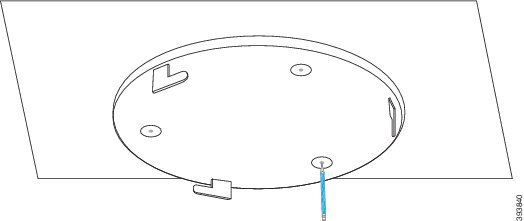
|
| 3 |
Install the plugs as described by the manufacturer. |
| 4 |
Install the screws through the bracket and into the plugs. 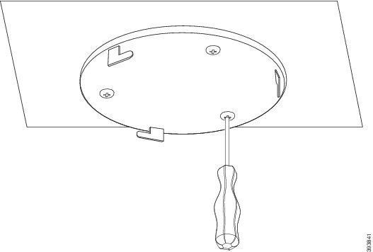
|
| 5 |
Base station only: Connect the Ethernet cable to the device and route the cable through the slot in the device. |
| 6 |
Provide power to the device:
|
| 7 |
Plug the power adapter into the device and route the cable through the slot in the device. |
| 8 |
Align the slots in the bracket with the slots in the device and turn left until the device locks in place. This graphic shows the alignment of the mounting bracket to the base station. The back of the repeater is similar to the base station. 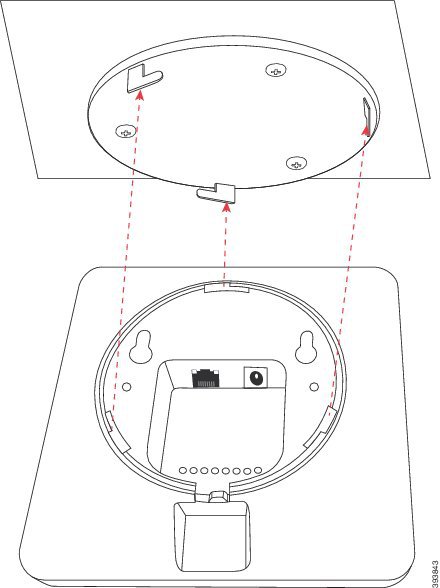
This diagram shows the way you turn the device to lock it into the mounting bracket. 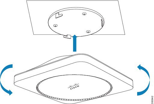
|
| 9 |
Base station only: Plug the Ethernet cable into the LAN port. |
| 10 |
If required, plug the power adapter into the electrical outlet. If the base station LED lights green, it can connect to the network and start to download its configuration. |
What to do next
Do one of these:
-
Base station installation:
-
Manual configuration: Sign in to the administration web page and Configure the Base Station
-
Automatic configuration: Sign in to the administration web page and Start handset registration
-
-
Repeater installation: Add a Repeater
Mount the base station or repeater on a desk
You can place the base station on a desk or other horizontal surface (for example, a book shelf). Select a location where the base station won't be easily knocked off.
You can place the base station or repeater on a desk or other horizontal surface (for example, a book shelf). Select a location where the base station or repeater won't be easily knocked off.
Each base station has a range of up to 984 feet (300 meters).
The base station and repeater have a range of up to 984 feet (300 meters) outdoors and a range of 164 feet (50 meters) indoors.
In this task, the term device means the base station or repeater.
Before you begin
You need:
-
Base station: LAN connection close to the mounting location.
-
Base station: If you do not use PoE, a power outlet close to the mounting location.
-
Repeater: A power outlet close to the mounting location.
-
Ensure that the base station can communicate with the network (see Install the Base Station). After it can communicate and the LED is green, you can unplug the cables if you haven't tested the base station in the final location.
Determine the best placement, taking into account the coverage area and the building construction materials. You may need to install addition base stations for best coverage.
Determine the best placement, taking into account the coverage area and the building construction materials.
-
If you have a 110 Single-Cell Base Station, you may need to add another 110 Single-Cell Base Station or additional 110 Repeaters.
-
If you have a 210 Multi-Cell Base Station, you may need to add additional base stations or repeaters.
-
If you have a 110 Single-Cell Base Station, you may need to add 110 Repeaters.
-
If you have a 210 Multi-Cell Base Station, you may need to add additional base stations or repeaters.
You can use the site survey tool on the handset to plan placement.
You can use the site survey tool on the handset to plan the placement. See Perform a Site Survey for Your Cisco IP DECT 6800 Series.
| 1 |
Base station only: Connect the Ethernet cable to the device and route the cable through the slot in the device. |
| 2 |
Provide power to the device:
|
| 3 |
If required, plug the power adapter into the device and route the cable through the slot in the device. |
| 4 |
Slide the stand into the device and press it until it clicks into place. This graphic shows the stand connection to the base station. The back of the repeater is similar to the base station. 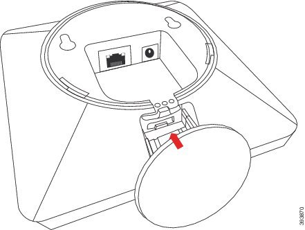
|
| 5 |
Base station only: Plug the Ethernet cable into the LAN port. |
| 6 |
If required, plug the power adapter into the electrical outlet. If the base station LED lights green, it can connect to the network and start to download its configuration. |
What to do next
Do one of these:
-
Base station installation:
-
Manual configuration: Sign in to the administration web page and Configure the Base Station
-
Automatic configuration: Sign in to the administration web page and Start handset registration
-
-
Repeater installation: Add a Repeater
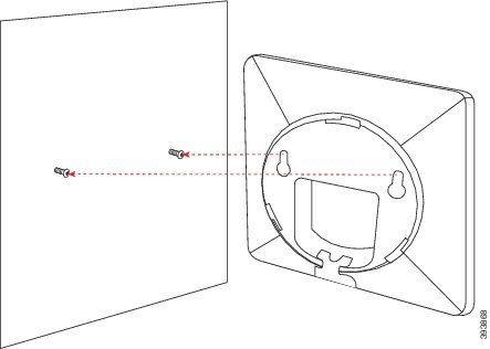
Mount the base station or repeater on the wall
You can mount the base station or repeater on a wall. You put two screws into the wall and slip the base station or repeater onto the screw heads or you can use the ceiling mount bracket.
You can mount the base station on a wall. You put two screws into the wall and slip the base station onto the screw heads or you can use the ceiling mount bracket.
We recommend that you mount the base station or repeater as high as possible on a wall. If possible, mount it at a downward facing angle for better radio coverage.
We recommend that you mount the base station as high as possible on a wall. If possible, mount it at a downward facing angle for better radio coverage.
Each base station has a range of up to 984 feet (300 meters).
The base station and repeater have a range of up to 984 feet (300 meters) outdoors and a range of 164 feet (50 meters) indoors.
In this task, the term device means the base station or repeater.
Before you begin
You need:
-
Pencil
-
Level
-
Tape measure
-
Mounting hardware (screws and wall plugs) suitable for the wall construction. You can also use the ceiling mount bracket.
-
Base station: LAN connection close to the mounting location.
-
Base station: If you do not use PoE, a power outlet close to the mounting location.
-
Repeater: A power outlet close to the mounting location.
-
Ensure that the base station can communicate with the network (see Install the Base Station). After it can communicate and the LED is green, you can unplug the cables.
Determine the best placement, taking into account the coverage area and the building construction materials. You may need to install addition base stations for best coverage.
Determine the best placement, taking into account the coverage area and the building construction materials.
-
If you have a 110 Single-Cell Base Station, you may need to add another 110 Single-Cell Base Station or additional 110 Repeaters.
-
If you have a 210 Multi-Cell Base Station, you may need to add additional base stations or repeaters.
-
If you have a 110 Single-Cell Base Station, you may need to add 110 Repeaters.
-
If you have a 210 Multi-Cell Base Station, you may need to add additional base stations or repeaters.
You can use the site survey tool on the handset to plan placement.
You can use the site survey tool on the handset to plan the placement. See Perform a Site Survey for Your Cisco IP DECT 6800 Series.
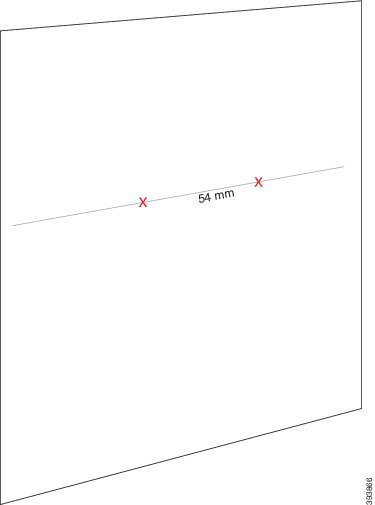
| 1 |
Hold the level in the desired location and at least 2.25 inches (5.7 cm) below the ceiling, and draw a level line. 
|
| 2 |
Mark the placement of the screws.
|
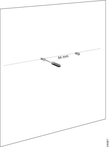
| 3 |
Install the wall plugs as described by the manufacturer. |
| 4 |
Insert the screws.
|
| 5 |
Base station only: Connect the Ethernet cable to the base station and route the cable through the slot in the base station. |
| 6 |
Provide power to the device:
|
| 7 |
Plug the power adapter into the device and route the cable through the slot in the device. |
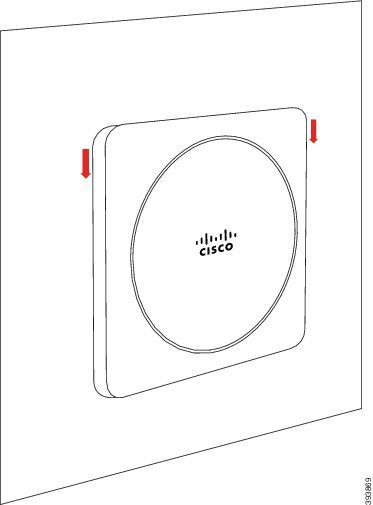
| 8 |
Put the device on the wall.
|
| 9 |
Base station only: Plug the Ethernet cable into the LAN port. |
| 10 |
If required, plug the power adapter into the electrical outlet. If the base station LED lights green, it can connect to the network and start to download its configuration. |
What to do next
Do one of these:
-
Base station installation:
-
Manual configuration: Sign in to the administration web page and Configure the Base Station
-
Automatic configuration: Sign in to the administration web page and Start handset registration
-
-
Repeater installation: Add a Repeater
Find the base station IP address
You use the handset to find the IP address of the base stations in your network. The handset displays the IP address of every base station within range.
If you have access to your router administration page, you can also use it to find the IP address.
You may find the Base Station Worksheet useful to track your configuration.
Before you begin
You need these:
-
The base station needs to be connected into the network.
-
A handset needs to be available with a charged battery.
| 1 |
Press and hold Power/End |
| 2 |
Press Menu |
| 3 |
Enter |
Sign in to the administration web page
You use the base station web page to configure the base station and handsets.
Contact your service provider to determine if you connect to the base station with HTTP or HTTPS. This procedure assumes that you use HTTP.
The web page signs you out after five minutes of inactivity.
Before you begin
You need the IP address of the base station.
You need the MAC and IP address of the base station.
The base station needs to be connected to the network and the green LED lit.
| 1 |
Find the IP address of the base station with Find the base station IP address. |
| 2 |
In a browser, enter the address of the base station. Format:
where:
Example
|
| 3 |
Sign in to the base station as the administrator. We strongly recommend that you change the default password. For more information, see Change the Web Page Administrator or User Password. We strongly recommend that you change the default administrator and user password. For more information, see Change the Web Page Administrator or User Password. |
| 4 |
Sign in to the base station with these credentials:
|
Assign handsets to users
Your base station has been preconfigured with the handset information (for example, extension and username).
When you set up multiple handsets, you need to assign each handset to a specific user. Each user has a unique phone number and voicemail box, and may have different features.
When you set up multiple handsets, you need to assign each handset to a specific user. Each user has a unique phone number and voicemail box, and may have different features. You can assign individual access code to each handset with the Terminal web page fields or in the configuration file (.xml). You can set the access code this way in the configuration file:
<Subscr_Dect_Ac_Code_x_>nnnn</Subscr_Dect_Ac_Code_x_>x is the handset number and nnnn is the access code.
If the access code is more than 4 digits, only the first 4-digits are accepted.
To assign the handset to the user, you assign the International Portable Equipment Identity (IPEI) number of the handset to the correctly configured extension. The IPEI number for the handset is located in these locations:
-
On the label of the box that contained the handset
-
Under the handset battery
You may find the Handset Configuration Parameters Worksheet helpful.
Before you begin
Connect to the base station web page as described in Sign in to the administration web page.
The base station needs to be connected to the network and the green LED lit.
The handsets need to be set up as described in Add Handsets to the Base Station.
| 1 |
Click Extensions. |
| 2 |
Make note of the code in the AC field. |
| 3 |
Click the link in the IPEI column for the handset for a specific user. The IPEI link shows the IPEI number as |
| 4 |
Click the link in the Extension Info column for the handset for a specific user. The IPEI link shows the null IPEI number |
| 5 |
In the Terminal page, set the |
| 6 |
Set the AC field to match the code you captured in step 2. |
| 7 |
Set the AC field. |
| 8 |
(Optional) Configure the other fields, as described in Terminal Web Page Fields for Firmware Release V450 and V460. |
| 9 |
(Optional) Configure the other fields, as described in Terminal Web Page Fields. |
| 10 |
Click Save. |
| 11 |
(Optional) Repeat steps 3 to 7 to set up more handsets. |
What to do next
Terminal Web Page Fields
These are the fields displayed on the Terminal web page of the base station. You click on the IPEI number of the handset in the Extensions page to see this screen.
The page displays in admin and user views. Not all fields are available in user view.
This section is applicable to Firmware Release 4.7. For the page for Firmware Release V450 and V460, see Terminal Web Page Fields for Firmware Release V450 and V460.
|
Field |
Contents |
Description |
|---|---|---|
|
IPEI |
10 character string |
Identifies the International Portable Equipment Identity (IPEI) of the handset. Each handset has a unique IPEI number, and the number is displayed on the label under the handset battery and on the label of the handset box. If you change this field, the handset deregisters. |
|
Paired Terminal |
Values:
|
Identifies the terminal paired with the handset. |
|
AC |
4 digit code |
Identifies the access code that was used to register the handset. After the handset registers, this code is not used. We recommend that you change this from the default when you start to set up your system to increase security. |
|
Alarm Line |
Values:
|
Identifies the line to be used for alarm calls. |
|
Alarm Number |
Phone number |
Identifies the number to be dialed when a user presses and holds the Emergency |
|
Dial Plan ID |
Values: 1 to 10 |
Admin view only This field is new for Firmware Release 5.1(1). Identifies the index of the dial plan, configured in Dial Plans Web Page Fields. |
|
HEBU Username |
String up to 40 characters |
This field is new for Firmware Release 5.1(1). Indicates the username for the handset registration in HEBU mode. |
|
HEBU Password |
String up to 40 characters |
This field is new for Firmware Release 5.1(1). Indicates the password for the handset registration in the HEBU mode. |
|
Extensions | ||
|
VoIP Idx |
This field is read-only. |
Identifies the index of the handset. |
|
Extension |
This field is read-only. |
Identifies the configured extension name. The extension must be configured on the SIP server before the handset can make and receive calls. Admin view only: This field is a link to further information about the handset in the Edit extension page. |
|
Display Name |
This field is read-only. |
Identifies the telephone number. This information displays on the main screen of the handset. |
|
Server |
This field is read-only. |
Identifies the SIP server address of the call control system. |
|
Server Alias |
This field is read-only. |
Identifies the name of the call control system. |
|
State |
This field is read-only. |
Identifies the SIP registration state. If the field is empty, the handset isn't SIP-registered. |
|
Beacon Settings | ||
|
Receive Mode |
Admin view only Reserved for future use. | |
|
Transmit Interval |
Admin view only Reserved for future use. | |
|
Alarm Profiles | ||
|
Profile 0 to 7 |
|
Admin view only Indicates the list of alarms. |
|
Alarm Type |
Name of the alarm |
Admin view only Indicates which alarm type is configured for the particular profile. When no alarms are configured, the field displays |
|
Alarm Type check box |
Check box (default unchecked) |
Admin view only Identifies the alarm type that is active on the handset. |
|
Shared Call Appearance Settings | ||
|
Idx 1 to 8 |
|
Admin view only Index of the extensions |
|
Extension |
Extension number |
Admin view only Identifies the handset lines that support Shared Call Appearances. When no lines support the feature, the field displays |
|
Import Local Phonebook |
Filename |
Used to upload a local directory from a computer to the phone in comma separated value (CSV) format. For more information, see Local Contacts Setup. |
|
Export Local Phonebook |
|
Used to export a local directory from a phone to the computer in CSV format. For more information, see Local Contacts Setup. |
Terminal Web Page Fields for Firmware Release V450 and V460
These are the fields displayed on the Terminal web page of the base station. You click on the IPEI number of the handset in the Extensions page to see this screen.
The page displays in admin and user views. Not all fields are available in user view.
This section is applicable to Firmware Release V450 and V460. For Firmware Release 4.7, see Terminal Web Page Fields.
|
Field |
Contents |
Description |
|---|---|---|
|
IPEI |
10 character string |
Identifies the International Portable Equipment Identity (IPEI) of the handset. Each handset has a unique IPEI number, and the number is displayed on the label under the handset battery and on the label of the handset box. If you change this field, the handset deregisters. |
|
Paired Terminal |
Values:
|
Identifies the terminal paired with the handset. |
|
AC |
4 digit code |
Identifies the access code that was used to register the handset. After the handset registers, this code is not used. We recommend that you change this from the default when you start to set up your system to increase security. |
|
Alarm Line |
Values:
|
Identifies the line to be used for alarm calls. |
|
Alarm Number |
Phone number |
Identifies the number to be dialed when a user presses and holds the Emergency |
|
Dial Plan ID |
Values: 1 to 10 |
Admin view only Identifies the index of the dial plan, configured in Dial Plans Web Page Fields. Identifies the internal dial plan. |
|
Battery and RSSI Status | ||
|
Battery level |
Percentage |
Read-only field Displays the current charge level of the handset battery. |
|
RSSI |
|
Read-only field Displays the Received Signal Strength Indicator (RSSI) for the connected base station. Displays the Received Signal Strength Indicator (RSSI) for the connected base station or repeater. |
|
Measured time [mm:ss] |
|
Read-only field Displays the time in minutes and seconds since the battery and RSSI information was captured from the handset. |
|
Located |
|
Read-only field Identifies the base station with which the handset communicates. Identifies the connected base station or repeater with which the handset communicates. |
|
Beacon Settings | ||
|
Receive Mode |
Values:
|
Admin view only Reserved for future use. |
|
Transmit Interval |
Values:
|
Admin view only Reserved for future use. |
|
Alarm Profiles | ||
|
Profile 0 to 7 |
|
Admin view only Indicates the list of alarms. |
|
Alarm Type |
Name of the alarm |
Admin view only Indicates which alarm type is configured for the particular profile. When no alarms are configured, the field displays |
|
Alarm Type check box |
Check box (default unchecked) |
Admin view only Identifies the alarm type that is active on the handset. |
|
Shared Call Appearance Settings | ||
|
Idx 1 to 8 |
|
Admin view only Index of the extensions |
|
Extension |
Extension number |
Admin view only Identifies the handset lines that support Shared Call Appearances. When no lines support the feature, the field displays |
|
Import Local Phonebook |
Filename |
Used to upload a local directory from a computer to the phone in comma separated value (CSV) format. For more information, see Local Contacts Setup. |
|
Export Local Phonebook |
|
Used to export a local directory from a phone to the computer in CSV format. For more information, see Local Contacts Setup. |
Start handset registration
After you have one or more handsets configured on the base station, you tell the base station to start the registration process. The base station waits to receive registration messages from the handsets to complete the communication loop.
You can register all the handsets at the same time or register them one by one.
Before you begin
Connect to the base station web page as described in Sign in to the administration web page.
The base station needs to be connected to the network and the green LED lit.
-
Single handset configured: The handset must be configured as described in Add Handsets to the Base Station
-
Single handset configured: The handset must be configured as described in Assign handsets to users
-
Multiple handsets configured: The handsets must be assigned to users as described in Assign handsets to users
| 1 |
In the Extensions page, check the check boxes beside the new handsets in the IPEI column to be registered. |
| 2 |
In the Extensions page, check the check boxes beside the new handsets to be registered. |
| 3 |
Click Register Terminal. |
| 4 |
Check the check boxes for the handsets in the Extension column. |
| 5 |
Click Start SIP Registration(s). |
What to do next
-
On each handset, perform Connect the handset to the base station.
Connect the handset to the base station
After you configure the handset to connect to the base station, it registers. You can make calls when the registration is complete.
If your users perform this procedure, then you need to give them the procedure and the access code.
Before you can make calls, your handset needs to be configured to connect to a base station. You may need to enter the access code provided by your administrator. After the handset registration is successful, the handset displays the correct date and time, user name, and phone number.
Before you begin
-
The handset battery must be installed. See Install the battery in the handset.
-
The handset battery must be charged. See Charge the handset battery.
-
The handset must be configured on the base station as described in Add Handsets to the Base Station and you need the base station access code (AC).
The handset battery must be installed and charged.
| 1 |
Turn on the handset. See Turn on your handset. |
| 2 |
Press Menu |
| 3 |
Select . |
| 4 |
Press Select. |
| 5 |
Highlight an empty row in the screen and press Select. |
| 6 |
(Optional) If prompted, enter the access code in the AC field. |
| 7 |
(Optional) Enter the access code in the AC field. |
| 8 |
Press Ok. |
Turn on your handset
|
Press and hold Power/End
|


