- ホーム
- /
- 投稿記事

コメントありがとうございます。

Webex Calling のサイト サバイバビリティ
 この記事の内容
 フィードバックがある場合
サイトサバイバビリティ機能により、Webexへの接続が切断された場合でも、ビジネスへのアクセスが維持されます。ネットワーク障害発生時に、ローカルネットワークゲートウェイを使用して、オンサイトのエンドポイントへの代替通話サービスを提供します。
導入に関する考慮事項
デフォルトでは、Webex Callingエンドポイントはアクティブモードで動作し、SIP登録と通話制御のためにWebexクラウドに接続します。Webexへのネットワーク接続が失われた場合、エンドポイントは自動的にサバイバビリティモードに切り替わり、ローカルのサバイバビリティゲートウェイに登録します。このモードでは、ゲートウェイは基本的なバックアップ通話サービスを提供します。Webexへのネットワーク接続が復旧すると、通話制御と登録はWebexクラウドに切り替わります。
サバイバビリティモードでは、以下の呼び出しがサポートされます。
-
サポートされているWebex Callingエンドポイント間の内部通話(イントラサイト通話)
-
ローカルPSTN回線またはSIPトランクを使用した外部番号およびE911プロバイダーへの外部通話(着信および発信)
この機能を使用するには、ローカルネットワーク内のCisco IOS XEルータをサバイバビリティゲートウェイとして設定する必要があります。サバイバビリティゲートウェイは、その場所にあるエンドポイント向けに、Webexクラウドから通話情報を毎日同期します。エンドポイントがサバイバビリティモードに切り替わると、ゲートウェイはこの情報を使用してSIP登録を引き継ぎ、基本的な通話サービスを提供できます。
単一拠点設定
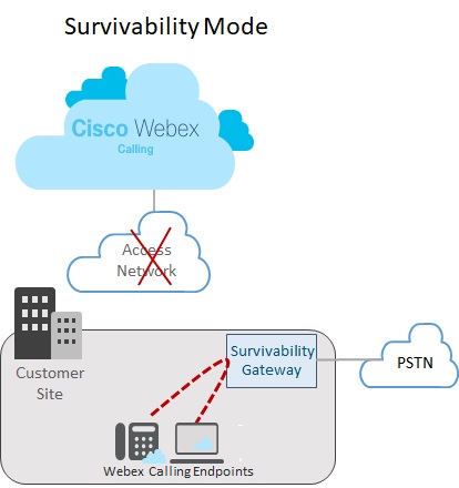
次の画像は、Webexへの接続が切断され、Webexサイトのエンドポイントがサバイバビリティモードで動作しているネットワーク障害のシナリオを示しています。この図では、サバイバビリティゲートウェイがWebexへの接続を必要とせずに、2つのオンサイトエンドポイント間で内部通話をルーティングしている様子が示されています。この場合、サバイバビリティゲートウェイはローカルPSTN接続で構成されます。その結果、サバイバビリティモードのオンプレミス端末は、外部番号やE911プロバイダーへの着信および発信にPSTNを利用できるようになります。
複数拠点設定
以下の画像は、Webexへの接続が切断され、異なる場所に設置されたエンドポイントがサバイバビリティモードで動作しているネットワーク障害のシナリオを示しています。LANネットワーク内には、単一のサバイバビリティゲートウェイにマッピングされた複数の小規模な拠点が存在する。この導入により、ゲートウェイのリソース利用効率が最適化されるとともに、通話ルーティングに関する地域固有の設定が維持されます。
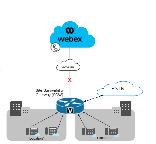
Ciscoは、LAN内の複数の拠点間におけるサバイバビリティゲートウェイとエンドポイント間の接続において、遅延時間を50ミリ秒以下に維持することを推奨しています。
サイトの存続可能性に関する重要な条件
サバイバビリティゲートウェイには、以下の条件が適用されます。
-
Webexクラウドでは、デバイス構成ファイルにサバイバビリティゲートウェイのIPアドレス、ホスト名、ポート番号が含まれています。その結果、エンドポイントはWebexへの接続が切断された場合でも、登録のためにサバイバビリティゲートウェイにアクセスできるようになります。
-
Webexクラウドとサバイバビリティゲートウェイ間の毎日の通話データ同期には、登録ユーザーの認証情報が含まれます。その結果、エンドポイントは、サバイバビリティモードで動作している場合でも、安全な登録を維持できる。同期には、これらのユーザーのルーティング情報も含まれます。
-
サバイバビリティゲートウェイは、Webexが提供するルーティング情報を使用して、内部通話を自動的にルーティングできます。外部通話機能を提供するために、サバイバビリティゲートウェイにPSTNトランク構成を追加します。
-
サイトサバイバビリティを導入する各サイトは、ローカルネットワーク内にサバイバビリティゲートウェイを設置する必要があります。
-
Webexネットワーク接続が少なくとも30秒間復旧すると、登録と通話制御の両方がWebexクラウドに切り替わります。
Unified SRSTとのコロケーション
サバイバビリティゲートウェイは、Webexサバイバビリティ構成と統合SRST構成を同じゲートウェイ上に共存させることをサポートします。このゲートウェイは、Webex Callingエンドポイントと、Unified Communications Managerに登録するエンドポイントの両方に対して、可用性をサポートできます。コロケーションを設定するには:
-
Unified Communications Managerに登録するエンドポイントに対して、Unified SRSTのサポートを設定します。設定については、 Cisco Unified SRST 管理ガイドを参照してください。
-
同じゲートウェイで、この記事の サイトサバイバビリティ構成タスクフロー に従って、Webex Calling エンドポイントのサイトサバイバビリティを使用してゲートウェイを構成します。
コロケーションにおける通話ルーティングに関する考慮事項
コロケーションシナリオにおける通話ルーティングの設定にあたっては、以下の点を考慮してください。
-
サバイバビリティゲートウェイは、通話の両端のエンドポイントがサバイバビリティゲートウェイに登録されている場合、内部通話を自動的にルーティングします。内部通話は、登録済みのクライアント(SRSTまたはWebex Calling)間で自動的にルーティングされます。
-
一方の通話制御システムへの接続が切断されても、もう一方の通話制御システムへの接続は維持されるという状況が発生する可能性があります。その結果、一方のエンドポイント群はサバイバビリティゲートウェイに登録され、同じサイト内のもう一方のエンドポイント群はプライマリコール制御に登録される。この場合、2つのエンドポイント間の通話をSIPトランクまたはPSTN回線にルーティングする必要があるかもしれません。
-
外部通話およびE911通話は、SIPトランクまたはPSTN回線にルーティングできます。
サポートされている機能とコンポーネント
以下の表は、サポートされている機能に関する情報を示しています。
| 機能 | MPPデバイスとWebexアプリ | VG4xx ATA |
|---|---|---|
|
サイト内拡張呼び出し |
サバイバビリティゲートウェイでは、特別なルーティング設定は不要で、自動的にサポートされます。 |
サバイバビリティゲートウェイでは、特別なルーティング設定は不要で、自動的にサポートされます。 代替番号はサポートされていません。 |
|
サイト間通話およびPSTN通話(着信および発信) |
通信事業者の回線またはSIPトランクに基づくPSTN通話。 |
通信事業者の回線またはSIPトランクに基づくPSTN通話。 |
|
E911通報対応 |
E911通報にはPSTN回線またはSIPトランクが必要です。 発信通話では、特定の緊急対応拠点(ERL)に対応する、登録済みの緊急拠点識別番号(ELIN)が使用されます。緊急オペレーターが切断された通話に折り返し連絡した場合、サバイバビリティゲートウェイは、その通話を緊急番号に最後に電話をかけたデバイスに転送します。 |
E911通報にはPSTN回線またはSIPトランクが必要です。 発信通話では、特定の緊急対応拠点(ERL)に対応する、登録済みの緊急拠点識別番号(ELIN)が使用されます。緊急オペレーターが切断された通話に折り返し連絡した場合、サバイバビリティゲートウェイは、その通話を緊急番号に最後に電話をかけたデバイスに転送します。 |
|
通話の保留と再起動 |
サポートあり 保留音(MOH)を使用している場合は、MOHファイルを使用してサバイバビリティゲートウェイを手動でプロビジョニングしてください。 |
VG4xx ATA アナログ回線では、通話を保留または再開することはできません。 この機能は、VG4xx ATA で着信があった場合にのみサポートされます。 |
|
通話転送 |
サポートあり |
この機能は、VG4xx ATA で着信があった場合にのみサポートされます。 |
|
ブラインドコール転送 |
サポートあり |
この機能は、VG4xx ATA で着信があった場合にのみサポートされます。 |
|
着信発信者 ID (名前) |
対応あり |
対応あり |
|
着信発信者番号(名前) & 番号) |
対応あり |
対応あり |
|
ポイントツーポイントのビデオ通話 |
対応あり |
対応なし |
|
三者通話 |
対応なし |
対応なし |
|
共有回線 |
対応あり |
対応あり |
|
仮想回線 |
対応あり |
対応なし |
|
通話転送 |
全着信転送、応答なし、通話中に対応しています。 |
サポートあり |
|
ハントグループ |
以下の製品がサポートされています。シーケンシャル、パラレル、ピア、および最長アイドル時間。 |
サポートあり |
|
自動音声応答 |
内線によるダイヤルに対応 |
サポートあり |
この機能を設定すると、以下のサポート対象エンドポイントでサイトサバイバビリティが利用可能になります。
| タイプ | モデル | 最小バージョン |
|---|---|---|
| マルチプラットフォーム(MPP)ファームウェア搭載のCisco IP電話 |
6821、6841、6851、6861、6861 Wi-Fi、6871 7811, 7821, 7841, 7861 8811, 8841, 8851, 8861 8845(音声のみ)、8865(音声のみ)、8875(映像) 9800 マルチプラットフォーム(MPP)ファームウェアを搭載したCisco IP電話のサポート対象製品に関する詳細は、以下を参照してください。 |
12.0(1) 8875搭載端末の場合 - Phone OS 3.2以降のバージョン 9800シリーズ向け - PhoneOS 3.2(1) |
|
Cisco IP Conference Phone |
7832, 8832 |
12.0(1) |
|
Cisco Webex アプリ |
Windows、Mac |
43.2 |
|
アナログエンドポイント |
VG400 ATA、VG410 ATA、VG420 ATA Cisco ATA 191 および 192 |
17.16.1a 11.3(1) ATA 191および192について |
Survivability Gatewayでは、サードパーティ製デバイスはサポートされていません。
以下の表は、Cisco IOS XEルータをサバイバビリティゲートウェイとして設定する際に役立ちます。この表は、各プラットフォームがサポートするエンドポイントの最大数と、最小のIOS XEバージョンを示しています。
Webex Calling Survivability Gatewayの機能は、Cisco IOS XE Dublin 17.12.3以降のバージョンで利用可能です。ハントグループ、着信転送、自動応答機能は、iOS 17.18.2以降のバージョンで利用可能です。
| モデル | 最大エンドポイント登録数 | 最小バージョン |
|---|---|---|
|
統合サービスルーター4321 | 50 |
Cisco IOS XE Dublin 17.12.3以降のリリース |
|
統合サービスルーター4331 | 100 | |
|
統合サービスルーター4351 | 700 | |
|
統合サービスルーター4431 | 1200 | |
|
統合サービスルーター4451-X | 2000 | |
|
統合サービスルーター4461 | 2000 | |
|
Catalyst Edge 8200L-1N-4T | 1500 | |
|
Catalyst Edge 8200-1N-4T | 2500 | |
|
Catalyst Edge 8300-1N1S-6T | 2500 | |
|
Catalyst Edge 8300-2N2S-6T | 2500 | |
|
Catalyst Edge 8300-1N1S-4T2X | 2500 | |
|
Catalyst Edge 8300-2N2S-4T2X | 2500 | |
|
Catalyst Edge 8000V ソフトウェアの小規模構成 | 500 | |
|
Catalyst Edge 8000V ソフトウェアの中間構成 | 1000 | |
|
Catalyst Edge 8000V ソフトウェア大規模構成 | 2000 |
サバイバビリティゲートウェイのポート参照情報
|
接続目的 |
ソース アドレス |
ソース ポート |
プロトコル |
接続先アドレス |
宛先ポート |
|---|---|---|---|---|---|
|
サバイバビリティゲートウェイへのコールシグナリング(SIP TLS) |
デバイス |
5060-5080 |
TLS |
サバイバビリティ ゲートウェイ |
8933 |
|
報道関係者はサバイバビリティ・ゲートウェイ(SRTP)までご連絡ください。 |
デバイス |
19560-19660 |
UDP |
サバイバビリティ ゲートウェイ |
8000-14198 (UDP上のSRTP) |
|
PSTNゲートウェイへの通話シグナリング(SIP) |
サバイバビリティ ゲートウェイ |
一時的 |
TCPまたはUDP |
ITSP PSTNゲートウェイ |
5060 |
|
PSTN ゲートウェイへのコール メディア (SRTP) |
サバイバビリティ ゲートウェイ |
8000-48198 |
UDP |
ITSP PSTNゲートウェイ |
一時的 |
|
時刻同期(NTP) |
サバイバビリティ ゲートウェイ |
一時的 |
UDP |
NTPサーバー |
123 |
|
名前解決(DNS) |
サバイバビリティ ゲートウェイ |
一時的 |
UDP |
DNSサーバー |
53 |
|
クラウド管理 |
コネクタ |
一時的 |
HTTPS |
Webex サービス |
443, 8433 |
クラウドモードの操作手順については、 Webex Calling のポート参照情報 ヘルプ記事を参照してください。
Cisco IOS XEルータでは、ポート設定値をカスタマイズできます。この表は、参考値としてデフォルト値を使用しています。
機能設定
サイトの耐障害性構成タスクフロー
既存のWebex Callingロケーションにサイトサバイバビリティを追加するには、以下のタスクを完了してください。Webexクラウドへの接続が切断された場合、ローカルネットワーク内のサバイバビリティゲートウェイが、その場所にあるエンドポイントに対してバックアップの通話制御を提供できます。
開始する前に
サバイバビリティ ゲートウェイとして機能する新しいゲートウェイをプロビジョニングする必要がある場合は、Webex の記事 Cisco IOS マネージド ゲートウェイを Webex Cloud に登録する を参照して、ゲートウェイをコントロール ハブに追加してください。
| ステップ | コマンドまたはアクション | 目的 |
|---|---|---|
|
1 | ゲートウェイに生存性サービスを割り当てる |
コントロール ハブで、 サバイバビリティ ゲートウェイ サービスをゲートウェイに割り当てます。 |
|
2 | 構成テンプレートをダウンロード |
コントロールハブから設定テンプレートをダウンロードしてください。ゲートウェイのコマンドラインを設定する際には、テンプレートが必要になります。 |
|
3 |
サバイバビリティゲートウェイのライセンスを設定します。 | |
|
4 |
サバイバビリティゲートウェイ用の証明書を設定します。 | |
|
5 |
以前ダウンロードした設定テンプレートを参考に、ゲートウェイのコマンドラインを設定してください。テンプレートに記載されている必須設定をすべて完了してください。 |
ゲートウェイに生存性サービスを割り当てる
開始する前に
| 1 |
サービスの下にある呼び出し[]に移動し、 管理ゲートウェイ タブをクリックします。 「管理対象ゲートウェイ」ビューには、Control Hub を通じて管理しているゲートウェイの一覧が表示されます。
|
| 2 |
サバイバビリティゲートウェイとして割り当てるゲートウェイを選択し、 Service フィールドの値に基づいて、以下のいずれかを選択してください。
|
| 3 |
サービスタイプのドロップダウンリストから サバイバビリティゲートウェイ を選択し、以下のフィールドに入力してください。
登録が完了すると、管理対象ゲートウェイのページに場所の詳細が表示されます。 |
| 4 |
[指定] をクリックします。 「管理対象ゲートウェイ」ビューには、ゲートウェイに割り当てられている場所のリストが表示されます。
|
構成テンプレートをダウンロード
| 1 |
パートナー組織の方は、パートナーハブが利用可能になります。コントロール ハブを開くには、パートナー ハブの 顧客 ビューをクリックして該当する顧客を選択するか、 マイ組織 を選択してパートナー組織のコントロール ハブ設定を開きます。 |
| 2 |
。 |
| 3 |
該当するサバイバビリティゲートウェイをクリックしてください。 |
| 4 |
設定テンプレートをダウンロード をクリックして、テンプレートをデスクトップまたはノートパソコンにダウンロードしてください。 |
ライセンスの設定
| 1 |
ルーターでグローバル設定モードに入ります。 |
| 2 |
ご使用のプラットフォームにのみ適用されるコマンドを使用して、ライセンスを設定してください。
スループットを250Mbps以上に設定する場合は、HSECプラットフォームライセンスが必要です。 |
証明書の設定
Cisco IOS XEで証明書を設定する
サバイバビリティゲートウェイの証明書を要求および作成するには、以下の手順を実行してください。公的に認知されている認証局によって署名された証明書を使用してください。
Survivability Gatewayプラットフォームは、一般に公開されている認証局(CA)証明書のみをサポートしています。プライベートまたはエンタープライズの認証局証明書は、サバイバビリティゲートウェイには使用できません。
Webex Calling でサポートされているルート証明機関のリストについては、 Cisco Webex Audio および Video プラットフォームへの通話でサポートされているルート証明機関はどれですか?を参照してください。
Survivability Gatewayプラットフォームは、ワイルドカード証明書をサポートしていません。
サンプルコードに含まれるコマンドを実行して、手順を完了してください。これらのコマンドの詳細とその他の設定オプションについては、 Cisco Unified Border Element Configuration Guideの「 SIP TLS サポート]」の章を参照してください。
| 1 |
以下のコマンドを実行して、グローバル設定モードに入ります。 |
| 2 |
以下のコマンドを実行して、RSA秘密鍵を生成します。秘密鍵のモジュラスは、少なくとも2048ビットでなければなりません。 |
| 3 |
サバイバビリティゲートウェイ証明書を保持するトラストポイントを設定します。ゲートウェイの完全修飾ドメイン名(FQDN)には、ゲートウェイにサバイバビリティサービスを割り当てた際に使用した値と同じ値を使用する必要があります。 |
| 4 |
プロンプトが表示されたら、 CSRが画面に表示されたら、メモ帳を使って証明書をファイルにコピーし、サポートされている認証局(CA)に送信してください。 証明書署名プロバイダーがPEM(プライバシー強化メール)形式のCSRを要求する場合は、送信前にヘッダーとフッターを追加してください。例: |
| 5 |
CAが証明書を発行したら、 プロンプトが表示されたら、base64 を貼り付けます CER/PEM 端末にCA証明書の内容(デバイス証明書ではない)を発行する。 |
| 6 |
プロンプトが表示されたら、base64 を貼り付けます CER/PEM 証明書を端末に入力してください。 |
| 7 |
ルートCA証明書が利用可能であることを確認してください。 Webex Callingソリューションでは、一般に公開されている認証局のみがサポートされています。プライベートまたはエンタープライズCA証明書はサポートされていません。 |
| 8 |
ルートCA証明書がバンドルに含まれていない場合は、証明書を取得して新しいトラストポイントにインポートしてください。 Cisco IOS XEゲートウェイに公開されているCAルート証明書がない場合は、この手順を実行してください。 プロンプトが表示されたら、base64 を貼り付けます CER/PEM 証明書の内容を端末に入力してください。 |
| 9 |
設定モードを使用して、以下のコマンドでデフォルトのトラストポイント、TLSバージョン、およびSIP-UAのデフォルト値を指定します。 |
証明書とキーペアをインポートする
CA証明書とキーペアは、PKCS12形式(.pfxまたは.p12)を使用してバンドルとしてインポートできます。ローカルファイルシステムまたはリモートサーバーからバンドルをインポートできます。PKCS12は、特殊な証明書フォーマットの一種です。これは、ルート証明書からID証明書までの証明書チェーン全体と、RSAキーペアをまとめて提供します。つまり、インポートするPKCS12バンドルには、キーペア、ホスト証明書、および中間証明書が含まれます。以下のシナリオに対応するPKCS12バンドルをインポートします。
-
別のCisco IOS XEルータからエクスポートし、サバイバビリティゲートウェイルータにインポートします。
-
Cisco IOS XEルータ外部でOpenSSLを使用してPKCS12バンドルを生成する
サバイバビリティゲートウェイルーター用の証明書とキーペアを作成、エクスポート、インポートするには、以下の手順を実行してください。
| 1 |
(オプション)サバイバビリティゲートウェイルーターに必要なPKCS12バンドルをエクスポートします。 この手順は、別のCisco IOS XEルータからエクスポートする場合にのみ適用されます。 |
| 2 |
(オプション)OpenSSLを使用してPKCS12バンドルを作成します。 この手順は、OpenSSLを使用してCisco IOS XEの外部でPKCS12バンドルを生成する場合にのみ適用されます。 |
| 3 |
PKCS12形式のファイルバンドルをインポートします。 以下は、コマンドの設定例と、設定可能なパラメータに関する詳細です。
crypto pki import コマンドは、証明書に対応するトラストポイントを自動的に構築します。 |
| 4 |
設定モードを使用して、以下のコマンドでデフォルトのトラストポイント、TLSバージョン、およびSIP-UAのデフォルト値を指定します。 |
サバイバビリティゲートウェイの設定
ゲートウェイをサバイバビリティゲートウェイとして構成する
以前ダウンロードした設定テンプレートを参考に、ゲートウェイのコマンドラインを設定してください。テンプレートに記載されている必須設定をすべて完了してください。
以下の手順には、コマンド例とそれぞれの説明が含まれています。設定を環境に合わせて編集してください。山括弧(例: <settings>)は、デプロイメントに適用される値を入力する必要がある設定を示します。さまざまな <tag> 設定は、数値を使用して構成のセットを識別および割り当てます。
- 特に明記されていない限り、このソリューションでは、この手順に記載されているすべての設定を完了する必要があります。
- テンプレートから設定を適用する場合は、ゲートウェイにコピーする前に、
%tokens%を希望の値に置き換えてください。 - コマンドの詳細については、 Webex Managed Gateway コマンド リファレンスを参照してください。コマンドの説明で別のドキュメントを参照するように指示されていない限り、このガイドを使用してください。
| 1 |
グローバル設定モードに入ります。 意味:
|
| 2 |
音声サービスの設定を実行します。
コマンドの説明:
|
| 3 |
ルーターでサバイバビリティを有効にする: コマンドの説明:
|
| 4 |
NTPサーバーの設定:
|
| 5 |
(任意)一般的な制限クラスの呼び出し権限を設定します。 上記の例では、カテゴリ(例: |
| 6 |
優先コーデックのリストを設定します。例えば、以下のリストでは、優先コーデックとしてg711ulawが指定され、続いてg711alawが指定されています。 コマンドの説明:
|
| 7 |
デフォルトの音声レジスタプールを設定する: コマンドの説明:
|
| 8 |
緊急通報の設定: コマンドの説明:
Wi-FiオーバーレイがIPサブネットに正確に一致しない場合、モバイルデバイスからの緊急通報において、正しいELINマッピングが適用されない可能性があります。 |
| 9 |
PSTNのダイヤルピアを設定します。ダイヤルピア構成の例については、 PSTN接続例を参照してください。 |
| 10 |
オプションです。ルーターで保留音を有効にする。音楽ファイルは、G.711形式でルーターのフラッシュメモリに保存する必要があります。ファイルは.auまたは.wavファイル形式でも構いませんが、ファイル形式には8ビット8kHzのデータが含まれている必要があります(例えば、ITU-T A則またはμ則データ形式)。 コマンドの説明:
|
完全オンデマンド同期
オプションです。即時のオンデマンド同期を実行したい場合にのみ、この手順を実行してください。この手順は必須ではありません。Webexクラウドは、通話データを1日1回、自動的にサバイバビリティゲートウェイに同期します。
| 1 |
パートナー組織の方は、パートナーハブが利用可能になります。コントロール ハブを開くには、パートナー ハブの 顧客 ビューをクリックして該当する顧客を選択するか、 マイ組織 を選択してパートナー組織のコントロール ハブ設定を開きます。 |
| 2 |
。 |
| 3 |
該当するサバイバビリティゲートウェイをクリックすると、そのゲートウェイの サバイバ ビリティサービスビューが開きます。 |
| 4 |
同期 ボタンをクリックしてください。 |
| 5 |
[送信] をクリックします。 同期が完了するまで最大10分かかる場合があります。
|
サバイバビリティゲートウェイのプロパティを編集します
| 1 |
パートナー組織の方は、パートナーハブが利用可能になります。コントロール ハブを開くには、パートナー ハブの 顧客 ビューをクリックして該当する顧客を選択するか、 マイ組織 を選択してパートナー組織のコントロール ハブ設定を開きます。 |
| 2 |
。 |
| 3 |
該当するサバイバビリティゲートウェイをクリックすると、そのゲートウェイの サバイバ ビリティサービスビューが開きます。 |
| 4 |
編集 ボタンをクリックして、以下の設定を更新してください。
|
| 5 |
[送信] をクリックします。 コントロール ハブからサバイバビリティ ゲートウェイを削除する場合は、まず サバイバビリティ ゲートウェイ サービスの割り当てを解除してください。詳細については、 マネージドゲートウェイへのサービスの割り当てを参照してください。 |
サバイバビリティゲートウェイでCDRを有効にするための設定
コネクタは、通話件数メトリクスの収集を容易にするために、CDR関連のコマンドを自動的に構成します。
生存性イベントの終了時に、コネクタはイベント期間中に生成されたCDRと構成データを処理し、さまざまな通話回数を識別します。これらの指標には、総通話数、緊急通話数、外部通話数が含まれ、内部機能の使用状況を監視するために使用されます。通話件数の指標のみがWebexクラウドに送信され、実際の通話記録(CDR)は送信されません。
以下は設定例です。
!
gw-accounting file
primary ifs bootflash:guest-share/cdrs/
acct-template callhistory-detail
maximum cdrflush-timer 5
cdr-format detailed
!
コマンドの説明:
-
primary ifs bootflash:guest-share/cdrs/- このコマンドは、コネクタがアクセスできるように、CDRファイルをゲスト共有フォルダに保存するためのものです。 -
acct-template callhistory-detail- このコマンドは、CDRにダイヤルピアタグを含めるために必要です。 -
maximum cdrflush-timer 5デフォルトは60分ですが、5分に設定すると、CDRをより迅速にファイルに記録できます。 -
cdr-format detailed- これはデフォルトのフォーマットです。コンパクト形式はダイヤルピアタグが含まれていないため、適していません。
通話転送を有効にするための設定
通話転送機能は、Webexクラウドへの接続が失われたネットワーク障害時にも通話処理を継続できるようにする、耐障害性機能の一部です。サバイバビリティゲートウェイはローカルフォールバックゲートウェイとして機能し、エンドポイントがローカルに登録して基本的な通話機能を維持できるようにします。
-
サバイバビリティモードにおける通話転送動作は、サバイバビリティゲートウェイによって管理され、プール構成、ダイヤルピア構成、および通話をローカルで処理するか、PSTNまたはSIPトランク経由でルーティングするルーティングポリシーが使用されます。
-
サバイバビリティゲートウェイは、SIP REFER、SIPの一時的な通話転送および通話転送補助サービスを無効にします。これは、Webex Callingがサバイバビリティモードではこれらの方法を使用しないためです。
着信転送シナリオ向けに音声登録プールを設定する:
|
着信転送機能を使用するには、各電話機の
|
ハントグループを有効にするための設定
この表は、Control Hub でのハントグループ機能構成と、サバイバビリティゲートウェイコマンドの使用に関するマッピングを示しています。
| ハントグループの特徴 | コントロールハブを使用した設定 | 生存性ゲートウェイコマンド |
|---|---|---|
|
通話ルーティングパターンを選択してください |
Top-Down/Simultaneous/Circular/Longest-idle | Sequential/Parallel/Peer/Longest-idle |
|
ハントグループを追加する |
各場所ごとに、ハント グループ名と電話番号を追加してください。 | ハントグループを追加するには、 voice hunt-group を使用します。次に、 pilot コマンドを使用して電話番号を追加し、 description コマンドを使用してハントグループ名を追加します。 |
|
追加するユーザー、ワークスペース、または仮想回線を選択してください |
ハントグループの一員となるエージェントを選択してください |
|
|
設定された回数の呼び出しの後に進む |
リング数の設定 オプションを使用して設定します |
|
|
取り込み中に進む |
ビジー時に進める オプションを使用して設定します |
|
|
どのエージェントにもつながらない場合に通話を迂回 | すべてのエージェントに到達できない場合にコールを転送する オプションを使用して設定します |
|
|
すべてのエージェントが取り込み中か、ハント グループが取り込み中である場合に通話を転送 |
すべてのエージェントがビジー状態、またはハントグループがビジー状態のときにコールを転送する オプションを使用して設定します。 |
設定方法 |
-
ハントグループのシーケンシャルリングを設定する
voice hunt-group 1 sequential pilot 1111 number 1 1001 number 2 1002 number 3 7089001 number 4 7089002 number 5 +1210903443 ..... ..... timeout 20 final 1009 statistics collect description present-call idle-phone -
ハントグループの並列リングを構成する
voice hunt-group 2 parallel pilot 2222 number 1 2001 number 2 2002 number 3 2089001 number 4 2089002 number 5 +12109034433 ..... ..... timeout 60 final 1009 statistics collect description
コマンドの説明:
-
voice hunt-group- このコマンドは、ハントグループの設定モードを定義し、そのモードに入るために使用されます。 -
parallel- このキーワードは、システムが着信コールをこのハントグループのメンバー間で分配するために使用するハントグループ方式またはアルゴリズムを指定します。 -
number- リストを作成します extensions/e164 numbers/ESN 彼らは声探しグループのメンバーである。リスト内の番号は、他のハント グループのパイロット番号であってはならない。 -
pilotこれはハント グループの代表番号、または内線番号です。ハント グループに連絡するには、この番号にダイヤルしてください。 -
timeout- ハント グループが次の行動を起こす前にメンバーに連絡を試みる最大時間を秒単位で設定します。 -
final- このコマンドはフォールバック番号を指定します。 -
statistics collect- ハント グループの運用統計情報の収集を可能にします。 -
descriptin- ハント グループの説明 -
present-call idle-phone-待機中のエージェントにのみ通話を転送する。
以下は、 show voice hunt-group statistics コマンドの出力例です。出力には、音声ハントグループ番号への直接通話と、キューまたはB-ACDからの通話が含まれます。
Router# show voice hunt-group 1 statistics last 1 h
Wed 04:00 - 05:00
Max Agents: 3
Min Agents: 3
Total Calls: 9
Answered Calls: 7
Abandoned Calls: 2
Average Time to Answer (secs): 6
Longest Time to Answer (secs): 13
Average Time in Call (secs): 75
Longest Time in Call (secs): 161
Average Time before Abandon (secs): 8
Calls on Hold: 2
Average Time in Hold (secs): 16
Longest Time in Hold (secs): 21
Per agent statistics:
Agent: 5012
From Direct Call:
Total Calls Answered: 3
Average Time in Call (secs): 70
Longest Time in Call (secs): 150
Totals Calls on Hold: 1
Average Hold Time (secs): 21
Longest Hold Time (secs): 21
From Queue:
Total Calls Answered: 3
Average Time in Call (secs): 55
Longest Time in Call (secs): 78
Total Calls on Hold: 2
Average Hold Time (secs): 19
Longest Hold Time (secs): 26
Total Loged in Time (secs): 3000
Total Loged out Time (secs): 600
Agent: 5013
From Direct Call:
Total Calls Answered: 3
Average Time in Call (secs): 51
Longest Time in Call (secs): 118
Totals Calls on Hold: 1
Average Hold Time (secs): 11
Longest Hold Time (secs): 11
From Queue:
Total Calls Answered: 1
Average Time in Call (secs): 4
Longest Time in Call (secs): 4
Total Loged in Time (secs): 3000
Total Loged out Time (secs): 600
Agent: 5014
From Direct Call:
Total Calls Answered: 1
Average Time in Call (secs): 161
Longest Time in Call (secs): 161
From Queue:
Total Calls Answered: 1
Average Time in Call (secs): 658
Longest Time in Call (secs): 658
Total Loged in Time (secs): 3000
Total Loged out Time (secs): 600
Queue related statistics:
Total calls presented to the queue: 5
Calls handoff to IOS: 5
Number of calls in the queue: 0
Average time to handoff (secs): 2
Longest time to handoff (secs): 3
Number of abandoned calls: 0
Average time before abandon (secs): 0
Calls forwarded to voice mail: 0
Calls answered by voice mail: 0
Number of error calls: 0
Router# sh voice hunt-group
Group 1
type: sequential
pilot number: 4444, peer-tag 2147483647
list of numbers:
Member Used-by State Login/Logout
====== ======= ===== ============
1001 1001 up -
1003 1003 up -
preference: 0
preference (sec): 0
timeout: 15
final_number:
auto logout: no
stat collect: no
phone-display: no
hlog-block: no
calls in queue: 0
overwrite-dyn-stats: no
members logout: no
present-call idle-phone: no
webex-sgw-bgl14#
基本自動着信分配(B-ACD)を有効にするための設定
基本自動着信分配(B-ACD)および自動応答(AA)サービスは、外部からの着信に自動的に応答し、挨拶とメニューを提供することで、発信者が適切な部署を選択したり、既知の内線番号にダイヤルしたりできるようにします。
B-ACDは、対話型メニューとローカルハントグループを使用して、着信に対する自動応答と着信分配機能を提供します。B-ACDアプリケーションは、自動応答(AA)サービスと1つのコールキューサービスで構成されています。B-ACD自動応答システムは、g711ulawコーデックを使用した着信SIPトランクとネゴシエートされたPSTN通話をサポートします。
B-ACDは、シーケンシャル、パラレル、ピア、最長アイドルコールブラストによる音声ハントグループをサポートし、SIP共有回線および混合共有回線をサポートします。
着信があると、B-ACD AAのパイロット番号にダイヤルされ、挨拶と指示が流れる音声ガイダンスが流れ、発信者が通話を自動的にルーティングできるようになります。
制限
通話転送時には、着信側と発信側のダイヤルピアで同じコーデックを使用してください。異なるコーデックの使用はサポートされていません。IOSは、TCLアプリケーションによって処理される通話に対してトランスコーダーを起動しません。
B-ACDコンポーネント
B-ACDアプリケーションは、コールキューサービスと1つ以上のAAサービスで構成されます。これらのサービスの構成可能なコンポーネントは以下のとおりです。
-
パイロット番号
-
ウェルカムプロンプトおよびその他の音声ファイル
-
メニューオプション
-
内線番号でダイヤルする
パイロット番号
AAの各サービスには、AAに連絡するために発信者がダイヤルする専用のAAパイロット番号があります。この数値は param aa-pilot コマンドで指定されます。AAパイロット番号は、エージェントの電話番号や物理的な電話機とは関連付けられていませんが、外部からの発信者がこの番号にアクセスできるように、AAパイロット番号を着信番号としてダイヤルピアを定義する必要があります。
ウェルカムプロンプトおよびその他の音声ファイル
ウェルカムプロンプトとは、パイロット番号で電話に出た際に再生される音声ファイルのことです。この音声ファイルは、B-ACDサービスで使用される複数の音声ファイルのうちの1つで、発信者に状況や取るべき行動を知らせるために使用されます。発信者が利用できるメニュー選択肢を説明する、パーソナライズされた音声ファイルを作成できます。B-ACDオーディオファイルについては、以下のセクションで説明します。
デフォルトのオーディオファイルを再録音しています
スクリプトの各箇所にはデフォルトの音声ファイルが用意されており、発信者に提供されます。 リンク からデフォルトのオーディオファイルをダウンロードし、フラッシュメモリやTFTPサーバーなど、B-ACDルーターからアクセスできる場所にコピーします。音声ファイルとスクリプトファイルは、ウェブサイト上のtarファイルにまとめられています。デフォルトのファイルとそのメッセージは表に記載されています。デフォルトのメッセージに上書きしてパーソナライズされたメッセージを再録音することはできますが、 言語コードとファイル名の変更に具体的に記載されている場合を除き、音声ファイルの名前を変更することはできません。
B-ACD サービスを初めて使用する前に、デフォルトの音声プロンプトを再録音してインストールするには、 Tcl スクリプトと音声プロンプトのダウンロードの手順に従ってください。既存の B-ACD サービスで音声プロンプトを再録音するには、 スクリプト パラメーターと音声プロンプトの更新 (内線によるダイヤルのみ)の手順に従ってください。
| デフォルトのファイル名 | デフォルトのアナウンス | デフォルト通知の長さ |
|---|---|---|
en_bacd_welcome.au |
"お電話頂きありがとうございます。" メッセージの後には2秒間の間隔があります。 |
3秒 |
en_bacd_options_menu.au |
販売に関するお問い合わせは1番を押してください(一時停止) カスタマーサービスへは2番を押してください(一時停止) 内線番号でダイヤルするには、3を押してください(一時停止)。 オペレーターと話すには、ゼロを押してください。 メッセージの後には4秒間の間隔があります。 |
15seconds |
en_bacd_disconnect.au |
「現在、お電話をお受けすることができません。」時間をおいて再試行してください。お電話頂きありがとうございます。" メッセージの後には4秒間の間隔があります。 |
10seconds |
en_bacd_invalidoption. au |
「無効なオプションを入力しました。」もう一度お試しください。メッセージの後に1秒間の間隔を設けます。この音声ガイダンスは、発信者が無効なメニューオプションを選択した場合、または無効な内線番号をダイヤルした場合に再生されます。 |
7seconds |
en_bacd_enter_dest.au |
「連絡を取りたい内線番号を入力してください。」メッセージの後には5秒間の間隔があります。このプロンプトは、発信者が |
7seconds |
en_bacd_allagentsbusy. au |
「現在、すべての担当者が他のお客様の対応で忙しくしております。」引き続き支援をお待ちください。まもなく担当者が伺います。メッセージの後には2秒間の間隔があります。このプロンプトは、2番目の挨拶とも呼ばれます。 |
7seconds |
en_bacd_music_on_hol d.au |
B-ACD回線を使用している発信者には、保留音(MOH)が再生されます。 |
60seconds |
音声ファイルを再録音する場合は、B-ACDのプロンプトには、8ビット、μ-law、8kHzのエンコーディングを備えたG.711オーディオファイル(.au)形式が必要であることに注意してください。以下のオーディオツール、または同等の品質のその他のツールをお勧めします。
-
Adobe Systems Inc.製のMicrosoft Windows版Adobe Audition(旧称:Syntrillium Software Corp.製のCool Edit)
-
Sun Microsystems Inc.製のSolaris用AudioTool
B-ACDの設定
以下にいくつかの設定例を示します。
application
service aa bootflash:app-b-acd-aa-3.0.0.8.tcl
paramspace english index 1
param handoff-string aa
param dial-by-extension-option
paramspace english language en
param aa-pilot
paramspace english location flash:
param welcome-prompt _bacd_welcome.au
param voice-mail
param service-name queue
!
service queue bootflash:app-b-acd-3.0.0.8.tcl
param queue-len 30
param queue-manager-debugs 1
!
! SIP PSTN Dial-Peers for Auto Attendant(BACD) service called aa associated with incoming voice port
dial-peer voice 500 voip
description Inbound dial-peer for Auto Attendant
service aa
session protocol sipv2
incoming called-number
dtmf-relay rtp-nte
codec g711ulaw
no vad
!
! TDM PSTN Dial-Peers if not using SIP for Auto Attendant(BACD) service called aa associated with incoming voice pots
dial-peer voice 500 voip
description Inbound dial-peer for Auto Attendant
service aa
incoming called-number
port %tdm_port%
! | コマンド | 説明 |
|---|---|
param dial-by-extension-option |
指定されたメニュー番号をダイヤルした後、発信者が内線番号をダイヤルできるようにします。 メニュー番号—メニューオプションの識別子。範囲は1から9までです。デフォルト設定はありません。 |
param aa-pilot |
自動応答ダイヤルピアに関連付けられたパイロット番号を指定します |
param voice-mail |
AAのエージェントが応答しない通話の代替転送先を定義します。 |
paramspace english language en |
IVRアプリケーションによる動的プロンプトに使用される音声ファイルの言語コードを定義します。
この言語コードは、ファイル内で実際に使用されている言語に関係なく、音声プロンプトファイルの名前に使用されている2文字の言語接頭辞と一致している必要があります。詳細については、 ウェルカムプロンプトとその他の音声ファイルを参照してください。 |
param welcome-prompt
audio-filename |
このAAサービスで使用される歓迎挨拶用の音声ファイルを割り当てます。
|
言語コードとファイル名の変更
-
ファイル名の接頭辞は、ch、en、sp、またはaaに変更できます。プレフィックスは、ファイル内で実際に使用されている言語に関係なく、paramspace language コマンドの language-code パラメータで指定されているコードと一致していなければなりません。
-
プレフィックスに続くウェルカムプロンプトファイル名(デフォルトは en_bacd_welcome.au)には、
param welcome-promptコマンドで定義されている任意の識別名を付けることができます。 -
プレフィックスに続くドロップスループロンプトファイル名(デフォルト値は指定されていません)には、
param drop-through-promptコマンドで定義されている任意の識別名を付けることができます。
音声ファイルには、任意の言語でプロンプトを録音できます。異なる言語のプロンプトを含むファイルのプレフィックスを変更する必要はありません。なぜなら、言語コードのプレフィックスは、B-ACD サービスの一部ではない機能に使用されるからです。しかし、オーディオファイルで実際に使用されている言語に関係なく、ファイルの言語コード接頭辞が、paramspace languageコマンドのlanguage-codeパラメータで指定されている言語コードと一致していることが重要です。
_bacd_welcome.au ファイルを除き、音声ファイルの名前の識別子部分は変更しないでください。スクリプトは 、表 と同じ識別名を持ち、かつ paramspace 言語コマンドで指定したのと同じ接頭辞を持つオーディオファイルを識別します。
一般的なファイル命名規則の例外は、ウェルカムプロンプト音声ファイル(デフォルトは en_bacd_welcome.au)と drop-through-option プロンプト音声ファイル(デフォルトは指定なし)の2つです。これら2つの音声プロンプトのファイル名の識別部分は、設定時に明示的に指定され、完全にユーザーが設定可能です。これらのファイルは、以下の命名規則に従う限り、どのようなファイル名を使用しても構いません。
-
ファイル名の接頭辞部分は、paramspace languageコマンドで指定された言語コードと同じでなければなりません。例えば、en。
-
ファイル名の識別子部分はアンダースコアで始まる必要があります。例えば、
_welcome_to_xyz.au。
音声ファイルを使ってメニューの選択肢を説明する
デフォルトでは、発信者への初期オリエンテーションと利用可能なメニュー選択肢に関するガイダンスを提供するために、2つの音声ファイルが提供されます。en_welcome_prompt.au そして en_bacd_options_menu.au。これらのファイルに用意されているデフォルトのメッセージに、カスタマイズしたメッセージを重ねて録音することができます。詳細は 表をご覧ください。
B-ACD サービスが単一の AA サービスを使用する場合は、 en_welcome_prompt.au 内にウェルカム グリーティングを録音し、 en_bacd_options_menu.au内にメニュー選択に関する指示を録音してください。
B-ACDサービスが複数のAAサービスを使用する場合は、以下のガイドラインに従って、各AAごとに個別の挨拶と指示が必要になります。
-
AAの各礼拝ごとに、それぞれ異なる歓迎メッセージを録音し、各歓迎メッセージの音声ファイルには異なる名前を付けてください。例:
en_welcome_aa1.auそしてen_welcome_aa2.au。これらのファイルに記録するウェルカムメッセージには、挨拶とメニューオプションに関する説明の両方を含める必要があります。 -
音声ファイルに無音を録音します
en_bacd_options_menu.au。最低1秒間の無音を録音しなければならない。複数のAAサービスがある場合、このファイルにはメニューの説明は含まれていないことに注意してください。
メニューオプション
B-ACDサービスの目的は、組織内の適切な宛先へ自動的に通話をルーティングすることです。インタラクティブなAAサービスを利用すると、発信者にメニューオプションを提供し、発信者が通話内容に応じて適切な選択を行えるようにすることができます。B-ACDで利用可能なメニューオプションの種類は、表に記載されています。メニューオプションは音声プロンプトによって発信者に通知されます。音声プロンプトについては、 ウェルカムプロンプトとその他の音声ファイルに記載されています。
| 種類 | 説明 | 要件 | 例 |
|---|---|---|---|
Dial-by-extension |
発信者は、既知の内線番号にダイヤルするために数字を押します。 このオプションで使用するメニュー番号は、コールキューサービスで使用されるメニュー(aa-hunt)番号と同じであってはなりません。 |
条件はありません。 |
メニューの選択肢を聞いた後、発信者は4番をダイヤルすると、内線番号にダイヤルできるようになります。 |
内線番号によるダイヤルオプション
B-ACDサービスには、内線番号によるダイヤルオプションも用意されており、発信者が内線番号を知っている場合に、その内線番号に直接ダイヤルすることができます。内線番号によるダイヤルオプションは、メニューオプションとして表示されます。
内線番号によるダイヤルオプションは、内線番号によるダイヤルパラメータにメニューオプション番号を指定することで設定します。以下のコマンドを使用すると、発信者は1をダイヤルしてから内線番号をダイヤルできます。
param dial-by-extension-option 1 B-ACDコールキューサービスにおいては、内線番号によるダイヤルオプション番号とハントグループオプション番号は相互に排他的でなければなりません。この制限により、内線番号によるダイヤルオプションで使用されるオプション番号は、aa-huntオプションで使用されるオプション番号と同じであってはなりません。例えば、コールキューサービスの設定でaa-hunt1からaa-hunt5を使用してハントグループを指定する場合、内線番号によるダイヤルオプションにはオプション6を使用できますが、1から5までの番号は使用できません。
コールキューサービスで10個のaa-hunt番号すべてがハントグループに使用されている場合、内線番号によるダイヤルオプションは利用できなくなります。この制限は、コールキューサービスで使用されるすべてのオプション番号(AAハント番号)に基づいており、AAアプリケーションで使用されるオプション番号に基づいているわけではないことに注意してください。
Tclスクリプトと音声プロンプトのダウンロード
以下の手順に従って、B-ACDサービスに必要なスクリプトファイルとプロンプトファイルを準備してください。
-
tarファイルをSGWルーターのブートフラッシュにコピーします。
以下のコマンドを使用して、tclファイルとオーディオファイルを解凍します。
archive tar /xtract bootflash:cme-b-acd-3.0.0.8.tar bootflash:- 必要に応じて音声ファイルを再録音してください。
コマンドの説明:
| コマンド | 説明 |
|---|---|
|
B-ACDのtarファイルをダウンロードしてください。 |
このtarファイルには、AA Tclスクリプト、コールキューTclスクリプト、およびB-ACDサービスに必要なデフォルトのオーディオファイルが含まれています。 |
enable |
SGWルータで特権EXECモードを有効にします。パスワードの入力を求められたら入力してください。 |
archivetar/xtract flash: |
B-ACDファイルアーカイブ内のファイルを解凍し、フラッシュメモリにコピーします。
|
|
必要に応じて記録する | 独自のメッセージを使用して音声ファイルを再録音しますが、音声ファイル名は変更しないでください。 |
例
次の例では、192.168.1.1 のサーバー上の cme-b-acd-2.1.0.0 という名前のアーカイブからファイルを抽出し、B-ACD ルーターのフラッシュメモリにコピーします。
archive tar /xtract tftp://192.168.1.1/cme-b-acd-2.1.0.0.tar flash:スクリプトパラメータと音声プロンプトの更新(内線番号によるダイヤルのみ)
Cisco IOSの設定を変更することで、B-ACDスクリプトのパラメータを更新できます。パラメータの変更を有効にするには、変更を加えたB-ACDスクリプトを停止して再読み込みする必要があります。音声プロンプトを再録音する場合は、変更された音声プロンプトファイルを再読み込みする必要があります。
-
アクティブなセッションのセッションIDを特定する。
特権EXECモードで
showcall application sessionsコマンドを使用して、AAおよびコールキューサービスのセッションID(SID)番号を取得します。AAセッションにアクティブな呼び出しがない場合、show call application sessionsコマンドの出力にAAスクリプト名は表示されません。 - 必要に応じて、B-ACD AA およびコールキュー サービス セッションを停止します。ステップ 1 のセッション ID 番号を使用して、B-ACD AA サービスおよびコールキュー サービス セッションを停止します。特権EXECモードで
call application session stopコマンドを使用して、AAセッションとコールキューセッションを停止します。 - AA スクリプトとコールキュー スクリプトを再ロードします。特権 EXEC モードで
call application voice loadコマンドを使用してスクリプトを再ロードします。 - 音声プロンプト ファイルが変更された場合は、それを再読み込みします。音声ファイルを再読み込みするには、特権 EXEC モードで
audio-prompt loadコマンドを使用します。変更された音声ファイルごとに、このコマンドを繰り返してください。
B-ACDステータスの確認
show call application sessions コマンドを使用して、B-ACDがアクティブであることを確認してください。
以下の例は、アクティブなAA(自動応答)アプリケーションとコールキューアプリケーションを含むセッションを示しています。「App」フィールドはサービス名、「Url」フィールドはアプリケーションのスクリプトファイルの場所を示します。
Session ID 17
App: aa
Type: Service
Url: flash:app-b-acd-aa-2.1.0.0.tcl
Session ID 12
App: queue
Type: Service
Url: flash:app-b-acd-2.1.0.0.tcl 以下の例は、キューアプリケーションのみがアクティブなセッションを示しています。アクティブな呼び出しがないため、AA スクリプトは show call application sessions コマンドの出力には表示されません。AAサービス名は、通話がアクティブな場合にのみ出力に表示されます。コールキューのスクリプトは、最初の着信があった後に起動し、アクティブな通話がない場合でもアクティブな状態を維持します。
Router# show call application sessions
Session ID 12
App: queue
Type: Service
Url: flash:app-b-acd-2.1.0.0.tclCisco IOSの設定を変更することで、B-ACDスクリプトのパラメータを更新できます。パラメータの変更を有効にするには、以下の手順に従って、変更を加えたB-ACDスクリプトを停止して再読み込みする必要があります。音声プロンプトを再録音する場合は、変更された音声プロンプトファイルを再読み込みする必要があります。
-
アクティブなセッションのセッションIDを特定する:
特権EXECモードで
show call application sessionsコマンドを使用して、AAおよびコールキューサービスのセッションID(SID)番号を取得します。AAセッションにアクティブな呼び出しがない場合、show call application sessionsコマンドの出力にAAスクリプト名は表示されません。以下の例は、アクティブな通話を含むセッションを示しています。「App」フィールドは、コールキュー スクリプトと AA スクリプトに割り当てられたサービス名です。show running-config コマンドの出力にもサービス名が表示されます。
Router# show call application sessions Session ID 17 App: aa Type: Service Url: bootflash:app-b-acd-aa-3.0.0.8.tcl Session ID 12 App: queue Type: Service Url: bootflash:app-b-acd-3.0.0.8.tcl - 必要に応じて、B-ACD AAおよびコールキューサービスセッションを停止します。
ステップ1で取得したセッションID番号を使用して、B-ACD AAサービスとコールキューサービスのセッションを停止します。特権EXECモードで
call application session stopコマンドを使用して、AAセッションとコールキューセッションを停止します。Router# call application session stop id 17 Router# call application session stop id 12AAサービスに対して「アプリケーションセッション停止」コマンドを使用すると、以下の動作が発生します。
AAのサービスは停止しています。
AAサービスにアクティブに接続されているすべての通話は切断されます。
show call application sessionsコマンドの出力から AA サービス名が削除されます。通話が切断される可能性を排除するため、スクリプトを再読み込みする前に、着信がない状態(例えば、勤務時間外)まで待ってください。
show call application sessionsコマンドの出力に AA サービス名が表示されない場合、通話セッションが存在しないことを意味するため、call application session stopコマンドを発行する必要はありません。 -
AAスクリプトとコールキュースクリプトを再読み込みします。
特権EXECモードで
call application voice loadコマンドを使用してスクリプトを再読み込みします。Router# call application voice load aa Router# call application voice load queue -
音声プロンプトファイルが変更された場合は、それを再読み込みしてください。
特権EXECモードで
audio-prompt loadコマンドを使用して、オーディオファイルを再読み込みします。変更された音声ファイルごとにこのコマンドを繰り返してください。Router# audio-prompt load flash:en_bacd_welcome.au Reload of flash:en_bacd_welcome.au successful
制限事項
-
公衆交換電話網(PSTN)サービスの可用性は、ネットワーク障害発生時に利用可能なSIPトランクまたはPSTN回線の数に依存します。
-
4Gおよび5G接続に対応したデバイス(例えば、モバイル端末やタブレット端末向けのWebexアプリ)は、通信障害発生時でもWebex Callingに登録できる可能性があります。その結果、停電中は同じ場所から他の番号に電話をかけることができなくなる可能性がある。
-
サバイバビリティモードでは、アクティブモードとダイヤルパターンの動作が異なる場合があります。
-
サバイバビリティゲートウェイはIPv4アドレスを使用する必要があります。IPv6はサポートされていません。
-
ユーザーがサバイバビリティゲートウェイに正常に登録するには、内線番号と電話番号の両方が設定されている必要があります。
-
コントロールハブでのオンデマンド同期ステータス更新には、最大30分かかる場合があります。
-
サバイバビリティモードでは、Callingドックはサポートされていません。
-
音声サービスVoIP設定モードで
SIP bindコマンドを設定しないでください。これは、エンドポイントとサバイバビリティゲートウェイの登録失敗につながります。 -
競合を回避し、トレーサビリティ、冗長性、およびフェイルオーバーの信頼性を向上させるため、異なる物理的な場所におけるエンタープライズ有効番号(ESN)が一意であることを確認してください。
サバイバルモード中は、以下の制限事項が適用されます。
-
MPPソフトキー: パーク、アンパーク、バージ、ピックアップ、グループピックアップ、コールプルなどのソフトキーはサポートされていませんが、デバイス上で無効になっているようには表示されません。
-
共有回線: 共有回線への通話はすべてのデバイスで着信音を鳴らすことができますが、リモート回線状態監視、保留、再開、同期型おやすみモード(DND)、着信転送設定などのその他の共有回線機能は利用できません。
-
会議: 会議通話や三者通話はサポートされていません。
-
基本自動着信分配(B-ACD): サバイバビリティゲートウェイとローカルゲートウェイが同一場所に設置されたサービスはサポートされていません。
-
通話履歴: 発信された通話は、MPPデバイスとWebexアプリの両方の通話履歴にローカルに保存されます。
-
ハント グループ: 最大100個のハントグループを設定でき、各グループは最大32人のユーザーをサポートします。
-
共有通話の表示機能の強化: 回線状態通知、共有回線などの機能 hold/remote 再開機能、および基本通話、ハントグループ、または通話転送機能を含むその他の機能はサポートされていません。
-
ハントグループ通話ルーティング: 重み付けされた通話ルーティングパターンはサポートされていません。
フェイルオーバー時のユーザーエクスペリエンス
会社のある場所でインターネット接続が失われても、その場所から社内通話や外部顧客への通話を受発信できます。 Webex アプリ | サイトの可用性を参照してください。
設定例
PSTN接続の例
外部への発信には、PSTNへの接続を設定してください。このトピックでは、いくつかのオプションの概要とサンプル構成例を示します。主な選択肢は以下の2つです。
-
PSTNへの音声インターフェースカード(VIC)接続
-
SIPトランクからPSTNゲートウェイへの接続
PSTNへの音声インターフェースカード接続
ルーターに音声インターフェースカード(VIC)をインストールし、PSTNへのポート接続を設定できます。
-
ルーターへのVICの取り付け方法の詳細については、お使いのルーターモデルのハードウェアインストールガイドを参照してください。
-
VIC の設定方法の詳細と例については、 音声ポート設定ガイド、Cisco IOS リリース 3Sを参照してください。
SIPトランクからPSTNゲートウェイへの接続
PSTNゲートウェイを指すSIPトランク接続を設定できます。ゲートウェイでトランク接続を設定するには、voice-class-tenant 設定を使用します。以下に設定例を示します。
voice class tenant 300
sip-server ipv4::
session transport udp
bind all source-interface GigabitEthernet0/0/1
ダイヤルピア構成
トランク接続の場合は、トランク接続の着信および発信ダイヤルピアを設定します。構成はお客様のご要望によって異なります。詳細な設定情報については、 ダイヤルピア設定ガイド、Cisco IOS リリース 3Sを参照してください。
以下に設定例を示します。
UDPおよびRTPを使用したPSTNへの発信ダイヤルピア
dial-peer voice 300 voip
description outbound to PSTN
destination-pattern +1[2-9]..[2-9]......$
translation-profile outgoing 300
rtp payload-type comfort-noise 13
session protocol sipv2
session target sip-server
voice-class codec 1
voice-class sip tenant 300
dtmf-relay rtp-nte
no vad
PSTNからのUDPとRTPを使用した着信ダイヤルピア
voice class uri 350 sip
host ipv4:
!
dial-peer voice 190 voip
description inbound from PSTN
translation-profile incoming 350
rtp payload-type comfort-noise 13
session protocol sipv2
voice-class codec 1
voice-class sip tenant 300
dtmf-relay rtp-nte
no vad
番号のトランスレーション
PSTN接続の場合、内部内線番号をPSTNがルーティング可能なE.164番号に変換するために、変換ルールを使用する必要がある場合があります。以下に設定例を示します。
PSTNトランスレーションルールから非 +E164
voice translation-rule 350
rule 1 /^\([2-9].........\)/ /+1\1/
voice translation-profile 300
translate calling 300
translate called 300
電話システムのトランスレーションルールから +E164
voice translation-rule 300
rule 1 /^\+1\(.*\)/ /\1/
voice translation-profile 300
translate calling 300
translate called 300
緊急通報の例
以下の例は、緊急通報の設定例を示しています。
WiFiオーバーレイがIPサブネットに正確に一致しない場合、モバイルデバイスからの緊急通報において、ELINマッピングが正しく行われない可能性があります。
緊急対応拠点(ERL)
voice emergency response location 1
elin 1 14085550100
subnet 1 192.168.100.0
									/26
!
voice emergency response location 2
elin 1 14085550111
subnet 1 192.168.100.64 /26
!
voice emergency response zone 1
location 1
location 2
発信ダイヤルピア
voice class e164-pattern-map 301
 description Emergency services numbers
  e164 911
  e164 988
 !
voice class e164-pattern-map 351
 description Emergency ELINs
  e164 14085550100
  e164 14085550111
 !
dial-peer voice 301 pots
 description Outbound dial-peer for E911 call
 emergency response zone 1
 destination e164-pattern-map 301
 !
 dial-peer voice 301 pots
 description Inbound dial-peer for E911 call
 emergency response callback
 incoming called e164-pattern-map 351
 direct-inward-dial


