- Home
- /
- Article

Thanks for your feedback.

Get started with your Cisco ATA 191 and 192
 In this article
 Feedback?
Use the information in the following articles to help you install your Cisco ATA 191 and 192.
Your New Cisco ATA 191 and 192
Your analog telephone adapter (ATA) allows you to connect an analog device, such as an analog phone or fax machine, to your network. The connected device can then function like the IP phones in your network.
Your new analog telephone adapter (ATA) has two interfaces:
-
Two RJ11 ports for analog devices
-
An RJ45 port for Ethernet
Light-emitting diodes (LEDs) on the ATA provide status.
You'll perform these tasks:
-
Install your ATA with the components in the box.
-
Activate your analog device.
Devices need to be on the minimum firmware of 11-1-0MPP0414-004.
-
If you need to reset your device, ask your administrator to use Control Hub to do so. Do not use the RESET button on the back of your ATA unless your administrator tells you to.
Devices Associated with Your ATA
Use your ATA to connect these types of devices to your network:
-
Analog phones
-
Analog phones have no softkeys.
-
The information that analog phones display depends on the model you have.
-
You use the phone’s flash button for hold, resume, transfer, and conference.
-
-
Analog telephony voice devices
-
The ATA supports analog telephony voice devices, such as overhead paging adapters and answering machines, that emulate a regular phone.
-
-
Overhead paging systems
-
Overhead paging systems provide alarms and public-address announcements in buildings.
-
-
Fax machines
-
Use a fax machine directly with an ATA. Don’t connect an extension to a fax machine, and don’t use the fax machine with a splitter.
-
To reduce fax failures, use overseas mode, if available; if not, set the fax machine transmission speed to low.
-
Data devices, such as facsimile machines and modems, may not function optimally. For the best fax and modem performance, continue to use a dedicated PSTN line.
-
Cisco ATA 191 and ATA 192 Hardware
The ATA 191 and ATA 192 are compact, easy to install devices.
The unit provides these connectors:
-
5V DC power connector.
-
Two RJ-11 FXS (Foreign Exchange Station) ports—Your ATA has two RJ-11 ports that work with any standard analog phone device. Each port supports either voice calls or fax sessions, and both ports can be used simultaneously.
-
One WAN network port—An RJ-45 10/100BASE-T data port to connect an Ethernet-capable device to the network.
The ATA 192 includes an extra LAN Ethernet port—An RJ-45 10/100BASE-T data port to connect to a device on your network, such as a computer, using an Ethernet cable.
The ATA network port performs autonegotiation for duplex and speed. It supports speeds of 10/100Mbps and full-duplex.
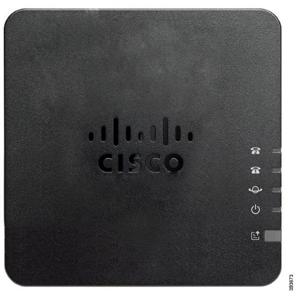
ATA 191 and ATA 192 Top Panel
The following figure shows the different LEDs and buttons found on the top of your ATA.
|
Item |
Description |
|---|---|
|
Power LED
|
Steady green: System booted up successfully and is ready for use. Slow flashing green: System is booting up. Fast flashing green three times, then repeats: System failed to boot up. Fast flashing green: The LED behaviour occurs in the following situations:
Off: Power is off. |
|
Network LED
|
Flashing green: Data transmission or reception is in progress through the WAN port. Off: No link. |
|
Phone 1 LED Phone 2 LED
|
Steady green: On hook. Slow flashing green: Off hook. Fast flashing green three times, then repeats: The analog device failed to register. Fast flashing green: A factory reset is performed successfully. Off: The port is not configured. |
|
Problem Report Tool (PRT) Button
|
Press this button to create a problem report using the Problem Report Tool. This button is not a power button. When you press this button, a problem report is generated and uploaded to a server for the system administrator. |
|
Problem Report Tool (PRT) LED
|
Flashing amber: The PRT is preparing the data for the problem report. Fast Flashing amber: The PRT is sending the problem report log to the HTTP server. Solid amber: The activation of the FIPS mode failed. Press the PRT button to turn off the PRT LED. Solid green for five seconds, then off: The PRT report was sent successfully. Fast flashing green: A factory reset is performed successfully. Flashing red: The PRT report failed. Press the PRT button once to cancel the flashing, then press again to trigger a new PRT. |


Problem Report Tool Button
The Problem Report Tool (PRT) button is on the ATA top panel. Press the PRT button, and a log file is prepared and uploaded to the server for troubleshooting your network.
You can instruct your analog phone users to press the PRT button on the ATA device to start the PRT log file process.
One of the following must be completed to upload the PRT log file from the ATA:
-
Set up the HTTP server to upload the PRT log file from the ATA.
-
Configure the customer support upload URL to best suit your needs, and apply it to the ATA.
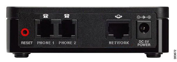
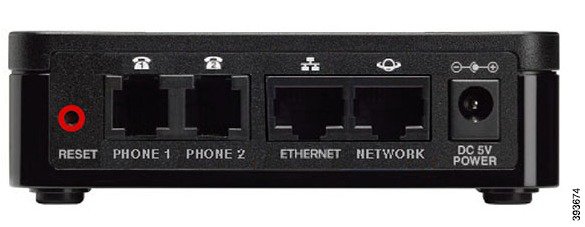
ATA 191 and ATA 192 Back Panel
The following figures shows the different ports and buttons found on the back of your ATA.
|
Item |
Description |
|---|---|
|
RESET |
To restart the ATA, use a paper clip or similar object to press this button briefly. To restore the factory default settings, press and hold for about 10 seconds. The LED behaviour for the factory reset:
|
|
PHONE 1 |
Use an RJ-11 phone cable to connect an analog phone or fax machine. |
|
PHONE 2 |
Use an RJ-11 phone cable to connect a second analog phone or fax machine. |
|
ETHERNET (ATA 192 only) |
Use an Ethernet cable to connect your ATA to a device on your network, such as a computer. |
|
NETWORK |
Use an Ethernet cable to connect to the network. |
|
DC 5V POWER |
Use the power adapter that was provided to connect to a power source. |
Deployment Workflow
To successfully deploy your Ciaso ATA, you perform the following tasks in order.
Enable WAN Port on Your Cisco ATA 192
The Cisco ATA 192 has a combined Wide Area Network (WAN) and Local Area Network (LAN) port, but WAN access is disabled by default. You enable WAN access before you install the ATA.
Before you begin
You need the default password and login for your ATA gateway, and a working internet connection with a browser.
| 1 |
Connect the network cable to your network and to the ETHERNET port on the ATA. |
| 2 |
Enter the IP address 192.168.15.1 in your web browser address bar. |
| 3 |
Log in to the default gateway. |
| 4 |
Navigate . |
| 5 |
Enable the Remote Management setting. |
Install Your New ATA 191 and 192
Before you begin
Before you begin the installation, make sure you have the following equipment:
-
Ethernet cable to connect to your network.
-
Analog phone or fax machine to connect to your ATA.
-
Phone cable to connect your phone.
-
Uninterruptible power supply (UPS) to provide backup power.
| 1 |
Connect the network cable to your network and to the NETWORK port on the ATA.
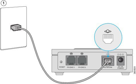 |
| 2 |
Connect the phone cable to the PHONE 1 port on the ATA and to your analog device (phone or fax machine).
 If connecting a fax machine, connect it directly to the ATA. Do not connect an extension to a fax machine, and do not use a splitter. |
| 3 |
(Optional) If you have a second analog device, connect the phone cable to the PHONE 2 port on the ATA and to your second analog device. |
| 4 |
Connect the ATA power cable to the DC 5V POWER port on the ATA, and plug the power cable into your power source.
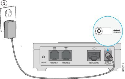 |
Reset Your Cisco ATA 191 and 192 to the Factory Settings
Reset your ATA to restore the device to the factory configuration settings.
Before you begin
Obtain a small paperclip.
| 1 |
Locate the Reset button on the back of your ATA. |
| 2 |
Use the paper clip to press and hold the reset button for 10 seconds. The ATA LEDs turn off and on. The device restarts and begins the factory reset process. The process is complete when the LEDs stop blinking. |
Change the Phone Adapter Configuration Utility Login
Change your login credentials to ensure your device remains secure.
Before you begin
Before you change your login credentials, make sure you have the following equipment:
-
An Internet browser with a working Internet connection
-
The login credentials for your ATA configuration utility
| 1 |
On your analog phone, press **** to access the IVR. |
| 2 |
Press 110# to hear the ATA IP address. |
| 3 |
Enter the ATA IP address in your Internet browser address bar. |
| 4 |
Login to the ATA configuration utility. |
| 5 |
Select . |
| 6 |
Navigate |
| 7 |
Enter the new password in the New Password field. |
| 8 |
Confirm your password by entering it in the Confirm New Password field. |
| 9 |
Click Submit . |
Firmware Upgrade
Use the page to upgrade the firmware on the ATA. It is not necessary to upgrade unless you are experiencing problems with the ATA or if the new firmware has a feature that you want to use.
Upgrading the firmware may take several minutes. Until the process is complete, DO NOT turn off the power, press the hardware reset button, or click the Back button in your current browser.
Before you begin
Before upgrading the firmware, download the firmware upgrade file for the ATA.
| 1 |
Click Browse and select the location of the upgrade file that you downloaded. |
| 2 |
Click the Upgrade button to upgrade the firmware. |
Provision your ATA 191 and 192 for Webex Calling
Your ATA may have older configuration files configured on it. To resolve this issue, you configure the Provisioning server to point to the server address and download the new files.
After you have completed this task, your ATA only works for Webex Calling and you are locked out of the ATA configuration utility.
Before you begin
Before you configure your Cisco ATA 191 or 192, make sure you have the following equipment:
-
An Internet browser with a working Internet connection
-
The login credentials for your ATA configuration utility
You must have completed the initial cable installation and have performed a factory reset before you attempt the ATA configuration.
You must also have upgraded your ATA to the latest firmware release before you provision the device.
| 1 |
On your analog phone, press **** to access the IVR. |
| 2 |
Press 110# to hear the ATA IP address. |
| 3 |
Enter the ATA IP address in your Internet browser address bar. |
| 4 |
Login to the ATA configuration utility. |
| 5 |
Navigate to . |
| 6 |
In the Profile Rule field, enter the Provisioning server address.
|
| 7 |
Select Submit. Your ATA restarts and begins to synchronize with the Provisioning server. |
Install Your New ATA 191 and 192
Before you begin
Before you begin the installation, make sure you have the following equipment:
-
Ethernet cable to connect to your network.
-
Analog phone or fax machine to connect to your ATA.
-
Phone cable to connect your phone.
-
Uninterruptible power supply (UPS) to provide backup power.
| 1 |
Connect the network cable to your network and to the NETWORK port on the ATA.
|
| 2 |
Connect the phone cable to the PHONE 1 port on the ATA and to your analog device (phone or fax machine).
If connecting a fax machine, connect it directly to the ATA. Do not connect an extension to a fax machine, and do not use a splitter. |
| 3 |
(Optional) If you have a second analog device, connect the phone cable to the PHONE 2 port on the ATA and to your second analog device. |
| 4 |
Connect the ATA power cable to the DC 5V POWER port on the ATA, and plug the power cable into your power source.
|
Automatically onboard or manually configure your ATA device
Your Cisco 191/192 ATA devices use EDOS to automatically onboard if they are provisioned with a MAC address in the Control Hub. The automatic onboarding completes after the first factory boot or after each factory reset.
In certain circumstances, you must manually configure the Cisco ATA 191/192 to connect to the Webex Calling platform.
Before you begin
-
You may need to factory reset the ATA to start the manual onboarding process.
-
Once the Cisco ATA 191/192 manual reconfiguration is complete, any prior configuration settings on the device are overwritten, including the administrator password, and the device is only usable on the Broadsoft Broadcloud PBX network.
-
Return the device to the factory default configuration before using it on any network other than Broadsoft Broadcloud PBX.
-
Ensure the devices are on the minimum firmware of 11-1-0MPP0414-004.
Factory Default Instructions
Press and hold the reset button on the back of the ATA for 10 seconds. After releasing the ATA's LED's turn off. If your device is a 191, you can skip steps 1-4.
When you enable Remote Management, you’re asked to change the admin password. To change the admin password, go to . Enter the old password ("admin") and then enter the new password.
| 1 |
From a factory default baseline on a Cisco 192 ATA device, plug an Ethernet cable into to the Ethernet slot of the device. |
| 2 |
Enter this IP address into your browser 192.168.15.1 to be prompted for login. |
| 3 |
Log in to the device using the default (case-sensitive) username ("admin") and password ("admin"), and then click Log In. |
| 4 |
Navigate to Administration tab. In the Remote Access section, click the radio button Enabled next to Remote Management. |
| 5 |
Plug in an Ethernet cable into the Network slot on the device. |
| 6 |
Plug in an analog phone into the device and press ****. The IVR announces you are on the phones configuration menu. |
| 7 |
Press 110#. The IVR menu begins to announce the phone’s IP address. |
| 8 |
Enter the IP address into your browser and log in with username (“admin”). |
| 9 |
Navigate to the Voice section then click Provisioning. |
| 10 |
In the Profile Rule field, enter the Provisioning server address.
|
| 11 |
Click Submit. The device requests the files from the provisioning server and reboots. Once the boot process completes, the device is provisioned for use in the BroadSoft BroadCloud PBX network. If the station assignment process was properly completed before the reboot, the device boots into a station-specific assigned/usable state. If not, the device boots into a default unassigned/unusable state, and remains in this state until you complete the station assignment process. |
Supported ATA 191 and 192 Call Features
Depending on your system configuration, your ATA supports some or all the following call features:
-
Transfer (attended or supervised)—In this type of transfer, you talk to the receiving party before you complete the transfer.
-
Transfer (unattended or unsupervised)—In this type of transfer, you complete the transfer and hang up before the receiving party answers.
-
Conference.
-
Hold and Resume.
-
Caller ID.
-
Call Waiting.
-
Call Pickup.
-
Speed Dial.
-
Music On Hold.
-
Shared Lines.
-
Voicemail—This feature has no visual indicator, but a message waiting tone when you go off-hook indicates that you have voice messages. Some analog phones with a large LCD screen may display a voicemail icon.
-
Call Forward.
-
Redial.


