- Home
- /
- Article

Thanks for your feedback.

 In this article
 Feedback?
The Cisco Desk Phone 9800 Key Expansion Module (KEM) enhances the phone by providing additional extension lines and programmable buttons. These buttons can be configured as line keys, speed-dial buttons, or other supported phone feature buttons.
Key Expansion Module overview

Each Cisco Desk Phone 9800 Key Expansion Module (KEM) The Cisco Desk Phone 9800 Key Expansion Module (KEM) supports 40 lines, with two pages of 20 buttons each.
You can use more than one expansion module per phone on the 9861 and 9871 models. But each module must be the same type. The following table lists the phones and the number of key expansion modules that each model supports.
|
Phone model |
Supported total number of KEMs and lines |
|---|---|
|
Cisco Desk Phone 9851 |
Supports 1 KEM and 46 lines (6 lines on phone) |
|
Cisco Desk Phone 9861 |
Supports up to 3 KEMs and 130 lines (10 lines on phone) |
|
Cisco Desk Phone 9871 |
Supports up to 3 KEMs and 124-128 lines, depending on configuration (4 or 8 lines on phone screen) |
-
When your 9861 and 9871 phones are powered over Ethernet (PoE), you can only connect one KEM to each phone. To connect two or three KEMs, use an adapter to power your phone from an electrical outlet.
-
The calling system that your phone is registered with restricts the maximum number of SIP lines available on the phone. The supported lines in the table above include both SIP lines and feature line keys (PLK).
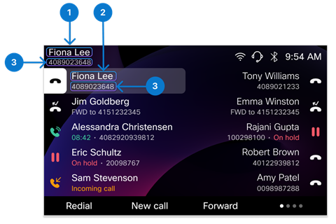
Key Expansion Module buttons and hardware
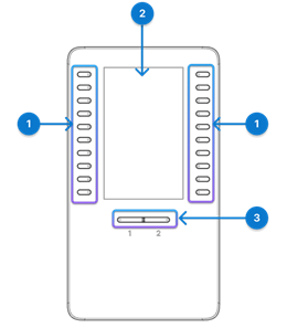
The following table describes the features of the key expansion module.
| Hardware | Description |
|---|---|
| 1. Line keys |
Each button corresponds to one line. The light of each button indicates the state of the corresponding line as follows: The light of button indicates the state of the corresponding line as follows:
The LEDs also reflect the status of the extended features assigned to the buttons. |
| 2. LCD screen |
LCD screen—Displays the phone number, speed-dial number (or name or other text label), phone service, or phone feature assigned to each button. Icons that indicate line status resemble (in both appearance and function) the icons on the phone to which the KEM is attached. |
| 3. Shift buttons |
Shift buttons—2 buttons. The button for page 1 is labeled as 1 and the button for page 2 is labeled as 2. The lights in each button indicate the state of the page as follows:
|
 Light off—Line is idle or not configured.
 Green steady—Line is in use.
 Red steady—Shared line or monitored line is in use
remotely.
Red steady—Shared line or monitored line is in use
remotely. Amber blinking—Line has an incoming call.
 Green steady LED—Page is in view.
 Light off—Page is not in view.
 Amber steady LED—Page is not in view with one or more alerting calls on the page.
 Install Key Expansion Module
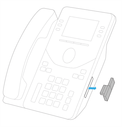
Connect the Key Expansion Module (KEM) to the phone. Depending on the calling system that your phone is registered with, you may need to contact your administrator to enable the KEM before you can use it.
| 1 |
Remove the accessory connector cover.
|
| 2 |
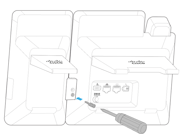
Firmly press the USB connector attached to the module to the phone. 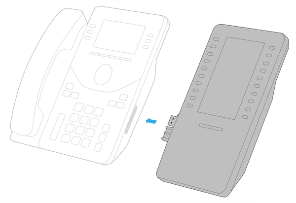
|
| 3 |
Fasten the screw into the phone.
After you firmly attach the module to the phone, the front screen of the phone and KEM appears as following.
An automatic upgrade will initiate if the firmware version on the KEM is lower than that on the phone. Wait until the update is complete.
|
Configure speed dials on KEM
The line keys on the Key Expansion Module (KEM) function similarly to the line keys on the phone itself. Depending on your phone settings, you can configure idle line keys with speed dials.
For more information about how to configure and use speed dials on line keys, see Use speed dials on your phone.
Change KEM screen settings
The wallpaper, color theme, and brightness settings on phone also apply to the KEM screen.
For information about how to adjust screen brightness and change the screen appearance, see Customize the phone screen settings.
Administration for KEM
If your Cisco Desk Phone 9800 Series is registered to Webex Calling, follow the information in this section to set up the line keys on the attached Key Expansion Modules.
Cisco Desk Phone 9871 natively supports up to 32 virtual line keys on the touchscreen. When a KEM is attached, you can specify whether to retain 4 lines or 8 lines on the phone, and move the additional lines to the KEM.
Before you begin
Connect your KEM to the the phone.
| 1 | From the customer view in Control Hub, go to Devices, and then select your phone. |
| 2 | Select All configurations. |
| 3 | In the Att Console section, choose 4 or 8 for Maximum Lines On Phone With KEM. By default, the field is set to 4. The additional extension lines and feature lines are moved to the attached KEMs. |
| 4 | Select Next. |
| 5 | Review your changes and select Apply. |
| 6 | Select Close to close the page. |
The KEM line keys can be configured as primary or shared lines, as well as feature keys.
Use the custom layout to individually customize the KEM line keys.
To help you customize your phone layout, the portal alerts you if the quantities on the device’s shared line list or your monitoring list don't match your active layout. The alerts are called advisories and appear just above the layout area. Advisories are informational messages only and don't prevent you from saving the layout that you create. You can clear advisories by either adding more PLK positions of the required type to your layout or by reducing the entries in the device’s shared line list or the user’s monitoring list.
Before you begin
Connect your KEM to the phone.
| 1 | From the customer view in Control Hub, go to Devices, and then select your phone. |
| 2 | Under Device Management, select Configure Layout and then select Custom Layout. |
| 3 | Do one of the following action based on your phone model:
|
| 4 | Choose one of the following options for each line key you'd like to modify:
|
| 5 | Select Save. |
 At the bottom of the page, select
  Go to Step 4.
In Control Hub, you can choose a predefined number or name format to display as the line label for configured lines.
The configurations are also applicable for Key Expansion Module (KEM).
The following example shows the positions of the configurable line key labels:
| Index | Label Name | Description |
|---|---|---|
| 1 | Display Name | For the primary line only. It shows on the top left of the phone screen. |
| 2 | Line Key Label | For any other lines (except for the primary line) on the phone with multiple lines. It's the first line when the secondary label is enabled. It also supports the multiple appearances for a same line (suffixed with a -1, -2, and so on). |
| 3 | Line Key Secondary Label | For all lines. It shows as the second line label for the primary line and line keys. |
| 1 | From the customer view in Control Hub, go to Devices, and then select your phone. |
| 2 | Ensure that the value of Line Label is set to default or empty. |
| 3 | On the device details page, select All Configurations in the Configurations section. |
| 4 | In the Phone section, configure the parameters Display Name, Line Key Label, and Line Key Secondary Label. For more information about the parameters, see Parameters for configurable line key labels on Control Hub. |
| 5 | Click Next, review your changes, and then click Apply. |
Parameters for configurable line key labels on Control Hub
| Parameter | Default and options | Description |
|---|---|---|
| Display Name | Default:
Options:
|
For the option User Phone Number / Location Number / User Extension, the display priority is: User Phone Number > Location Number > User Extension. If User Phone Number is empty, then the phone will display Location Number. Meanwhile, if the Location Number is also empty, then the phone will display User Extension. If the actual values of "Display Name" and "Line Key Label" are identical, the secondary line label on the primary line doesn't display. |
| Line Key Label | Default: User Name (First Name Last Name) Options:
|
For the option User Extension / First Name, the display priority is: User Extension > First Name If User Extension is empty, then the phone will display First Name. If a line is configured with multiple appearances, the suffix (-1, -2, and so on) is appended to the Line Key Label. |
| Line Key Secondary Label | Default: User Phone Number / Location Number / User Extension Options:
| If set to None, the phone doesn't display the secondary label on the line key. In this case, only one line label displays on the phone (including the primary line on the upper left corner of the phone screen). If the actual values of "Line Key Label" and "Line Key Secondary Label" are identical, the secondary label on the line key will only display the string "Line". |
 For
9841/9851: User Phone Number / Location Number / User Extension
For
9841/9851: User Phone Number / Location Number / User Extension For
9861/9871/8875: User Name (First Name Last Name)
For
9861/9871/8875: User Name (First Name Last Name)If your Cisco Desk Phone 9800 Series is registered to Cisco Unified Communications Manager (Unified CM), follow the information in this section to set up the attached Key Expansion Modules.
Enable the KEMs that are attached to the phone on Cisco Unified CM Administration before your users can use them.
Before you begin
- Connect your KEM to your phone.
- Make sure the side USB port is enabled.
| 1 |
On Cisco Unified CM Administration, choose . |
| 2 |
Click Find and use the filters to search for your phone. |
| 3 |
Click the device name of your phone to open the Phone Configuration page. |
| 4 |
In the Expansion Module Information section, choose your KEM in the module drop-down list. By default, the fields are set to None. The module appears in the list only when it's connected to the phone.
|
| 5 |
Click Save. |
| 6 |
Click Apply Config. |
Cisco Desk Phone 9871 natively supports up to 32 virtual line keys on the touchscreen. With three KEMs connected, it can support up to 124 or 128 lines depending on the Unified CM configurations. When a KEM is attached, you can specify whether to retain 4 lines or 8 lines on the phone, and move the additional lines to the KEM.
| 1 |
On Cisco Unified CM Administration, choose . |
| 2 |
Click Find and use the filters to search for your phone. |
| 3 |
Click the device name of your phone to open the Phone Configuration page. |
| 4 |
In the Maximum lines on phone with KEM field, choose 4 or 8. By default, the field is set to 4. The additional extension lines and feature lines are moved to the attached KEMs.
|
| 5 |
Click Save. |
| 6 |
Click Apply Config. |
The Key Expansion Module (KEM) line keys function similarly to the line keys on the phone itself. You can configure the KEM line keys following the same steps. When the number of lines exceeds the phone's maximum capacity, they extend to the attached KEMs.
You can use the phone button template to arrange the sequence of the extension lines and feature lines.
Cisco Unified Communications Manager (Unified CM) supports up to 126 SIP lines on a phone. If you have three KEMs attached to Cisco Desk Phone 9861 and 9871, keep the following limitation in mind:
-
- 9861: Don't assign extension numbers to the last four line keys on the third KEM. Instead, you can add features on them.
- 9871: Don't assign extension numbers to the last two line keys on the third KEM. Instead, you can add features on them.
| 1 |
On Cisco Unified CM Administration, choose . |
| 2 |
Use the filters to find your phone to configure. |
| 3 |
Click the device name of your phone to open the Phone Configuration page. |
| 4 |
Click Line [n] - Add a new DN in the Association pane on the left. |
| 5 |
In the Directory Number Configuration window, enter a dialable phone number in the Directory Number field. |
| 6 |
(Optional) Select a partition in the Rout Partition field. |
| 7 |
(Optional) Select a calling search space in the Calling Search Space field in the Directory Number Settings area. |
| 8 |
Click Save. |
You can add the features listed in the following table to line keys on Cisco Desk Phone 9800 Series and their attached KEMs.
| Feature name | Description |
|---|---|
| BLF with Call Park | Use the Call Park BLF feature in the phone button template to control this shortcut. |
| BLF with Call Pickup | Use the Speed Dial BLF feature in the phone button template and enable the checkbox Call Pickup in the Busy Lamp Field Speed Dial Configuration window to control this shortcut. |
| BLF with Speed Dial | Use the Speed Dial BLF feature in the phone button template to control this shortcut. |
| Call Park | Use the Call Park feature in the phone button template to control this shortcut. |
| Call Pickup | Use the Call Pickup feature in the phone button template to control this shortcut. |
| DND | Use the Do Not Disturb feature in the phone button template to control this shortcut. |
| Group Pickup | Use the Group Call Pickup feature in the phone button template to control this shortcut. |
| Hunt Group | Use the Hunt Group Logout feature in the phone button template to control this shortcut. |
| Intercom | Use the Intercom feature in the phone button template to control this shortcut. |
| Malicious Call Identification | Use the Malicious Call Identification feature in the phone button template to control this shortcut. |
| Meet Me | Use the Meet Me Conference feature in the phone button template to control this shortcut. |
| Other Pickup | Use the Other Pickup feature in the phone button template to control this shortcut. |
| Privacy | Use the Privacy feature in the phone button template to control this shortcut. |
| Queue Status | Use the Queue Status feature in the phone button template to control this shortcut. |
| Redial | Use the Redial feature in the phone button template to control this shortcut. |
| Speed Dial | Use the Speed Dial feature in the phone button template to control this shortcut. |
| XSI Service | Use the Service URL feature in the phone button template to control this shortcut. |
We recommend using a phone button template to configure KEM line keys. These templates work for both phones and KEMs, allowing additional lines beyond the phone's maximum to flow to the KEM line keys.
Configure feature line keys with a phone button template
You can use the Phone Button Template on Cisco Unified Communications Manager Administration to configure the feature line keys for different features. Each feature line key takes up a line position. You can change the order of the feature.
| 1 |
On Cisco Unified Communications Manager Administration, choose . |
| 2 |
Click Find to display list of supported phone templates. |
| 3 |
Perform the following steps if you want to create a new phone button template; otherwise, proceed to the next step. |
| 4 |
Perform the following steps if you want to add phone buttons to an existing template. |
| 5 |
From the Line drop-down list, choose feature that you want to add to the template. |
| 6 |
Click Save. |
| 7 |
Perform one of the following tasks:
|
Apply a button template to a phone
| 1 |
On Cisco Unified Communications Manager Administration, choose . |
| 2 |
Click Find to display the list of configured phones. |
| 3 |
Choose the phone to which you want to add the phone button template. |
| 4 |
In the Phone Button Template drop-down list, choose the phone button template that contains the new feature button. |
| 5 |
Click Save. A message prompts for clicking Reset to update the phone
settings.
|
| 6 |
Click Reset. |
The wallpaper and color theme on the phone screen also applies to the attached Key Expansion Modules (KEM). The logo displays only on the phone screen and does not appear on the KEM screen.
To deploy your custom wallpaper and logo to your phones, follow this workflow:
- Prepare your wallpaper and logo images
- Upload the images files to the TFTP server
- Create a general management file List.xml
- Upload the List.xml to the TFTP server
- Restart the TFTP server
- Configure the wallpaper settings on Cisco Unified Communications Manager Administration
See the following for procedures:
To get the best experience, keep the following tips in mind when choosing or designing your images:
- Avoid using clustered images that can make it hard for you to identify phone lines on the home screen. Simplicity is key when selecting wallpapers.
- Ensure that your chosen wallpapers match your phone's color scheme. Opt for wallpapers that complement either the dark or light color palettes. Dark images are best suited for dark mode, while light images work well for light mode.
- Avoid using high contrast images as wallpapers. The extreme contrast can make it challenging to see the logo and other screen elements against the background.
- Avoid using dynamic images as wallpapers.
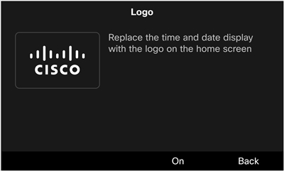
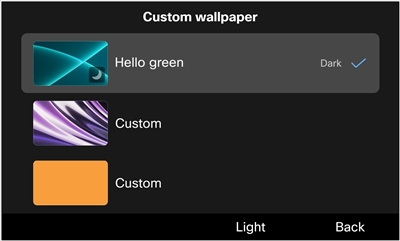
- The logo displays on the phone screen only, and it doesn't display on the KEM screen. When multiple lines are configured on Cisco Desk Phone 9841, 9851, and 9861, the logo and the logo setting in the Settings menu are unavailable.
- To use custom wallpaper on phones with Key Expansion Modules (KEM) attached, prepare both phone wallpaper and KEM wallpaper.
| Image | Supported format (Unified CM) | Recommended dimensions (pixels) | Description |
|---|---|---|---|
| Logo | PNG |
Cisco Desk Phone 9851: 190x125 Cisco Desk Phone 9861: 380x250 Cisco Desk Phone 9871: 494x325 / 418x275 Cisco Video Phone 8875: 380x250 | Images that don't match the recommended dimensions will be scaled
proportionally. You don't need to create a separate thumbnail image for the logo. The system automatically scales the logo image to fit the dimensions of the thumbnail. |
| Wallpaper |
Cisco Desk Phone 9851: 480x240 Cisco Desk Phone 9861: 800x480 Cisco Desk Phone 9871: 1280x720 Cisco Desk Phone 9800 Key Expansion Module: 480x800 Cisco Video Phone 8875: 1024x600 | Images that don't match the recommended dimensions may be scaled to fit the phone screen, which may cause the image to become distorted. | |
| Wallpaper thumbnail |
Cisco Desk Phone 9851: 100x56 Cisco Desk Phone 9861: 150x90 Cisco Desk Phone 9871: 228x128 Cisco Video Phone 8875: 180x100 | Images that don't match the recommended dimensions may cause certain issues on the phone. |
| Phone Model | Maximum size per image | Maximum number of images | Limit size |
|---|---|---|---|
| Cisco Desk Phone 9851 | 250KB | 10 | 250KB x 10 |
| Cisco Desk Phone 9861 | 1MB | 20 | 1MB x 20 |
| Cisco Desk Phone 9871 | 1MB | 20 | 1MB x 20 |
| Cisco Video Phone 8875 | 1MB | 20 | 1MB x 20 |
| 1 |
Choose your desired logo and wallpaper images. |
| 2 |
Format the images to meet the required specifications as described in the table above. |
| 3 |
Rename the wallpaper image files in this format:
|
The system uses the List.xml file to manage the wallpaper and logo files. In the file, you can specify the wallpapers and the logo available in the phone custom wallpaper settings. The List.xml file must be uploaded to the repository where you store the image files for a particular phone model.
Here is an example of the definitions in a general management file:
<CiscoIPPhoneImageList version="1.0">
<!-- Please Add Images to the end of the list-->

<ImageItem Name="Blue"
Image="TFTP:Desktops/DP-9871/wallpaper-blue.png"
Thumbnail="TFTP:Desktops/DP-9871/thumbnail-blue.png"
Theme = "dark"/>

<ImageItem Name="Purple"
Image="TFTP:Desktops/DP-9871/wallpaper-purple.png"
Thumbnail="TFTP:Desktops/DP-9871/thumbnail-purple.png"
Theme = "dark"/>

<ImageItem Name="logo"
Image="TFTP:Desktops/DP-9871/logo.png"/>

</CiscoIPPhoneImageList>| Element | Description | Example |
|---|---|---|
| Root element |
Make sure you include the root element If you upload a new XML file or update the existing one, make sure to do the following actions:
|
|
| Wallpaper item element |
You can add multiple
|
|
| Logo item element | Your phone supports only one logo to be added. The logo item element also uses the ImageItem element but has the following two parameters.
|
|
The following figure shows the Logo and Custom wallpaper setting screens:
Before you begin
Obtain the file path on the TFTP server that you've uploaded the wallpaper and logo images to.
| 1 |
Create a new file with your text editor or XML editor. |
| 2 |
Add the elements with the information of your image files included. The file path and file names are case-sensitive. Make sure you enter them correctly. |
| 3 |
Save the file as List.xml. |
Upload the List.xml file and all your wallpaper and logo image files to the TFTP server. After you apply the custom wallpaper settings on Cisco Unified Communications Manager, your phones download the images from the server.
Desktops/model-nameUpload your phone wallpaper images, logo image, and the List.xml file to the model-specific folder. Make sure the folder name matches your phone model. You can find the model name on the back of your phone. For example, DP-9851, DP-9861, DP-9861NR, DP-9871, DP-9871NR.
Desktops/480x800x24Upload your KEM wallpaper images to this folder.
| 1 |
On Cisco Unified Communications Manager Administration, select Cisco Unified OS Administration in the Navigation field and click Go. 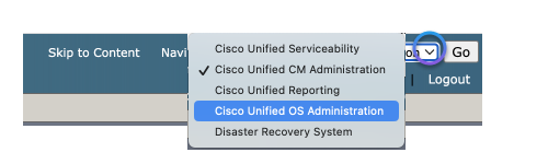
|
| 2 |
Select . |
| 3 |
Click Choose File and select the file to upload in your local drive. |
| 4 |
Specify the upload directory for the wallpaper image. |
| 5 |
Click Upload File. |
| 6 |
Repeat Step 3 through Step 5 to upload more files. |
What to do next
Restart the TFTP server.
To apply the changes that you've made, restart the TFTP server.
| 1 |
On Cisco Unified Communications Manager Administration, select Cisco Unified Serviceability in the Navigation field and click Go. |
| 2 |
Navigate to . |
| 3 |
Select your server and click Go. |
| 4 |
Select Cisco TFTP in the CM Services section. |
| 5 |
Click Restart. |
As an administrator, you can designate the wallpaper image that will be applied to the deployed phones. If you grant users access to the appearance settings on their phones, they can choose whether to display the logo and select their preferred wallpaper from the provided options. However, if you do not grant them access, the appearance settings will be hidden on the phones.
Before you begin
Before you start configuring the wallpaper settings on Cisco Unified Communications Manager Administration, finish the following actions first:
- Prepare your wallpaper and logo images
- Create a general management file (List.xml)
- Upload the List.xml file and the image files to the TFTP server
| 1 |
Log in to Cisco Unified Communications Manager Administration. |
| 2 |
Navigate to . |
| 3 |
Locate and click the profile that your phones are using. |
| 4 |
In the Common Phone Profile Information section, check the check box of Enable End User Access to Phone Background Image Setting if you want to allow users to change the phone screen background image. Otherwise, leave the check box unchecked. |
| 5 |
Go to the Product Specific Configuration Layout section and enter the filename of the wallpaper image file in the Background Image field. It's important to enter the exact filename that you specified in the List.xml file. If you enter a wrong filename, the system will fail to load the wallpaper. |
| 6 |
Click Save and then Apply Config. |
| 7 |
Restart the phones. |
In addition to uploading a prepared XML file to a TFTP server, you can also directly send an XML request to the phone to customize the wallpaper of the phone and KEM screens.
| 1 |
Log in to Cisco Unified Communications Manager Administration. | |||||||||||||||||||||
| 2 |
Do one of the following actions as needed:
| |||||||||||||||||||||
| 3 |
Set Phone Personalization to Enabled. | |||||||||||||||||||||
| 4 |
Associate the phone to the user. | |||||||||||||||||||||
| 5 |
Prepare an HTML file that contains the XML information specified for customized wallpaper. Here's an example of the HTML file:
| |||||||||||||||||||||
| 6 |
Save and file to your local disk, and open it with a web browser, and then click the button. The wallpaper will be pushed to the phone. When the configuration is complete, the users can view and set the wallpaper as usual on the phone screen.
| |||||||||||||||||||||
| 7 |
(Optional) To remove the custom wallpaper from the phone, do the following: |
If your Cisco Desk Phone 9800 Series is registered to Cisco BroadWorks, follow the information in this section to set up the attached Key Expansion Modules.
The 9851 phone supports one Key Expansion Module (KEM); the 9861 and 9871 phones support up to three KEMs. You can specify the number of KEMs that can be used on the 9861 and 9871 phones. You can also disable the attached KEMs.
Before you begin
- Access the phone web interface.
- Make sure the side USB port on the phone is enabled.
| 1 |
Select . |
| 2 |
In the General section, select an option from the drop-down list of Number of Units. Setting the value to 0 disables all the connected KEMs. Setting the value to 2 for a phone with three KEMs disables the third KEM. Default: 1 (for 9851); 3 (for 9861 and 9871) Options for 9851: 0, 1 Options for 9861 and 9871: 0, 1, 2, 3 You can also configure this parameter in the phone configuration file (cfg.xml). Enter a string in this format:
|
| 3 |
Click Submit All Changes. |
Cisco Desk Phone 9871 natively supports up to 32 virtual line keys on the touchscreen. With three KEMs connected, it can support up to 124 or 128 lines depending on the Unified CM configurations. When a KEM is attached, you can specify whether to retain 4 lines or 8 lines on the phone, and move the additional lines to the KEM.
Before you begin
Access the phone administration web page.
| 1 |
Select . |
| 2 |
In the Number of Phone Lines field, choose 4 or 8. By default, the field is set to 4. The additional extension lines and feature lines are moved to the attached KEMs. You can also configure this parameter in the phone configuration file (cfg.xml). Enter a string in this format:
|
| 3 |
Click Submit All Changes. |
You can assign an extension number to a key expansion module line key so that the line key can be used as a SIP line.
Before you begin
Access the phone administration web page.
| 1 |
Access the KEM settings in the way that's applicable to your phone model.
|
| 2 |
Go to the section of the KEM line key that you want to configure. |
| 3 |
Select a number from 1 to 16 in the Extension drop-down list. You can also configure this parameter in the phone configuration file (cfg.xml). Enter a string in this format:
where, replace the n and m with the corresponding unit number and line key number.
where, n is the line key number. |
| 4 |
Click Submit All Changes. |
You can add a feature to a line key of the attached KEM. Then, the user can press the line key to access the feature. For the supported features, see Programmable features on line keys.
Before you begin
Access the phone administration web page.
| 1 |
Access the KEM settings in the way that's applicable to your phone model.
|
| 2 |
Go to the section of the KEM line key that you want to configure. |
| 3 |
Enter a string in the Extended Function field in this format: For the supported features on line keys and the valid string syntax, see Programmable features on line keys. You can also configure this parameter in the phone configuration file (cfg.xml). Enter a string in this format:
where, replace the n and m with the corresponding unit number and line key number.
where, replace n with the KEM line key number. |
| 4 |
Click Submit All Changes. |
You can enable the user to configure features on the line keys of the key expansion module. The user can access the list of available features by pressing the line key and configure it with their desired feature.
Before you begin
Access the phone administration web page.
| 1 |
Select . | ||||||||||||||||||||||||
| 2 |
In the General section, configure the Customizable PLK Options parameter with the codes of your desired features. You can configure multiple features for line keys and separate each feature code with a semicolon. The user can add a feature to an empty line key, as well as edit or remove the existing feature.
You can also configure this parameter in the phone configuration file (cfg.xml). Enter a string in this format:
| ||||||||||||||||||||||||
| 3 |
Click Submit All Changes. |
You can shut down a line key on a KEM by setting it to Inert mode through the phone's web page. When a KEM line key is in Inert mode, it is completely disabled. For example, the LED on the line key is turned off, no icons or text are displayed next to the line key, and the line button is unresponsive. In short, it is completely unavailable.
Before you begin
Access the phone administration web interface.
| 1 |
Access the KEM settings in the way that's applicable to your phone model.
|
| 2 |
Go to the section of the KEM line key that you want to shut down. |
| 3 |
Enter
You can also configure this parameter in the phone configuration file (cfg.xml). Enter a string in this format:
where, replace the n and m with the corresponding unit number and line key number.
where, replace n with the KEM line key number. |
| 4 |
Click Submit All Changes. |


