- ホーム
- /
- 投稿記事


Webex Calling のサイトサバイバビリティ
 この記事の内容
 フィードバックがある場合
サイトの存続可能性により、Webex への接続が失われた場合でもビジネスへのアクセスが確保されます。ローカル ネットワーク ゲートウェイを使用して、ネットワーク障害時にオンサイト エンドポイントにフォールバック通話サービスを提供します。
展開に関する考慮事項
デフォルトでは、Webex Calling エンドポイントはアクティブ モードで動作し、SIP 登録と通話制御のために Webex クラウドに接続します。Webex へのネットワーク接続が失われた場合、エンドポイントは自動的に Survivability モードに切り替わり、ローカル Survivability Gateway に登録されます。このモードでは、ゲートウェイは基本的なバックアップ通話サービスを提供します。Webex へのネットワーク接続が復元されると、通話制御と登録は Webex クラウドに戻ります。
Survivability モードでは次の呼び出しがサポートされます。
-
サポートされている Webex Calling エンドポイント間の内部通話 (サイト内)
-
ローカル PSTN 回線または SIP トランクを使用した外部番号および E911 プロバイダーへの外部通話 (着信および発信)
この機能を使用するには、ローカル ネットワーク内の Cisco IOS XE ルータを Survivability Gateway として設定する必要があります。Survivability Gateway は、その場所にあるエンドポイントの通話情報を Webex クラウドから毎日同期します。エンドポイントが存続可能モードに切り替わると、ゲートウェイはこの情報を使用して SIP 登録を引き継ぎ、基本的な通話サービスを提供できます。
単一の場所のセットアップ
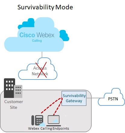
次の画像は、Webex への接続が切断され、Webex サイトのエンドポイントが Survivability モードで動作しているネットワーク障害のシナリオを示しています。この画像では、Survivability Gateway が Webex への接続を必要とせずに、2 つのオンサイト エンドポイント間の内部通話をルーティングしています。この場合、Survivability Gateway はローカル PSTN 接続で構成されます。その結果、生存性モードのオンサイト エンドポイントは、外部番号および E911 プロバイダーへの着信および発信通話に PSTN を使用できます。

複数の場所のセットアップ
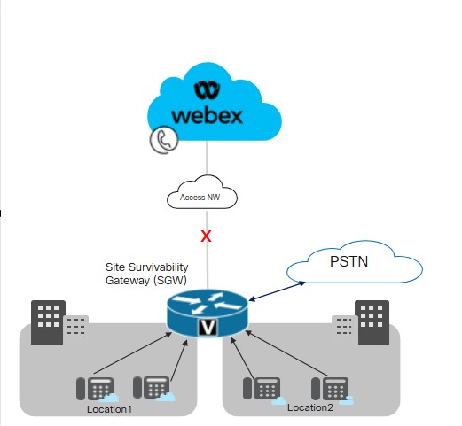
次の画像は、Webex への接続が切断され、異なる場所にあるエンドポイントが Survivability モードで動作しているネットワーク障害のシナリオを示しています。LAN ネットワーク内には、単一の Survivability ゲートウェイにマップされる小さな場所が複数あります。この展開により、通話ルーティングの場所固有の構成を維持しながら、ゲートウェイ リソースの使用率が最適化されます。

Cisco では、LAN 内の複数の場所にある Survivability Gateway とエンドポイント間の接続の遅延しきい値を 50 ミリ秒に維持することを推奨しています。
サイトの存続可能性のための重要な条件
Survivability Gateway には次の条件が適用されます。
-
Webex クラウドには、デバイス構成ファイルに Survivability Gateway の IP アドレス、ホスト名、およびポートが含まれています。その結果、Webex への接続が切断された場合、エンドポイントは登録のために Survivability Gateway にアクセスできるようになります。
-
Webex クラウドと Survivability Gateway 間の毎日の通話データ同期には、登録ユーザーの認証情報が含まれます。その結果、エンドポイントは、生存性モードで動作している間でも、安全な登録を維持できます。同期にはそれらのユーザーのルーティング情報も含まれます。
-
Survivability Gateway は、Webex が提供するルーティング情報を使用して、内部通話を自動的にルーティングできます。外部通話を可能にするために、Survivability Gateway に PSTN トランク構成を追加します。
-
Site Survivability を展開する各サイトには、ローカル ネットワーク内に Survivability Gateway が必要です。
-
Webex ネットワーク接続が少なくとも 30 秒間再開されると、登録と通話制御は両方とも Webex クラウドに戻ります。
統合 SRST によるコロケーション
Survivability Gateway は、同じゲートウェイ上での Webex Survivability 構成と Unified SRST 構成の共存をサポートします。ゲートウェイは、Webex Calling エンドポイントと、Unified Communications Manager に登録するエンドポイントの両方の存続可能性をサポートできます。コロケーションを構成するには:
-
Unified Communications Manager に登録するエンドポイントに対して Unified SRST サポートを設定します。設定については、 Cisco Unified SRST 管理ガイドを参照してください。
-
同じゲートウェイで、この記事の サイト存続可能性構成タスク フロー に従って、Webex Calling エンドポイントのサイト存続可能性を使用してゲートウェイを構成します。
コロケーションにおけるコールルーティングの考慮事項
コロケーション シナリオのコール ルーティングを構成するときは、次の点を考慮してください。
-
Survivability Gateway は、通話の両方のエンドポイントが Survivability Gateway に登録されている場合、内部通話を自動的にルーティングします。内部通話は、登録されたクライアント (SRST または Webex Calling) 間で自動的にルーティングされます。
-
一方の通話制御システムへの接続が切断され、もう一方の通話制御システムへの接続が維持される状況が発生する可能性があります。その結果、エンドポイントの 1 セットは Survivability Gateway に登録され、同じサイトにあるエンドポイントの別のセットはプライマリ コール制御に登録されます。この場合、2 セットのエンドポイント間の通話を SIP トランクまたは PSTN 回線にルーティングする必要がある場合があります。
-
外部通話および E911 通話は、SIP トランクまたは PSTN 回線にルーティングできます。
サポートされている機能とコンポーネント
次の表に、サポートされている機能に関する情報を示します。
| 機能 | MPPデバイスとWebexアプリ | VG4xx アタ |
|---|---|---|
|
サイト内内線通話 |
Survivability Gateway で特定のルーティング構成を必要とせず、自動的にサポートされます。 |
Survivability Gateway で特定のルーティング構成を必要とせず、自動的にサポートされます。 代替番号はサポートされていません。 |
|
サイト間および PSTN 通話 (着信および発信) |
電話回線または SIP トランクに基づく PSTN 通話。 |
電話回線または SIP トランクに基づく PSTN 通話。 |
|
E911通話処理 |
E911 通話には PSTN 回線または SIP トランクが必要です。 発信コールでは、定義された緊急対応場所 (ERL) に対して特定の登録済み緊急場所識別番号 (ELIN) が使用されます。緊急オペレータが切断された通話を返すと、Survivability Gateway は緊急番号に最後に電話をかけたデバイスに通話を転送します。 |
E911 通話には PSTN 回線または SIP トランクが必要です。 発信コールでは、定義された緊急対応場所 (ERL) に対して特定の登録済み緊急場所識別番号 (ELIN) が使用されます。緊急オペレータが切断された通話を返すと、Survivability Gateway は緊急番号に最後に電話をかけたデバイスに通話を転送します。 |
|
通話の保留と再起動 |
サポートあり 保留音 (MOH) を使用している場合は、MOH ファイルを使用して Survivability Gateway を手動でプロビジョニングします。 |
VG4xx ATA アナログ回線では通話を保留または再開できません。 この機能は、VG4xx ATA で着信コールが受信された場合にのみサポートされます。 |
|
在席転送 |
サポートあり |
この機能は、VG4xx ATA で着信コールが受信された場合にのみサポートされます。 |
|
ブラインドコール転送 |
サポートあり |
この機能は、VG4xx ATA で着信コールが受信された場合にのみサポートされます。 |
|
着信発信者 ID (名前) |
対応あり |
対応あり |
|
着信発信者ID(名前 & 番号) |
対応あり |
対応あり |
|
ポイントツーポイントビデオ通話 |
対応あり |
対応なし |
|
三者通話 |
対応なし |
対応なし |
|
共有回線 |
対応あり |
対応あり |
|
仮想回線 |
対応あり |
対応なし |
この機能を構成すると、サポートされている次のエンドポイントでサイト存続可能性が利用できるようになります。
| タイプ | モデル | 最小バージョン |
|---|---|---|
| マルチプラットフォーム(MPP)ファームウェア搭載のCisco IP Phone |
6821、6841、6851、6861、6861 Wi-Fi、6871 7811, 7821, 7841, 7861 8811, 8841, 8851, 8861 8845(音声のみ)、8865(音声のみ)、8875(ビデオ) 9800 マルチプラットフォーム (MPP) ファームウェアでサポートされている Cisco IP 電話の詳細については、以下を参照してください。 |
12.0(1) 8875 電話の場合 - 電話 OS 3.2 以降のバージョン 9800シリーズの場合 - PhoneOS 3.2(1) |
|
Cisco IP Conference Phone |
7832, 8832 |
12.0(1) |
|
Cisco Webex アプリ |
Windows、Mac |
43.2 |
|
アナログエンドポイント |
VG400 ATA、VG410 ATA、およびVG420 ATA Cisco ATA 191 および 192 |
17.16.1a ATA 191および192の11.3(1) |
Survivability Gateway ではサードパーティ デバイスはサポートされません。
次の表は、Cisco IOS XE ルータを Survivability Gateway として設定するのに役立ちます。この表には、各プラットフォームがサポートするエンドポイントの最大数と最小 IOS XE バージョンが示されています。
Webex Calling Survivability Gateway 機能は、Cisco IOS XE Dublin 17.12.3 バージョン以降のリリースで利用できます。
| モデル | エンドポイント登録の最大数 | 最小バージョン |
|---|---|---|
|
統合サービスルータ 4321 | 50 |
Cisco IOS XE Dublin 17.12.3 以降のリリース |
|
統合サービスルータ 4331 | 100 | |
|
統合サービスルータ 4351 | 700 | |
|
統合サービスルータ 4431 | 1200 | |
|
統合サービスルータ 4451-X | 2000 | |
|
統合サービスルータ 4461 | 2000 | |
|
Catalyst Edge 8200L-1N-4T | 1500 | |
|
Catalyst Edge 8200-1N-4T | 2500 | |
|
Catalyst Edge 8300-1N1S-6T | 2500 | |
|
Catalyst Edge 8300-2N2S-6T | 2500 | |
|
Catalyst Edge 8300-1N1S-4T2X | 2500 | |
|
Catalyst Edge 8300-2N2S-4T2X | 2500 | |
|
Catalyst Edge 8000V ソフトウェア小規模構成 | 500 | |
|
Catalyst Edge 8000V ソフトウェア中規模構成 | 1000 | |
|
Catalyst Edge 8000V ソフトウェア大規模構成 | 2000 |
Survivability Gateway のポート参照情報
|
接続目的 |
ソース アドレス |
ソース ポート |
プロトコル |
接続先アドレス |
宛先ポート |
|---|---|---|---|---|---|
|
生存性ゲートウェイへのコールシグナリング(SIP TLS) |
デバイス |
5060-5080 |
TLS |
サバイバビリティ ゲートウェイ |
8933 |
|
生存性ゲートウェイ (SRTP) へのメディアの呼び出し |
デバイス |
19560-19660 |
UDP |
サバイバビリティ ゲートウェイ |
8000-14198 (UDP 経由の SRTP) |
|
PSTNゲートウェイへの通話シグナリング(SIP) |
サバイバビリティ ゲートウェイ |
一時的 |
TCPまたはUDP |
ITSP PSTNゲートウェイ |
5060 |
|
PSTN ゲートウェイへのコール メディア (SRTP) |
サバイバビリティ ゲートウェイ |
8000-48198 |
UDP |
ITSP PSTNゲートウェイ |
一時的 |
|
時刻同期(NTP) |
サバイバビリティ ゲートウェイ |
一時的 |
UDP |
NTPサーバー |
123 |
|
名前解決(DNS) |
サバイバビリティ ゲートウェイ |
一時的 |
UDP |
DNSサーバー |
53 |
|
クラウド管理 |
コネクタ |
一時的 |
HTTPS |
Webex サービス |
443, 8433 |
クラウド モードの操作ガイダンスについては、 Webex Calling のポート参照情報 ヘルプ記事を参照してください。
Cisco IOS XE ルータのポート設定値をカスタマイズできます。この表では、ガイドラインとしてデフォルト値を使用しています。
機能構成
サイトの存続可能性の構成タスクフロー
既存の Webex Calling の場所にサイトの存続可能性を追加するには、次のタスクを完了します。Webex クラウドへの接続が切断された場合、ローカル ネットワーク内の Survivability Gateway がその場所のエンドポイントに対してバックアップの通話制御を提供できます。
開始する前に
Survivability Gateway として機能する新しいゲートウェイをプロビジョニングする必要がある場合は、Webex の記事「 Cisco IOS マネージド ゲートウェイを Webex Cloud に登録する 」を参照して、ゲートウェイを Control Hub に追加してください。
| ステップ | コマンドまたはアクション | 目的 |
|---|---|---|
|
1 | ゲートウェイに生存性サービスを割り当てる |
Control Hub で、 Survivability Gateway サービスをゲートウェイに割り当てます。 |
|
2 | 構成テンプレートをダウンロード |
Control Hub から構成テンプレートをダウンロードします。ゲートウェイのコマンド ラインを構成するときにテンプレートが必要になります。 |
|
3 |
Survivability Gateway のライセンスを構成します。 | |
|
4 |
Survivability Gateway の証明書を構成します。 | |
|
5 |
以前にダウンロードした構成テンプレートをガイドとして使用して、ゲートウェイ コマンド ラインを構成します。テンプレートにある必須構成をすべて完了します。 |
ゲートウェイに生存性サービスを割り当てる
開始する前に
| 1 |
サービスの下の [ 通話 に移動し、 管理ゲートウェイ タブをクリックします。 管理ゲートウェイ ビューには、Control Hub を通じて管理するゲートウェイのリストが表示されます。
|
| 2 |
Survivability Gateway として割り当てるゲートウェイを選択し、 Service フィールドの値に基づいて次のいずれかを選択します。
|
| 3 |
サービス タイプ ドロップダウンから Survivability Gateway を選択し、次のフィールドに入力します。
登録が完了すると、管理対象ゲートウェイ ページに場所の詳細が表示されます。 |
| 4 |
[指定] をクリックします。 管理ゲートウェイ ビューには、ゲートウェイに割り当てられている場所のリストが表示されます。
|
構成テンプレートをダウンロード
| 1 |
パートナー組織の場合は、パートナー ハブが起動します。Control Hub を開くには、パートナー ハブの 顧客 ビューをクリックして該当する顧客を選択するか、 自分の組織 を選択してパートナー組織の Control Hub 設定を開きます。 |
| 2 |
。 |
| 3 |
該当する Survivability Gateway をクリックします。 |
| 4 |
構成テンプレートのダウンロード をクリックし、テンプレートをデスクトップまたはラップトップにダウンロードします。 |
ライセンスを構成する
| 1 |
ルータでグローバル コンフィギュレーション モードに入ります。 |
| 2 |
特定のプラットフォームにのみ適用されるコマンドを使用してライセンスを構成します。
250Mbp を超えるスループットを構成する場合は、HSEC プラットフォーム ライセンスが必要です。 |
証明書を構成する
Cisco IOS XEで証明書を設定する
Survivability Gateway の証明書を要求および作成するには、次の手順を実行します。公に知られている証明機関によって署名された証明書を使用します。
Survivability Gateway プラットフォームは、公開されている CA 証明書のみをサポートします。プライベートまたはエンタープライズ CA 証明書は、Survivability Gateway には使用できません。
Webex Calling でサポートされているルート証明機関の一覧については、「 Cisco Webex 音声およびビデオ プラットフォームへの通話でサポートされているルート証明機関は何ですか?」を参照してください。
Survivability Gateway プラットフォームはワイルドカード証明書をサポートしていません。
サンプル コードからコマンドを実行して手順を完了します。これらのコマンドの詳細とその他の設定オプションについては、 『 Cisco Unified Border Element 設定ガイド』の「 SIP TLS サポート」の章を参照してください。
| 1 |
次のコマンドを実行して、グローバル コンフィギュレーション モードに入ります。 |
| 2 |
次のコマンドを実行して RSA 秘密キーを生成します。秘密鍵のモジュールは少なくとも 2048 ビットである必要があります。 |
| 3 |
Survivability Gateway 証明書を保持するトラストポイントを設定します。ゲートウェイの完全修飾ドメイン名 (FQDN) には、ゲートウェイに存続可能性サービスを割り当てるときに使用したのと同じ値を使用する必要があります。 |
| 4 |
プロンプトが表示されたら、 CSR が画面に表示されたら、メモ帳を使用して、サポートされている証明機関 (CA) に送信できるファイルに証明書をコピーします。 証明書署名プロバイダーが PEM (Privacy Enhanced Mail) 形式の CSR を要求する場合は、送信前にヘッダーとフッターを追加してください。たとえば、次のようなものです。 |
| 5 |
CA から証明書が発行されたら、 プロンプトが表示されたら、base64を貼り付けます CER/PEM CA 証明書の内容 (デバイス証明書ではない) を端末に発行します。 |
| 6 |
プロンプトが表示されたら、base64を貼り付けます CER/PEM 証明書を端末に入力します。 |
| 7 |
ルート CA 証明書が利用可能であることを確認します。 Webex Calling ソリューションでは、公開されている認証局のみがサポートされます。プライベートまたはエンタープライズ CA 証明書はサポートされていません。 |
| 8 |
ルート CA 証明書がバンドルに含まれていない場合は、証明書を取得して新しいトラストポイントにインポートします。 公開されている CA ルート証明書が Cisco IOS XE ゲートウェイで使用できない場合は、この手順を実行します。 プロンプトが表示されたら、base64を貼り付けます CER/PEM 証明書の内容を端末に入力します。 |
| 9 |
設定モードを使用して、次のコマンドでデフォルトの信頼ポイント、TLS バージョン、および SIP-UA のデフォルトを指定します。 |
証明書とキー ペアをインポートする
PKCS12 形式 (.pfx または .p12) を使用して、CA 証明書とキー ペアをバンドルとしてインポートできます。バンドルは、ローカル ファイル システムまたはリモート サーバーからインポートできます。PKCS12 は特別なタイプの証明書形式です。ルート証明書から ID 証明書までの証明書チェーン全体と RSA キー ペアをバンドルします。つまり、インポートする PKCS12 バンドルには、キー ペア、ホスト証明書、中間証明書が含まれます。次のシナリオでは、PKCS12 バンドルをインポートします。
-
別の Cisco IOS XE ルータからエクスポートし、Survivability Gateway ルータにインポートします。
-
OpenSSL を使用して Cisco IOS XE ルータ外で PKCS12 バンドルを生成する
Survivability Gateway ルーターの証明書とキー ペアを作成、エクスポート、およびインポートするには、次の手順を実行します。
| 1 |
(オプション) Survivability Gateway ルーターに必要な PKCS12 バンドルをエクスポートします。 この手順は、別の Cisco IOS XE ルータからエクスポートする場合にのみ適用されます。 |
| 2 |
(オプション) OpenSSL を使用して PKCS12 バンドルを作成します。 この手順は、OpenSSL を使用して Cisco IOS XE の外部で PKCS12 バンドルを生成する場合にのみ適用されます。 |
| 3 |
PKCS12 形式でファイル バンドルをインポートします。 以下は、コマンドのサンプル構成と、構成可能なパラメータに関する詳細です。
crypto pki import コマンドは、証明書に対応するトラストポイントを自動的に構築します。 |
| 4 |
設定モードを使用して、次のコマンドでデフォルトの信頼ポイント、TLS バージョン、および SIP-UA のデフォルトを指定します。 |
生存性ゲートウェイを構成する
ゲートウェイを生存性ゲートウェイとして構成する
以前にダウンロードした構成テンプレートをガイドとして使用して、ゲートウェイ コマンド ラインを構成します。テンプレートの必須構成を完了します。
次の手順には、サンプル コマンドとコマンドの説明が含まれています。展開に合わせて設定を編集します。山括弧 (例: <settings>) は、展開に適用される値を入力する設定を示します。さまざまな <tag> 設定では、数値を使用して構成セットを識別および割り当てます。
- 特に明記されていない限り、このソリューションでは、この手順のすべての構成を完了する必要があります。
- テンプレートから設定を適用する場合は、ゲートウェイにコピーする前に
%tokens%を希望の値に置き換えます。 - コマンドの詳細については、 Webex Managed Gateway コマンド リファレンスを参照してください。コマンドの説明で別のドキュメントが参照されていない限り、このガイドを使用してください。
| 1 |
グローバル コンフィギュレーション モードに入ります。 意味:
|
| 2 |
音声サービスの設定を実行します。
コマンドの説明:
|
| 3 |
ルーターで Survivability を有効にします。 コマンドの説明:
|
| 4 |
NTP サーバーを構成します。
|
| 5 |
(オプション) 一般的な制限クラスの通話権限を設定します。 上記の例では、カテゴリ (たとえば、 |
| 6 |
優先コーデックのリストを設定します。たとえば、次のリストでは、優先コーデックとして g711ulaw を指定し、その後に g711alaw を指定します。 コマンドの説明:
|
| 7 |
場所ごとにデフォルトの音声レジスタ プールを構成します。 コマンドの説明:
|
| 8 |
緊急通話の設定: コマンドの説明:
Wi-Fi オーバーレイが IP サブネットに正確に一致しない場合、ノマディック デバイスの緊急通話に正しい ELIN マッピングがない可能性があります。 |
| 9 |
PSTN のダイヤル ピアを構成します。ダイヤルピア構成の例については、 PSTN 接続の例を参照してください。 |
| 10 |
オプションです。ルーターの保留音を有効にします。音楽ファイルは、G.711 形式でルーターのフラッシュ メモリに保存する必要があります。ファイルは .au または .wav ファイル形式にすることができますが、ファイル形式には 8 ビット 8 kHz データ (たとえば、ITU-T A-law または mu-law データ形式) が含まれている必要があります。 コマンドの説明:
|
オンデマンド同期を完了
オプションです。即時オンデマンド同期を実行する場合にのみ、この手順を完了してください。Webex クラウドは通話データを Survivability Gateway に 1 日に 1 回自動的に同期するため、この手順は必須ではありません。
| 1 |
パートナー組織の場合は、パートナー ハブが起動します。Control Hub を開くには、パートナー ハブの 顧客 ビューをクリックして該当する顧客を選択するか、 自分の組織 を選択してパートナー組織の Control Hub 設定を開きます。 |
| 2 |
。 |
| 3 |
該当する Survivability Gateway をクリックすると、そのゲートウェイの Survivability Service ビューが開きます。 |
| 4 |
同期 ボタンをクリックします。 |
| 5 |
[送信] をクリックします。 同期が完了するまでに最大 10 分かかる場合があります。
|
生存性ゲートウェイのプロパティを編集する
| 1 |
パートナー組織の場合は、パートナー ハブが起動します。Control Hub を開くには、パートナー ハブの 顧客 ビューをクリックして該当する顧客を選択するか、 自分の組織 を選択してパートナー組織の Control Hub 設定を開きます。 |
| 2 |
。 |
| 3 |
該当する Survivability Gateway をクリックすると、そのゲートウェイの Survivability Service ビューが開きます。 |
| 4 |
編集 ボタンをクリックして以下の設定を更新します。
|
| 5 |
[送信] をクリックします。 Control Hub から Survivability Gateway を削除する場合は、まず Survivability Gateway サービスの割り当てを解除します。詳細については、 マネージドゲートウェイへのサービスの割り当てを参照してください。 |
生存性ゲートウェイで CDR を有効にする構成
コネクタは、コール数メトリックの収集を容易にするために、CDR 関連のコマンドを自動的に構成します。
存続可能性イベントの終了時に、コネクタはイベント期間中に生成された CDR を構成データとともに処理し、さまざまな通話数を識別します。メトリックには、合計通話数、緊急通話数、外部通話数が含まれており、内部機能の使用状況を監視するために使用されます。実際の CDR は送信されず、通話数のメトリックのみが Webex クラウドに送信されます。
以下にサンプル構成を示します。
!
gw-accounting file
primary ifs bootflash:guest-share/cdrs/
acct-template callhistory-detail
maximum cdrflush-timer 5
cdr-format detailed
!
コマンドの説明:
-
primary ifs bootflash:guest-share/cdrs/- このコマンドは、コネクタによるアクセスを許可するために、CDR ファイルをゲスト共有フォルダーに保存します。 -
acct-template callhistory-detail- このコマンドは、CDR にダイヤルピア タグを含めるために必要です。 -
maximum cdrflush-timer 5- デフォルトは 60 分ですが、5 分に設定すると、CDR がより速くファイルに記録されます。 -
cdr-format detailed- これがデフォルトの形式です。コンパクト形式はダイヤルピア タグが含まれていないため適切ではありません。
制限と制約
-
公衆交換電話網 (PSTN) サービスの可用性は、ネットワーク停止中に利用できる SIP トランクまたは PSTN 回線によって異なります。
-
4G および 5G 接続を備えたデバイス (モバイルまたはタブレット用の Webex アプリなど) は、停止中でも Webex Calling に登録できる可能性があります。その結果、停電中は同じサイトの場所から他の番号に電話をかけることができなくなる可能性があります。
-
サバイバビリティ モードでは、ダイヤル パターンの動作がアクティブ モードとは異なる場合があります。
-
Survivability Gateway では IPv4 アドレスを使用する必要があります。IPv6はサポートされていません。
-
コントロール ハブでのオンデマンド同期ステータスの更新には最大 30 分かかる場合があります。
-
生存モードでは通話ドックはサポートされません。
-
音声サービス VoIP 設定モードで SIP バインド コマンドを設定しないでください。これにより、Survivability Gateway への MPP 電話の登録が失敗します。
-
競合を回避し、追跡可能性、冗長性、およびフェイルオーバーの信頼性を向上させるために、異なる物理的な場所にわたる機器シリアル番号 (ESN) が一意であることを確認します。
サバイバビリティモード中:
-
パーク、パーク解除、割り込み、ピックアップ、グループ ピックアップ、コール プル ボタンなどの MPP ソフトキーはサポートされていません。ただし、無効になっているようには見えません。
-
共有回線への通話はすべてのデバイスで鳴らすことができます。ただし、リモート回線状態監視、保留、再開、同期 DND、通話転送設定などの他の共有回線機能は利用できません。
-
会議や三者通話は利用できません。
-
発信された通話は、MPP デバイスと Webex アプリの両方のローカル通話履歴に保存されます。
フェイルオーバー中のユーザーエクスペリエンス
会社のある場所でインターネット接続が失われても、その場所から社内通話や外部顧客への通話を受発信できます。 Webex アプリ | サイトの存続可能性を参照してください。
設定例
PSTN接続の例
外部通話の場合は、PSTN への接続を構成します。このトピックでは、いくつかのオプションの概要とサンプル構成を示します。主なオプションは次の 2 つです。
-
PSTNへの音声インターフェースカード(VIC)接続
-
SIP トランクから PSTN ゲートウェイ
PSTNへの音声インターフェースカード接続
ルータに音声インターフェイス カード (VIC) をインストールし、PSTN へのポート接続を設定できます。
-
ルータに VIC をインストールする方法の詳細については、ルータ モデルのハードウェア インストール ガイドを参照してください。
-
VIC の設定方法の詳細と例については、 『Voice Port Configuration Guide, Cisco IOS Release 3S』を参照してください。
SIP トランクから PSTN ゲートウェイ
PSTN ゲートウェイを指す SIP トランク接続を構成できます。ゲートウェイでトランク接続を設定するには、voice-class-tenant 設定を使用します。以下はサンプル構成です。
voice class tenant 300
sip-server ipv4::
session transport udp
bind all source-interface GigabitEthernet0/0/1
ダイヤルピア構成
トランク接続の場合は、トランク接続の着信ダイヤルピアと発信ダイヤルピアを設定します。構成は要件に応じて異なります。詳細な設定情報については、 ダイヤル ピア設定ガイド、Cisco IOS リリース 3Sを参照してください。
以下にサンプル構成を示します。
UDP および RTP を使用した PSTN への発信ダイヤルピア
dial-peer voice 300 voip
description outbound to PSTN
destination-pattern +1[2-9]..[2-9]......$
translation-profile outgoing 300
rtp payload-type comfort-noise 13
session protocol sipv2
session target sip-server
voice-class codec 1
voice-class sip tenant 300
dtmf-relay rtp-nte
no vad
UDPとRTPを使用したPSTNからの着信ダイヤルピア
voice class uri 350 sip
host ipv4:
!
dial-peer voice 190 voip
description inbound from PSTN
translation-profile incoming 350
rtp payload-type comfort-noise 13
session protocol sipv2
voice-class codec 1
voice-class sip tenant 300
dtmf-relay rtp-nte
no vad
番号のトランスレーション
PSTN 接続の場合、内部内線を PSTN がルーティングできる E.164 番号に変換するために、トランスレーションルールを使用する必要がある場合があります。以下にサンプル構成を示します。
PSTN トランスレーションルールから非 +E164
voice translation-rule 350
rule 1 /^\([2-9].........\)/ /+1\1/
voice translation-profile 300
translate calling 300
translate called 300
電話システムのトランスレーションルールから +E164
voice translation-rule 300
rule 1 /^\+1\(.*\)/ /\1/
voice translation-profile 300
translate calling 300
translate called 300
緊急通報の例
次の例には、緊急通話の構成例が含まれています。
WiFi オーバーレイが IP サブネットに正確に一致しない場合、ノマディック デバイスの緊急通話に正しい ELIN マッピングがない可能性があります。
緊急対応場所(ERL)
voice emergency response location 1
elin 1 14085550100
subnet 1 192.168.100.0
									/26
!
voice emergency response location 2
elin 1 14085550111
subnet 1 192.168.100.64 /26
!
voice emergency response zone 1
location 1
location 2
発信ダイヤルピア
voice class e164-pattern-map 301
 description Emergency services numbers
  e164 911
  e164 988
 !
voice class e164-pattern-map 351
 description Emergency ELINs
  e164 14085550100
  e164 14085550111
 !
dial-peer voice 301 pots
 description Outbound dial-peer for E911 call
 emergency response zone 1
 destination e164-pattern-map 301
 !
 dial-peer voice 301 pots
 description Inbound dial-peer for E911 call
 emergency response callback
 incoming called e164-pattern-map 351
 direct-inward-dial


