- Startseite
- /
- Artikel

Danke für Ihr Feedback.

Ausfallsicherheit der Site für Webex Calling
 In diesem Artikel
 Feedback?
Site Survivability stellt sicher, dass Ihr Unternehmen auch dann erreichbar bleibt, wenn die Verbindung zu Webex unterbrochen wird. Es nutzt ein lokales Netzwerk-Gateway, um bei Netzwerkausfällen alternative Anrufdienste für Endpunkte vor Ort bereitzustellen.
Einsatzüberlegungen
Standardmäßig arbeiten Webex Calling-Endpunkte im aktiven Modus und stellen eine Verbindung zur Webex-Cloud für die SIP-Registrierung und Anrufsteuerung her. Wenn die Netzwerkverbindung zu Webex unterbrochen wird, schalten die Endpunkte automatisch in den Überlebensmodus und registrieren sich beim lokalen Überlebensgateway. In diesem Modus stellt das Gateway grundlegende Backup-Anrufdienste bereit. Sobald die Netzwerkverbindung zu Webex wiederhergestellt ist, werden Anrufsteuerung und Registrierung wieder über die Webex-Cloud abgewickelt.
Folgende Aufrufe werden im Überlebensmodus unterstützt:
-
Interne Anrufe (innerhalb des Standorts) zwischen unterstützten Webex Calling-Endpunkten
-
Externe Anrufe (eingehend und ausgehend) über eine lokale PSTN-Leitung oder einen SIP-Trunk zu externen Nummern und E911-Anbietern
Um diese Funktion nutzen zu können, müssen Sie einen Cisco IOS XE-Router im lokalen Netzwerk als Survivability Gateway konfigurieren. Das Survivability Gateway synchronisiert täglich Anrufinformationen aus der Webex-Cloud für Endpunkte an diesem Standort. Wenn die Endpunkte in den Überlebensmodus wechseln, kann das Gateway diese Informationen nutzen, um SIP-Registrierungen zu übernehmen und grundlegende Anrufdienste bereitzustellen.
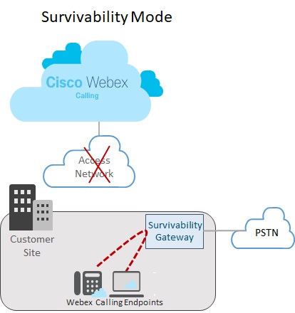
Einrichtung eines einzelnen Standorts
Das folgende Bild zeigt ein Netzwerkausfallszenario, in dem die Verbindung zu Webex unterbrochen ist und die Endpunkte am Webex-Standort im Überlebensmodus arbeiten. Im Bild leitet das Survivability Gateway einen internen Anruf zwischen zwei Endpunkten vor Ort weiter, ohne dass eine Verbindung zu Webex erforderlich ist. In diesem Fall ist das Survivability Gateway mit einer lokalen PSTN-Verbindung konfiguriert. Als Ergebnis können On-Site-Endpunkte im Survivability-Modus das PSTN für eingehende und ausgehende Anrufe an externe Nummern und E911-Anbieter nutzen.
Einrichtung mehrerer Standorte
Das folgende Bild zeigt ein Netzwerkausfallszenario, in dem die Verbindung zu Webex unterbrochen ist und Endpunkte an verschiedenen Standorten im Überlebensmodus arbeiten. Innerhalb des LAN-Netzwerks gibt es mehrere kleinere Standorte, die einem einzigen Survivability-Gateway zugeordnet sind. Diese Bereitstellung optimiert die Auslastung der Gateway-Ressourcen unter Beibehaltung standortspezifischer Konfigurationen für das Anrufrouting.
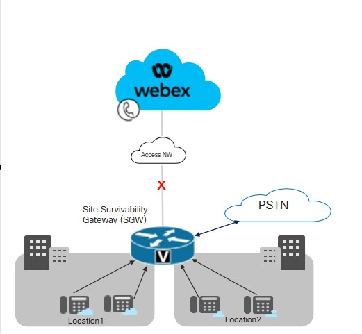
Cisco empfiehlt, für die Konnektivität zwischen dem Survivability Gateway und Endpunkten an verschiedenen Standorten innerhalb eines LANs einen Latenzschwellenwert von 50 Millisekunden einzuhalten.
Wichtige Bedingungen für die Überlebensfähigkeit des Standorts
Für das Survivability Gateway gelten folgende Bedingungen:
-
Die Webex-Cloud enthält die IP-Adresse, den Hostnamen und den Port des Survivability Gateways in der Gerätekonfigurationsdatei. Dadurch können sich die Endpunkte an das Survivability Gateway wenden, um sich zu registrieren, falls die Verbindung zu Webex abbricht.
-
Die tägliche Synchronisierung der Anrufdaten zwischen der Webex-Cloud und dem Survivability Gateway umfasst auch Authentifizierungsinformationen für registrierte Benutzer. Dadurch können Endpunkte sichere Registrierungen aufrechterhalten, selbst wenn sie im Überlebensmodus betrieben werden. Die Synchronisierung umfasst auch Routing-Informationen für diese Benutzer.
-
Das Survivability Gateway kann interne Anrufe automatisch weiterleiten, indem es die von Webex bereitgestellten Routing-Informationen nutzt. Fügen Sie dem Survivability Gateway eine PSTN-Trunk-Konfiguration hinzu, um externe Anrufe zu ermöglichen.
-
Jeder Standort, der Site Survivability einsetzt, benötigt ein Survivability Gateway innerhalb des lokalen Netzwerks.
-
Registrierungen und Anrufsteuerung werden wieder über die Webex-Cloud abgewickelt, sobald die Webex-Netzwerkverbindung für mindestens 30 Sekunden wiederhergestellt ist.
Colocation mit Unified SRST
Das Survivability Gateway unterstützt die gemeinsame Nutzung einer Webex Survivability-Konfiguration und einer Unified SRST-Konfiguration auf demselben Gateway. Das Gateway kann die Ausfallsicherheit sowohl für Webex Calling-Endpunkte als auch für Endpunkte gewährleisten, die sich beim Unified Communications Manager registrieren. So konfigurieren Sie die Colocation:
-
Konfigurieren Sie die Unified SRST-Unterstützung für Endpunkte, die sich beim Unified Communications Manager registrieren. Für die Konfiguration siehe Cisco Unified SRST Administration Guide.
-
Folgen Sie auf demselben Gateway dem Site Survivability Configration Task Flow in diesem Artikel, um das Gateway mit Site Survivability für Webex Calling-Endpunkte zu konfigurieren.
Überlegungen zur Anrufweiterleitung bei der Colocation
Beachten Sie bei der Konfiguration des Anrufroutings für Colocation-Szenarien Folgendes:
-
Das Survivability Gateway leitet interne Anrufe automatisch weiter, vorausgesetzt, beide Endpunkte des Anrufs sind beim Survivability Gateway registriert. Interne Anrufe werden automatisch zwischen allen registrierten Clients (SRST oder Webex Calling) weitergeleitet.
-
Es ist möglich, dass die Verbindung zu einem Anrufsteuerungssystem abbricht, während die Verbindung zum anderen Anrufsteuerungssystem bestehen bleibt. Als Ergebnis registriert sich eine Gruppe von Endpunkten beim Survivability Gateway, während sich eine andere Gruppe von Endpunkten am selben Standort bei der primären Anrufsteuerung registriert. In diesem Fall müssen Sie möglicherweise Anrufe zwischen den beiden Endpunktgruppen über einen SIP-Trunk oder eine PSTN-Leitung weiterleiten.
-
Externe Anrufe und Notrufe (E911) können über einen SIP-Trunk oder eine PSTN-Leitung geleitet werden.
Unterstützte Funktionen und Komponenten
Die folgende Tabelle enthält Informationen zu den unterstützten Funktionen.
| Funktion | MPP-Geräte und Webex-App | VG4xx ATA |
|---|---|---|
|
Anrufe innerhalb des Standorts |
Wird automatisch unterstützt, ohne dass eine spezielle Routing-Konfiguration auf dem Survivability Gateway erforderlich ist. |
Wird automatisch unterstützt, ohne dass eine spezielle Routing-Konfiguration auf dem Survivability Gateway erforderlich ist. Alternative Nummern werden nicht unterstützt. |
|
Standortübergreifende und PSTN-Anrufe (eingehend und ausgehend) |
PSTN-Anrufe basieren auf einer Telefonleitung oder einem SIP-Trunk. |
PSTN-Anrufe basieren auf einer Telefonleitung oder einem SIP-Trunk. |
|
E911-Notrufbearbeitung |
Für Notrufe (E911) wird eine PSTN-Verbindung oder ein SIP-Trunk benötigt. Ausgehende Anrufe verwenden eine spezifische registrierte Notfallstandort-Identifikationsnummer (ELIN) für einen definierten Notfalleinsatzort (ERL). Wenn der Notrufmitarbeiter einen unterbrochenen Anruf zurückruft, leitet das Survivability Gateway den Anruf an das letzte Gerät weiter, das die Notrufnummer gewählt hat. |
Für Notrufe (E911) wird eine PSTN-Verbindung oder ein SIP-Trunk benötigt. Ausgehende Anrufe verwenden eine spezifische registrierte Notfallstandort-Identifikationsnummer (ELIN) für einen definierten Notfalleinsatzort (ERL). Wenn der Notrufmitarbeiter einen unterbrochenen Anruf zurückruft, leitet das Survivability Gateway den Anruf an das letzte Gerät weiter, das die Notrufnummer gewählt hat. |
|
Anruf halten und wieder aufnehmen |
Unterstützt Wenn Sie Wartemusik (Music on Hold, MOH) verwenden, müssen Sie das Survivability Gateway manuell mit einer MOH-Datei bereitstellen. |
VG4xx ATA-Analogleitungen können Anrufe nicht halten oder fortsetzen. Diese Funktion wird nur unterstützt, wenn ein eingehender Anruf über VG4xx ATA empfangen wird. |
|
Anrufweiterleitung |
Unterstützt |
Diese Funktion wird nur unterstützt, wenn ein eingehender Anruf über VG4xx ATA empfangen wird. |
|
Blindes Anrufweiterleiten |
Unterstützt |
Diese Funktion wird nur unterstützt, wenn ein eingehender Anruf über VG4xx ATA empfangen wird. |
|
ID des eingehenden Anrufers (Name) |
Unterstützt |
Unterstützt |
|
Eingehende Anrufer-ID (Name) & Nummer) |
Unterstützt |
Unterstützt |
|
Punkt-zu-Punkt-Videoanruf |
Unterstützt |
Nicht unterstützt |
|
Dreierkonferenz |
Nicht unterstützt |
Nicht unterstützt |
|
Gemeinsam genutzte Leitungen |
Unterstützt |
Unterstützt |
|
Virtuelle Leitungen |
Unterstützt |
Nicht unterstützt |
|
Rufumleitung |
Unterstützt für Rufumleitung an alle, Nicht antworten und Besetzt. |
Unterstützt |
|
Sammelanschlussgruppe |
Unterstützt für Folgendes: Sequenziell, Parallel, Gleichgestellt und Längste Leerlaufzeit. |
Unterstützt |
|
Auto Attendant |
Unterstützt für Wählverbindungen über Nebenstellen |
Unterstützt |
Nach der Konfiguration des Features ist Site Survivability für die folgenden unterstützten Endpunkte verfügbar.
| Typ | Modelle | Mindestversion |
|---|---|---|
| Cisco IP-Telefon mit Multiplattform-Firmware (MPP) |
6821, 6841, 6851, 6861, 6861 WLAN, 6871 7811, 7821, 7841, 7861 8811, 8841, 8851, 8861 8845 (nur Audio), 8865 (nur Audio), 8875 (Video) 9800 Weitere Informationen zu unterstützten Cisco IP-Telefonen mit Multiplattform-Firmware (MPP) finden Sie unter: |
12.0(1) Für 8875-Telefone – Phone OS 3.2 und spätere Versionen Für die 9800er-Serie – PhoneOS 3.2(1) |
|
Cisco IP Conference Phone |
7832, 8832 |
12.0(1) |
|
Cisco Webex-App |
Windows,Mac |
43.2 |
|
Analoge Endpunkte |
VG400 ATA, VG410 ATA und VG420 ATA Cisco ATA 191 und 192 |
17.16.1a 11.3(1) für ATA 191 und 192 |
Geräte von Drittanbietern werden von Survivability Gateway nicht unterstützt.
Die folgende Tabelle hilft bei der Konfiguration von Cisco IOS XE-Routern als Survivability Gateway. Diese Tabelle listet die maximale Anzahl von Endpunkten auf, die jede Plattform unterstützt, sowie die minimale IOS XE-Version.
Die Webex Calling Survivability Gateway-Funktionen sind ab Cisco IOS XE Dublin Version 17.12.3 verfügbar. Die Funktionen Hunt Group, Rufumleitung und automatische Telefonzentrale sind ab iOS 17.18.2 und späteren Versionen verfügbar.
| Modell | Maximale Anzahl an Endpunktregistrierungen | Mindestversion |
|---|---|---|
|
Integrated Services Router 4321 | 50 |
Cisco IOS XE Dublin 17.12.3 oder spätere Versionen |
|
Integrierter Dienstrouter 4331 | 100 | |
|
Integrated Services Router 4351 | 700 | |
|
Integrated Services Router 4431 | 1200 | |
|
Integrated Services Router 4451-X | 2000 | |
|
Integrated Services Router 4461 | 2000 | |
|
Catalyst Edge 8200L-1N-4T | 1500 | |
|
Catalyst Edge 8200-1N-4T | 2500 | |
|
Catalyst Edge 8300-1N1S-6T | 2500 | |
|
Catalyst Edge 8300-2N2S-6T | 2500 | |
|
Catalyst Edge 8300-1N1S-4T2X | 2500 | |
|
Catalyst Edge 8300-2N2S-4T2X | 2500 | |
|
Catalyst Edge 8000V Software kleine Konfiguration | 500 | |
|
Catalyst Edge 8000V Software-Medium-Konfiguration | 1000 | |
|
Catalyst Edge 8000V Software große Konfiguration | 2000 |
Portreferenzinformationen für das Survivability Gateway
|
Zweck der Verbindung: |
Quelladressen |
Quellports |
Protokoll |
Zieladressen |
Zielports |
|---|---|---|---|---|---|
|
Anrufsignalisierung an das Survivability Gateway (SIP TLS) |
Geräte |
5060-5080 |
TLS |
Survivability Gateway |
8933 |
|
Medien an das Survivability Gateway (SRTP) anrufen |
Geräte |
19560-19660 |
UDP |
Survivability Gateway |
8000-14198 (SRTP über UDP) |
|
Anrufsignalisierung an das PSTN-Gateway (SIP) |
Survivability Gateway |
Kurzlebig |
TCP oder UDP |
Ihr ITSP PSTN-Gateway |
5060 |
|
Anrufmedien an PSTN-Gateway (SRTP) |
Survivability Gateway |
8000-48198 |
UDP |
Ihr ITSP PSTN-Gateway |
Kurzlebig |
|
Zeitsynchronisation (NTP) |
Survivability Gateway |
Kurzlebig |
UDP |
NTP-Server |
123 |
|
Namensauflösung (DNS) |
Survivability Gateway |
Kurzlebig |
UDP |
DNS-Server |
53 |
|
Cloud-Management |
Konnektor |
Kurzlebig |
HTTPS |
Webex-Dienste |
443, 8433 |
Hinweise zur Bedienung des Cloud-Modus finden Sie im Hilfeartikel Port Reference Information for Webex Calling.
Sie können die Port-Einstellungswerte auf Cisco IOS XE-Routern anpassen. Diese Tabelle verwendet Standardwerte als Orientierungshilfe.
Funktionskonfiguration
Aufgabenablauf zur Konfiguration der Standortüberlebensfähigkeit
Führen Sie die folgenden Aufgaben aus, um die Standortausfallsicherheit für einen bestehenden Webex Calling-Standort zu erhöhen. Falls die Verbindung zur Webex-Cloud abbricht, kann ein Survivability Gateway im lokalen Netzwerk die Anrufsteuerung für Endpunkte an diesem Standort übernehmen.
Vorbereitungen
Wenn Sie ein neues Gateway als Survivability Gateway bereitstellen müssen, lesen Sie den Webex-Artikel Cisco IOS Managed Gateways bei Webex Cloud registrieren, um das Gateway zum Control Hub hinzuzufügen.
| Schritte | Befehl oder Aktion | Zweck |
|---|---|---|
|
1 | Weisen Sie einem Gateway einen Ausfallsicherheitsdienst zu. |
Weisen Sie im Control Hub den Dienst Survivability Gateway einem Gateway zu. |
|
2 | Konfigurationsvorlage herunterladen |
Laden Sie die Konfigurationsvorlage aus dem Control Hub herunter. Sie benötigen die Vorlage, wenn Sie die Gateway-Befehlszeile konfigurieren. |
|
3 |
Lizenzen für das Survivability Gateway konfigurieren. | |
|
4 |
Konfigurieren Sie Zertifikate für das Survivability Gateway. | |
|
5 |
Verwenden Sie die zuvor heruntergeladene Konfigurationsvorlage als Leitfaden für die Konfiguration der Gateway-Befehlszeile. Führen Sie alle im Template enthaltenen obligatorischen Konfigurationen durch. |
Weisen Sie einem Gateway einen Ausfallsicherheitsdienst zu.
Vorbereitungen
| 1 |
Gehen Sie unter ] Services [ auf ] Calling [und klicken Sie dann auf die Registerkarte Managed Gateways. Die Ansicht „Verwaltete Gateways“ zeigt die Liste der Gateways an, die Sie über Control Hub verwalten.
|
| 2 |
Wählen Sie das Gateway aus, das Sie als Survivability Gateway zuweisen möchten, und wählen Sie basierend auf dem Wert des Feldes Service einen der folgenden Einträge aus:
|
| 3 |
Wählen Sie im Dropdown-Menü „Diensttyp“ die Option „ Survivability Gateway “ aus und füllen Sie die folgenden Felder aus:
Sobald Sie die Registrierung abgeschlossen haben, werden die Standortdetails auf der Seite „Verwaltete Gateways“ angezeigt. |
| 4 |
Klicken Sie auf Zuweisen. Die Ansicht „Verwaltete Gateways“ zeigt die Liste der Standorte an, die dem Gateway zugewiesen sind.
|
Konfigurationsvorlage herunterladen
Lizenzierung konfigurieren
| 1 |
Wechseln Sie auf dem Router in den globalen Konfigurationsmodus: |
| 2 |
Konfigurieren Sie Lizenzen mithilfe der Befehle, die nur für Ihre spezifische Plattform gelten.
Bei der Konfiguration eines Durchsatzes von mehr als 250 Mbit/s benötigen Sie eine HSEC-Plattformlizenz. |
Zertifikate konfigurieren
Konfigurieren von Zertifikaten auf Cisco IOS XE
Führen Sie die folgenden Schritte aus, um Zertifikate für das Survivability Gateway anzufordern und zu erstellen. Verwenden Sie Zertifikate, die von einer öffentlich bekannten Zertifizierungsstelle unterzeichnet wurden.
Die Survivability Gateway-Plattform unterstützt ausschließlich öffentlich bekannte CA-Zertifikate. Private oder unternehmensweite CA-Zertifikate können nicht für Survivability Gateway verwendet werden.
Eine Liste der für Webex Calling unterstützten Stammzertifizierungsstellen finden Sie unter Welche Stammzertifizierungsstellen werden für Anrufe an Cisco Webex Audio- und Videoplattformen unterstützt?.
Die Survivability Gateway-Plattform unterstützt keine Wildcard-Zertifikate.
Führen Sie die Befehle aus dem Beispielcode aus, um die Schritte abzuschließen. Weitere Informationen zu diesen Befehlen sowie zu zusätzlichen Konfigurationsoptionen finden Sie im Kapitel „ SIP TLS Support“ im Cisco Unified Border Element Configuration Guide.
| 1 |
Wechseln Sie in den globalen Konfigurationsmodus, indem Sie die folgenden Befehle ausführen: |
| 2 |
Generieren Sie den privaten RSA-Schlüssel, indem Sie den folgenden Befehl ausführen. Der Modulus des privaten Schlüssels muss mindestens 2048 Bit lang sein. |
| 3 |
Konfigurieren Sie einen Vertrauenspunkt, der das Survivability Gateway-Zertifikat speichert. Der vollqualifizierte Domänenname (FQDN) des Gateways muss denselben Wert haben, den Sie bei der Zuweisung des Survivability-Dienstes zum Gateway verwendet haben. |
| 4 |
Generieren Sie eine Zertifikatsignierungsanforderung durch Ausführen des Befehls Geben Sie bei Aufforderung Nachdem die CSR auf dem Bildschirm angezeigt wird, kopieren Sie das Zertifikat mit Notepad in eine Datei, die Sie an eine unterstützte Zertifizierungsstelle (CA) senden können. Falls Ihr Zertifikatssignierungsanbieter eine CSR im PEM-Format (Privacy Enhanced Mail) verlangt, fügen Sie vor dem Absenden eine Kopf- und Fußzeile hinzu. Beispiel: |
| 5 |
Nachdem Ihnen die Zertifizierungsstelle ein Zertifikat ausgestellt hat, führen Sie den Befehl Fügen Sie bei Aufforderung die Base64-Zeichenkette ein. CER/PEM Ausgabe des CA-Zertifikatsinhalts (nicht des Gerätezertifikats) an das Terminal. |
| 6 |
Importieren Sie das signierte Hostzertifikat mithilfe des Befehls Fügen Sie bei Aufforderung die Base64-Zeichenkette ein. CER/PEM Zertifikat in das Terminal einlesen. |
| 7 |
Prüfen Sie, ob das Stammzertifikat der Zertifizierungsstelle verfügbar ist: Die Webex Calling-Lösung unterstützt ausschließlich öffentlich bekannte Zertifizierungsstellen. Private oder unternehmensweite CA-Zertifikate werden nicht unterstützt. |
| 8 |
Falls Ihr Stammzertifikat nicht im Paket enthalten ist, beschaffen Sie sich das Zertifikat und importieren Sie es in einen neuen Vertrauenspunkt. Führen Sie diesen Schritt durch, wenn für Ihr Cisco IOS XE-Gateway kein öffentlich bekanntes Stammzertifikat einer Zertifizierungsstelle verfügbar ist. Fügen Sie bei Aufforderung die Base64-Zeichenkette ein. CER/PEM Zertifikatsinhalte in das Terminal einlesen. |
| 9 |
Im Konfigurationsmodus können Sie mit den folgenden Befehlen den Standard-Vertrauenspunkt, die TLS-Version und die SIP-UA-Standardeinstellungen festlegen. |
Importieren Sie Zertifikate zusammen mit Schlüsselpaaren
Sie können CA-Zertifikate und Schlüsselpaare als Paket im PKCS12-Format (.pfx oder .p12) importieren. Sie können das Paket von einem lokalen Dateisystem oder einem Remote-Server importieren. PKCS12 ist ein spezielles Zertifikatsformat. Es bündelt die gesamte Zertifikatskette vom Stammzertifikat bis zum Identitätszertifikat zusammen mit dem RSA-Schlüsselpaar. Das heißt, das von Ihnen importierte PKCS12-Paket würde das Schlüsselpaar, die Hostzertifikate und die Zwischenzertifikate enthalten. Importieren Sie ein PKCS12-Bundle für die folgenden Szenarien:
-
Exportieren Sie Daten von einem anderen Cisco IOS XE-Router und importieren Sie sie in Ihren Survivability Gateway-Router.
-
Generierung des PKCS12-Bundles außerhalb eines Cisco IOS XE-Routers mit OpenSSL
Führen Sie die folgenden Schritte aus, um Zertifikate und Schlüsselpaare für Ihren Survivability Gateway-Router zu erstellen, zu exportieren und zu importieren.
| 1 |
(Optional) Exportieren Sie das für Ihren Survivability Gateway-Router erforderliche PKCS12-Bundle. Dieser Schritt ist nur dann erforderlich, wenn Sie von einem anderen Cisco IOS XE-Router exportieren. |
| 2 |
(Optional) Erstellen Sie ein PKCS12-Bundle mit OpenSSL. Dieser Schritt ist nur dann anwendbar, wenn Sie ein PKCS12-Bundle außerhalb von Cisco IOS XE mit OpenSSL generieren. |
| 3 |
Importieren Sie das Dateipaket im PKCS12-Format. Nachfolgend finden Sie eine Beispielkonfiguration für den Befehl sowie Details zu den konfigurierbaren Parametern:
Der Befehl crypto pki import erstellt automatisch den Trustpoint, um das Zertifikat aufzunehmen. |
| 4 |
Im Konfigurationsmodus können Sie mit den folgenden Befehlen den Standard-Vertrauenspunkt, die TLS-Version und die SIP-UA-Standardeinstellungen festlegen. |
Konfigurieren des Überlebensfähigkeitsgateways
Gateway als Überlebensfähigkeitsgateway konfigurieren
Verwenden Sie die zuvor heruntergeladene Konfigurationsvorlage als Leitfaden für die Konfiguration der Gateway-Befehlszeile. Nehmen Sie die obligatorischen Konfigurationen in der Vorlage vor.
Die folgenden Schritte enthalten Beispielbefehle sowie eine Erläuterung der Befehle. Passen Sie die Einstellungen an Ihre Einsatzumgebung an. Die spitzen Klammern (z. B. ) kennzeichnen Einstellungen, in die Sie Werte eingeben sollten, die für Ihre Bereitstellung gelten. Die verschiedenen <tag> Einstellungen verwenden numerische Werte, um Konfigurationssätze zu identifizieren und zuzuordnen.
- Sofern nicht anders angegeben, ist für diese Lösung die Durchführung aller Konfigurationen in diesem Verfahren erforderlich.
- Wenn Sie Einstellungen aus der Vorlage anwenden, ersetzen Sie
%tokens%durch Ihre bevorzugten Werte, bevor Sie diese auf das Gateway kopieren. - Weitere Informationen zu den Befehlen finden Sie in der Webex Managed Gateway Befehlsreferenz. Verwenden Sie diese Anleitung, es sei denn, die Befehlsbeschreibung verweist auf ein anderes Dokument.
| 1 |
Wechseln Sie in den globalen Konfigurationsmodus. Hierbei gilt:
|
| 2 |
Führen Sie die Konfigurationen des Sprachdienstes durch:
Erläuterung der Befehle:
|
| 3 |
Aktivieren Sie die Ausfallsicherheit auf dem Router: Erläuterung der Befehle:
|
| 4 |
NTP-Server konfigurieren:
|
| 5 |
(Optional). Allgemeine Berechtigungen für den Aufruf der Einschränkungsklasse konfigurieren: Das vorhergehende Beispiel erstellt eine Reihe von benutzerdefinierten Einschränkungsklassen, die Kategorien genannt werden (zum Beispiel |
| 6 |
Konfigurieren Sie eine Liste bevorzugter Codecs. Die folgende Liste gibt beispielsweise g711ulaw als bevorzugten Codec an, gefolgt von g711alaw. Erläuterung der Befehle:
|
| 7 |
Standard-Sprachregisterpools konfigurieren: Erläuterung der Befehle:
|
| 8 |
Notruf konfigurieren: Erläuterung der Befehle:
Wenn das Wi-Fi-Overlay nicht genau mit den IP-Subnetzen übereinstimmt, dann verfügt die Notrufzentrale für mobile Geräte möglicherweise nicht über die korrekte ELIN-Zuordnung. |
| 9 |
Konfigurieren Sie Wählverbindungen für das PSTN. Ein Beispiel für die Konfiguration des Dial-Peers finden Sie unter PSTN-Verbindungsbeispiele. |
| 10 |
Optional. Aktivieren Sie die Wartemusik für den Router. Sie müssen eine Musikdatei im G.711-Format im Flash-Speicher des Routers speichern. Die Datei kann im .au- oder .wav-Dateiformat vorliegen, muss aber 8-Bit-8-kHz-Daten enthalten (z. B. das ITU-T A-law- oder mu-law-Datenformat). Erläuterung der Befehle:
|
Vollständige Synchronisierung auf Abruf.
Optional. Führen Sie diese Prozedur nur durch, wenn Sie eine sofortige Synchronisierung auf Abruf durchführen möchten. Dieses Verfahren ist nicht zwingend erforderlich, da die Webex-Cloud die Anrufdaten einmal täglich automatisch mit dem Survivability Gateway synchronisiert.
Eigenschaften des Überlebensfähigkeitsgateways bearbeiten
| 1 |
Melden Sie sich bei Control Hub an. Wenn Sie eine Partnerorganisation sind, wird der Partner Hub gestartet. Um den Control Hub zu öffnen, klicken Sie im Partner Hub auf die Ansicht Kunde und wählen Sie den entsprechenden Kunden aus, oder wählen Sie Meine Organisation, um die Control Hub-Einstellungen für die Partnerorganisation zu öffnen. |
| 2 |
Gehen Sie zu . |
| 3 |
Klicken Sie auf das entsprechende Survivability Gateway, um die Ansicht Survivability Service für dieses Gateway zu öffnen. |
| 4 |
Klicken Sie auf die Schaltfläche Bearbeiten und aktualisieren Sie die Einstellungen für Folgendes.
|
| 5 |
Klicken Sie auf Senden. Wenn Sie ein Survivability Gateway aus Control Hub löschen möchten, heben Sie zuerst die Zuweisung des Dienstes Survivability Gateway auf. Weitere Details finden Sie unter Dienste verwalteten Gateways zuweisen. |
Konfigurationen zur Aktivierung von CDRs auf dem Survivability-Gateway
Der Konnektor konfiguriert automatisch CDR-bezogene Befehle, um die Erfassung von Anrufzählungsmetriken zu erleichtern.
Am Ende eines Überlebensfähigkeitsereignisses verarbeitet der Konnektor die während des Ereigniszeitraums generierten CDRs zusammen mit den Konfigurationsdaten, um verschiedene Anrufanzahlen zu ermitteln. Zu den Kennzahlen gehören die Anzahl der Gesamtanrufe, Notrufe und externen Anrufe. Sie dienen der Überwachung der Nutzung interner Funktionen. Lediglich die Anrufanzahlmetriken werden an die Webex-Cloud gesendet, die eigentlichen CDRs werden jedoch nicht übertragen.
Nachfolgend ein Beispiel für eine Konfiguration:
!
gw-accounting file
primary ifs bootflash:guest-share/cdrs/
acct-template callhistory-detail
maximum cdrflush-timer 5
cdr-format detailed
!
Erläuterung der Befehle:
-
primary ifs bootflash:guest-share/cdrs/- Dieser Befehl dient dazu, die CDR-Dateien im Ordner „guest-share“ zu speichern, um dem Connector den Zugriff zu ermöglichen. -
acct-template callhistory-detail- Dieser Befehl ist erforderlich, um das Dial-Peer-Tag in den CDR aufzunehmen. -
maximum cdrflush-timer 5- Der Standardwert beträgt 60 Minuten, aber durch die Einstellung auf 5 Minuten können CDRs schneller in der Datei protokolliert werden. -
cdr-format detailed- Dies ist das Standardformat. Das kompakte Format ist ungeeignet, da es das Dial-Peer-Tag nicht enthält.
Konfigurationen zur Aktivierung der Anrufweiterleitung
Die Anrufweiterleitungsfunktion ist Teil der Ausfallsicherheitsfunktionen, die eine kontinuierliche Anrufbearbeitung bei Netzwerkausfällen gewährleisten, wenn die Verbindung zur Webex-Cloud unterbrochen wird. Das Survivability-Gateway fungiert als lokales Fallback-Gateway, das es Endpunkten ermöglicht, sich lokal zu registrieren und wichtige Anruffunktionen aufrechtzuerhalten.
-
Das Anrufweiterleitungsverhalten im Survivability-Modus wird vom Survivability-Gateway mithilfe von Pool-Konfigurationen, Dial-Peer-Konfigurationen und Routing-Richtlinien verwaltet, die Anrufe lokal bearbeiten oder über PSTN- oder SIP-Trunks weiterleiten.
-
Das Survivability-Gateway deaktiviert SIP REFER, SIP moved-temporarily für Anrufweiterleitung und Anruftransfer-Zusatzdienste, da Webex Calling diese Methoden im Survivability-Modus nicht verwendet.
Konfigurieren von Sprachregisterpools für Rufumleitungsszenarien:
|
Um die Rufumleitungsfunktion zu nutzen, konfigurieren Sie den Befehl
|
Konfigurationen zur Aktivierung der Jagdgruppe
Diese Tabelle bietet eine Zuordnung für die Konfiguration der Jagdgruppenfunktion in Control Hub und die Verwendung der Survivability-Gateway-Befehle.
| Merkmale der Jagdgruppe | Konfiguration über den Control Hub | Befehle des Überlebensfähigkeits-Gateways |
|---|---|---|
|
Anrufweiterleitungsmuster auswählen |
Top-Down/Simultaneous/Circular/Longest-idle | Sequential/Parallel/Peer/Longest-idle |
|
Jagdgruppe hinzufügen |
Fügen Sie pro Standort eine Jagdgruppe mit Namen und Telefonnummer hinzu. | Um eine Jagdgruppe hinzuzufügen, verwenden Sie die voice hunt-group . Fügen Sie anschließend die Telefonnummer mit dem Befehl pilot und den Namen der Anrufgruppe mit dem Befehl description hinzu. |
|
Benutzer, Arbeitsbereiche oder virtuelle Leitungen zum Hinzufügen auswählen |
Wählen Sie die Agenten aus, die Teil der Jagdgruppe sein sollen. |
Konfigurieren Sie die Liste der Agenten mithilfe des Befehls |
|
Weiterleitung nach bestimmter Anzahl von Klingelzeichen |
Konfigurieren Sie dies mithilfe der Option Anzahl der Ringe festlegen |
Konfigurieren Sie die Weiterleitung des Anrufs an den nächsten Agenten mithilfe des Befehls |
|
Weiterleiten, wenn besetzt |
Konfigurieren Sie dies mithilfe der Option Weiter bei belegtem Standort . |
Konfigurieren Sie mit dem Befehl |
|
Anrufe umleiten, wenn alle Agenten nicht erreichbar | Konfigurieren Sie dies mithilfe der Option Anrufe umleiten, wenn alle Agenten nicht erreichbar sind |
Konfigurieren Sie mit dem Befehl |
|
Anrufe umleiten, wenn alle Agenten beschäftigt sind oder die Sammelanschlussgruppe besetzt ist |
Konfigurieren Sie dies mithilfe der OptionAnrufe umleiten, wenn alle Agenten oder die Anrufgruppe belegt sind |
Konfigurieren mit |
-
Konfigurieren Sie sequentielle Ringe einer Jagdgruppe.
voice hunt-group 1 sequential pilot 1111 number 1 1001 number 2 1002 number 3 7089001 number 4 7089002 number 5 +1210903443 ..... ..... timeout 20 final 1009 statistics collect description present-call idle-phone -
Konfigurieren einer Jagdgruppe paralleler Ringe
voice hunt-group 2 parallel pilot 2222 number 1 2001 number 2 2002 number 3 2089001 number 4 2089002 number 5 +12109034433 ..... ..... timeout 60 final 1009 statistics collect description
Beschreibung der Befehle:
-
voice hunt-group- Mit diesem Befehl wird der Konfigurationsmodus für eine Jagdgruppe definiert und aufgerufen. -
parallel- Dieses Schlüsselwort legt die Methode oder den Algorithmus der Anrufgruppe fest, mit dem das System eingehende Anrufe an die Mitglieder dieser Anrufgruppe verteilt. -
number- Erstellt eine Liste von extensions/e164 numbers/ESN die Mitglieder einer Stimmenjagdgruppe sind. Keine der in der Liste aufgeführten Nummern darf die Pilotennummer einer anderen Jagdgruppe sein. -
pilot- Dies ist die Hauptnummer oder Rufnummer für die Anrufgruppe. Anrufer wählen diese Nummer, um die Jagdgruppe zu erreichen. -
timeout- Legt die maximale Zeitspanne in Sekunden fest, die die Suchgruppe versucht, ihre Mitglieder anzurufen, bevor sie die nächste Aktion ausführt. -
final- Dieser Befehl legt die Ausweichnummer fest. -
statistics collect- Ermöglicht die Erfassung von operativen Statistiken für die Jagdgruppe. -
descriptin- Beschreibung der Jagdgruppe -
present-call idle-phone-Leiten Sie den Anruf nur an Agenten weiter, die gerade keine Zeit haben.
Nachfolgend ein Beispiel der Ausgabe des Befehls show voice hunt-group statistics. Die Ausgabe umfasst Direktanrufe an eine Rufnummerngruppe und Anrufe aus der Warteschlange oder dem B-ACD.
Router# show voice hunt-group 1 statistics last 1 h
Wed 04:00 - 05:00
Max Agents: 3
Min Agents: 3
Total Calls: 9
Answered Calls: 7
Abandoned Calls: 2
Average Time to Answer (secs): 6
Longest Time to Answer (secs): 13
Average Time in Call (secs): 75
Longest Time in Call (secs): 161
Average Time before Abandon (secs): 8
Calls on Hold: 2
Average Time in Hold (secs): 16
Longest Time in Hold (secs): 21
Per agent statistics:
Agent: 5012
From Direct Call:
Total Calls Answered: 3
Average Time in Call (secs): 70
Longest Time in Call (secs): 150
Totals Calls on Hold: 1
Average Hold Time (secs): 21
Longest Hold Time (secs): 21
From Queue:
Total Calls Answered: 3
Average Time in Call (secs): 55
Longest Time in Call (secs): 78
Total Calls on Hold: 2
Average Hold Time (secs): 19
Longest Hold Time (secs): 26
Total Loged in Time (secs): 3000
Total Loged out Time (secs): 600
Agent: 5013
From Direct Call:
Total Calls Answered: 3
Average Time in Call (secs): 51
Longest Time in Call (secs): 118
Totals Calls on Hold: 1
Average Hold Time (secs): 11
Longest Hold Time (secs): 11
From Queue:
Total Calls Answered: 1
Average Time in Call (secs): 4
Longest Time in Call (secs): 4
Total Loged in Time (secs): 3000
Total Loged out Time (secs): 600
Agent: 5014
From Direct Call:
Total Calls Answered: 1
Average Time in Call (secs): 161
Longest Time in Call (secs): 161
From Queue:
Total Calls Answered: 1
Average Time in Call (secs): 658
Longest Time in Call (secs): 658
Total Loged in Time (secs): 3000
Total Loged out Time (secs): 600
Queue related statistics:
Total calls presented to the queue: 5
Calls handoff to IOS: 5
Number of calls in the queue: 0
Average time to handoff (secs): 2
Longest time to handoff (secs): 3
Number of abandoned calls: 0
Average time before abandon (secs): 0
Calls forwarded to voice mail: 0
Calls answered by voice mail: 0
Number of error calls: 0
Router# sh voice hunt-group
Group 1
type: sequential
pilot number: 4444, peer-tag 2147483647
list of numbers:
Member Used-by State Login/Logout
====== ======= ===== ============
1001 1001 up -
1003 1003 up -
preference: 0
preference (sec): 0
timeout: 15
final_number:
auto logout: no
stat collect: no
phone-display: no
hlog-block: no
calls in queue: 0
overwrite-dyn-stats: no
members logout: no
present-call idle-phone: no
webex-sgw-bgl14#
Konfigurationen zur Aktivierung der automatischen Basis-Anrufverteilung (B-ACD)
Der Basic Automatic Call Distribution (B-ACD) und Auto Attendant (AA) Service bietet die automatische Beantwortung von Anrufen von außen mit Begrüßungen und Menüs, die es den Anrufern ermöglichen, die richtige Abteilung auszuwählen oder bekannte Durchwahlnummern zu wählen.
B-ACD bietet automatische Anrufannahme und Anrufverteilung über interaktive Menüs und lokale Rufgruppen. Die B-ACD-Anwendung besteht aus automatischen Vermittlungsdiensten (AA) und einem Anrufwarteschlangendienst. Die automatische Telefonzentrale B-ACD unterstützt PSTN-Anrufe, die mit dem eingehenden SIP-Trunk und dem Codec g711ulaw ausgehandelt werden.
B-ACD unterstützt Sprachsuchgruppen mit sequenzieller, paralleler, gleichrangiger und längster Leerlauf-Anruf-Blast-Unterstützung sowie SIP Shared Lines und Mixed Shared Lines.
Ein eingehender Anruf wählt die B-ACD AA-Pilotnummer und gibt eine Ansage von sich, die eine Begrüßung und Anweisungen enthält, die dem Anrufer helfen, den Anruf automatisch weiterzuleiten.
Beschränkungen
Verwenden Sie beim Weiterleiten von Anrufen denselben Codec auf den eingehenden und ausgehenden Wählverbindungen. Die Verwendung unterschiedlicher Codecs wird nicht unterstützt. IOS ruft für die von einer TCL-Anwendung verarbeiteten Aufrufe keinen Transcoder auf.
B-ACD-Komponenten
Die B-ACD-Anwendung besteht aus einem Anrufwarteschlangendienst und einem oder mehreren AA-Diensten. Die konfigurierbaren Komponenten dieser Dienste sind:
-
Pilotnummer
-
Begrüßungsansage und andere Audiodateien
-
Menü-Optionen
-
Durchwahl anwählen
Pilotnummer
Jeder AA-Service hat seine eigene AA-Pilotnummer, die Anrufer wählen, um den AA zu erreichen. Diese Zahl wird im Befehl param aa-pilot angegeben. Die AA-Pilotnummer ist keiner Agenten-Telefonnummer oder einem physischen Telefon zugeordnet. Sie müssen jedoch einen Dial-Peer definieren, bei dem die AA-Pilotnummer als eingehende Rufnummer angegeben ist, damit diese Nummer von externen Anrufern erreicht werden kann.
Begrüßungsansage und andere Audiodateien
Die Begrüßungsansage ist eine Audiodatei, die abgespielt wird, wenn ein Anruf von der Pilotennummer angenommen wird. Diese Audiodatei ist eine von mehreren Audiodateien, die im Rahmen des B-ACD-Dienstes verwendet werden, um Anrufer über ihren Status und mögliche Handlungsoptionen zu informieren. Sie können personalisierte Audiodateien erstellen, in denen die Ihren Anrufern zur Verfügung stehenden Menüoptionen beschrieben werden. B-ACD-Audiodateien werden in den folgenden Abschnitten beschrieben:
Standard-Audiodateien neu aufnehmen
Für jeden Punkt im Skript werden Standard-Audiodateien bereitgestellt und den Anrufern zur Verfügung gestellt. Sie laden die Standard-Audiodateien über den Link herunter und kopieren sie an einen Ort, der vom B-ACD-Router erreicht werden kann, z. B. auf einen Flash-Speicher oder einen TFTP-Server. Die Audiodateien und die Skriptdateien sind in einer TAR-Datei auf der Website zusammengefasst. Die Standarddateien und ihre Meldungen sind in der Tabelle aufgeführt. Sie können personalisierte Nachrichten über die Standardnachrichten neu aufnehmen, aber Sie können die Namen der Audiodateien nicht ändern, außer wie im Abschnitt Ändern von Sprachcodes und Dateinamenausdrücklich beschrieben.
Um die Standard-Audioansagen vor der erstmaligen Verwendung eines B-ACD-Dienstes neu aufzunehmen und zu installieren, folgen Sie den Schritten im Abschnitt Herunterladen von Tcl-Skripten und Audioansagen. Um Audioansagen in einem bestehenden B-ACD-Dienst neu aufzunehmen, befolgen Sie die Schritte im Abschnitt Aktualisieren von Skriptparametern und Audioansagen (Nur Wahl über Nebenstelle).
| Standarddateiname | Standardansage | Länge der Standardankündigung |
|---|---|---|
en_bacd_welcome.au |
"Vielen Dank für den Anruf." Beinhaltet eine zweisekündige Pause nach der Nachricht. |
3 Sekunden |
en_bacd_options_menu.au |
Für Verkaufsanfragen 1 drücken (Pause) Für Kundendienst bitte 2 drücken (Pause). Um über die Durchwahl zu wählen, drücken Sie 3 (Pause). Um mit einem Mitarbeiter zu sprechen, drücken Sie die Null. Beinhaltet eine viersekündige Pause nach der Nachricht. |
15seconds |
en_bacd_disconnect.au |
„Wir können Ihren Anruf momentan nicht entgegennehmen.“ Versuchen Sie es zu einem späteren Zeitpunkt erneut. Vielen Dank für den Anruf." Beinhaltet eine viersekündige Pause nach der Nachricht. |
10seconds |
en_bacd_invalidoption. au |
„Sie haben eine ungültige Option eingegeben.“ Bitte versuchen Sie es erneut. Beinhaltet eine einsekündige Pause nach der Nachricht. Diese Ansage wird abgespielt, wenn ein Anrufer eine ungültige Menüoption auswählt oder eine ungültige Durchwahl wählt. |
7seconds |
en_bacd_enter_dest.au |
„Bitte geben Sie die gewünschte Durchwahlnummer ein.“ Beinhaltet eine fünfsekündige Pause nach der Nachricht. Diese Ansage wird abgespielt, wenn ein Anrufer die Option |
7seconds |
en_bacd_allagentsbusy. au |
„Alle Mitarbeiter sind derzeit mit der Betreuung anderer Kunden beschäftigt.“ Bitte bleiben Sie in der Leitung, um Unterstützung zu erhalten. Jemand wird in Kürze bei Ihnen sein.“ Beinhaltet eine zweisekündige Pause nach der Nachricht. Diese Aufforderung wird auch als zweite Begrüßung bezeichnet. |
7seconds |
en_bacd_music_on_hol d.au |
Für Anrufer mit B-ACD wird Wartemusik (MOH) abgespielt. |
60seconds |
Falls Sie eine der Audiodateien neu aufnehmen, beachten Sie bitte, dass die B-ACD-Ansagen eine G.711-Audiodatei (.au) mit 8-Bit-, Mu-Law- und 8-kHz-Codierung erfordern. Wir empfehlen die folgenden Audio-Tools oder andere von vergleichbarer Qualität:
-
Adobe Audition für Microsoft Windows von Adobe Systems Inc. (ehemals Cool Edit von Syntrillium Software Corp.)
-
AudioTool für Solaris von Sun Microsystems Inc.
B-ACD konfigurieren
Hier einige Konfigurationsbeispiele:
application
service aa bootflash:app-b-acd-aa-3.0.0.8.tcl
paramspace english index 1
param handoff-string aa
param dial-by-extension-option
paramspace english language en
param aa-pilot
paramspace english location flash:
param welcome-prompt _bacd_welcome.au
param voice-mail
param service-name queue
!
service queue bootflash:app-b-acd-3.0.0.8.tcl
param queue-len 30
param queue-manager-debugs 1
!
! SIP PSTN Dial-Peers for Auto Attendant(BACD) service called aa associated with incoming voice port
dial-peer voice 500 voip
description Inbound dial-peer for Auto Attendant
service aa
session protocol sipv2
incoming called-number
dtmf-relay rtp-nte
codec g711ulaw
no vad
!
! TDM PSTN Dial-Peers if not using SIP for Auto Attendant(BACD) service called aa associated with incoming voice pots
dial-peer voice 500 voip
description Inbound dial-peer for Auto Attendant
service aa
incoming called-number
port %tdm_port%
! | Befehl | Erklärung |
|---|---|
param dial-by-extension-option |
Ermöglicht es Anrufern, nach dem Wählen der angegebenen Menünummer Durchwahlnummern anzurufen. Menünummer— Kennung einer Menüoption. Die Skala reicht von 1 bis 9. Es gibt keinen Standardwert. |
param aa-pilot |
Gibt die Pilotennummer an, die dem automatischen Vermittlungsdienst zugeordnet ist. |
param voice-mail |
Definiert ein alternatives Ziel für Anrufe, die von AA-Agenten nicht entgegengenommen werden. |
paramspace english language en |
Definiert den Sprachcode von Audiodateien, die von einer IVR-Anwendung für dynamische Ansagen verwendet werden.
Dieser Sprachcode muss mit dem zweistelligen Sprachpräfix übereinstimmen, das in den Namen Ihrer Audio-Prompt-Dateien verwendet wird, unabhängig von der Sprache, die tatsächlich in der Datei verwendet wird. Weitere Informationen finden Sie in der Begrüßungsansage und den anderen Audiodateien |
param welcome-prompt
audio-filename |
Weist eine Audiodatei für die Begrüßungsansage dieses AA-Dienstes zu.
|
Ändern von Sprachcodes und Dateinamen
-
Das Präfix eines jeden Dateinamens kann in ch, en, sp oder aa geändert werden. Das Präfix muss mit dem Code übereinstimmen, der im Parameter language-code des Befehls paramspace language angegeben ist, unabhängig von der tatsächlich in der Datei verwendeten Sprache.
-
Nach dem Präfix kann die Willkommensdatei (Standardwert ist en_bacd_welcome.au) einen beliebigen identifizierenden Namen haben, wie im Befehl
param welcome-promptdefiniert. -
Nach dem Präfix kann der Dateiname der Dropdown-Eingabeaufforderung (es wird kein Standardwert angegeben) einen beliebigen identifizierenden Namen haben, wie in der
param drop-through-prompt-Anweisung definiert.
In den Audiodateien können Sie eine Ansage in jeder beliebigen Sprache aufnehmen. Es ist nicht notwendig, das Präfix einer Datei zu ändern, die eine Eingabeaufforderung in einer anderen Sprache enthält, da die Sprachcode-Präfixe für Funktionen verwendet werden, die nicht Teil des B-ACD-Dienstes sind. Wichtig ist jedoch, dass die Sprachcode-Präfixe Ihrer Dateien mit dem Sprachcode übereinstimmen, der im Parameter language-code des Befehls paramspace language angegeben ist, unabhängig von der Sprache, die tatsächlich in der Audiodatei verwendet wird.
Ändern Sie den Kennungsteil des Namens einer Audiodatei nicht, mit Ausnahme der _bacd_welcome.au -Datei. Die Skripte identifizieren Audiodateien, die die gleichen Identifikationsnamen wie die in Tabelle aufgeführten Dateien haben und die das gleiche Präfix besitzen, das Sie im paramspace-Sprachbefehl angeben.
Die beiden Ausnahmen von den allgemeinen Dateibenennungsregeln sind die Begrüßungsansage-Audiodatei (Standard: en_bacd_welcome.au) und die drop-through-option -Ansage-Audiodatei (kein Standardwert angegeben). Die identifizierenden Bestandteile der Dateinamen für diese beiden Audio-Prompts werden während der Konfiguration explizit angegeben und sind vollständig vom Benutzer konfigurierbar. Diese Dateien können beliebige Dateinamen verwenden, solange die Namen den folgenden Konventionen entsprechen:
-
Der Präfixteil des Dateinamens muss mit dem Sprachcode übereinstimmen, der im paramspace language-Befehl angegeben ist. Zum Beispiel en.
-
Der Kennungsteil des Dateinamens muss mit einem Unterstrich beginnen. Zum Beispiel,
_welcome_to_xyz.au.
Verwendung von Audiodateien zur Beschreibung der Menüauswahl
Standardmäßig werden zwei Audiodateien bereitgestellt, um dem Anrufer eine erste Orientierung und Hinweise zu den verfügbaren Menüoptionen zu geben: en_welcome_prompt.au Und en_bacd_options_menu.au. Sie können benutzerdefinierte Nachrichten anstelle der in diesen Dateien enthaltenen Standardnachrichten aufnehmen, wie in Tabelleerläutert.
Wenn Ihr B-ACD-Dienst einen einzelnen AA-Dienst verwendet, zeichnen Sie eine Begrüßung in en_welcome_prompt.au auf und zeichnen Sie Anweisungen zu den Menüoptionen in en_bacd_options_menu.auauf.
Wenn Ihr B-ACD-Dienst mehrere AA-Dienste nutzt, benötigen Sie für jeden AA separate Begrüßungen und Anweisungen. Beachten Sie dabei die folgenden Richtlinien:
-
Nehmen Sie für jeden AA-Gottesdienst eine separate Begrüßungsansage auf und verwenden Sie für jede Begrüßungsansage einen anderen Namen für die Audiodatei. Beispiel:
en_welcome_aa1.auUnden_welcome_aa2.au. Die in diesen Dateien aufgezeichneten Begrüßungsansagen müssen sowohl die Begrüßung als auch die Anweisungen zu den Menüoptionen enthalten. -
Stille in der Audiodatei aufnehmen
en_bacd_options_menu.au. Es muss mindestens eine Sekunde Stille aufgezeichnet werden. Beachten Sie, dass diese Datei keine Menüanweisungen enthält, wenn mehrere AA-Dienste vorhanden sind.
Menü-Optionen
Der Zweck eines B-ACD-Dienstes besteht darin, Anrufe automatisch an das richtige Ziel in Ihrer Organisation weiterzuleiten. Interaktive AA-Dienste ermöglichen es Ihnen, Anrufern Menüoptionen anzubieten, damit diese die für ihre Anrufe passende Auswahl treffen können. Die in B-ACD verfügbaren Menüoptionen werden in der Tabelle beschrieben. Die Menüoptionen werden den Anrufern durch Audioansagen mitgeteilt, die in der Begrüßungsansage und anderen Audiodateienbeschrieben sind.
| Typ | Beschreibung | Anforderungen | Beispiel |
|---|---|---|---|
Dial-by-extension |
Der Anrufer drückt eine Ziffer, um eine bekannte Durchwahl wählen zu dürfen. Die für diese Option verwendete Menünummer darf nicht mit einer der Menünummern (aa-hunt) übereinstimmen, die beim Anrufwarteschlangendienst verwendet werden. |
Keine Voraussetzungen. |
Nachdem der Anrufer die Menüoptionen gehört hat, wählt er die 4 und kann dann eine interne Durchwahlnummer wählen. |
Einwahl über Nebenstelle
Der B-ACD-Dienst kann auch eine Option zur Wahl über die Nebenstelle bieten, die es Anrufern ermöglicht, interne Nebenstellennummern zu wählen, wenn sie die Nebenstellennummer bereits kennen. Die Option „Durchwahl“ wird als Menüoption angezeigt.
Die Option „Wählen über Nebenstelle“ wird konfiguriert, indem eine Menüoptionsnummer für den Parameter „Wählen über Nebenstelle“ angegeben wird. Bei Verwendung des folgenden Befehls können Anrufer die 1 und anschließend eine Durchwahlnummer wählen.
param dial-by-extension-option 1 Bei einem B-ACD-Anrufwarteschlangendienst müssen die Rufnummern für die Durchwahl und die Rufgruppen einander ausschließen. Diese Einschränkung bedeutet, dass die für die Option "Wählen über Nebenstelle" verwendete Optionsnummer nicht mit einer der für die AA-Suchoptionen verwendeten Optionsnummern übereinstimmen darf. Wenn Sie beispielsweise aa-hunt1 bis aa-hunt5 verwenden, um Jagdgruppen in Ihrer Anrufwarteschlangen-Dienstkonfiguration anzugeben, dann können Sie Option 6 für die Wahl nach Nebenstelle verwenden, aber nicht eine der Nummern 1 bis 5.
Wenn alle zehn AA-Rufnummern für Rufgruppen im Anrufwarteschlangendienst verwendet werden, bleibt keine Option mehr für die Wahl über die Nebenstelle übrig. Beachten Sie, dass diese Einschränkung auf allen Optionsnummern (AA-Suchnummern) basiert, die mit dem Anrufwarteschlangendienst verwendet werden, und nicht auf den Optionsnummern, die mit einer AA-Anwendung verwendet werden.
Herunterladen von Tcl-Skripten und Audio-Prompts
Befolgen Sie diese Schritte, um die für Ihren B-ACD-Dienst erforderlichen Skriptdateien und Eingabeaufforderungsdateien vorzubereiten.
-
Kopieren Sie die TAR-Datei in den Bootflash-Speicher des SGW-Routers.
Entpacken Sie die TCL- und Audiodateien mit folgendem Befehl:
archive tar /xtract bootflash:cme-b-acd-3.0.0.8.tar bootflash:- Nehmen Sie die Audiodateien gegebenenfalls neu auf.
Erläuterung der Befehle:
| Befehl | Erklärung |
|---|---|
|
Laden Sie die B-ACD-Tar-Datei herunter. |
Laden Sie die B-ACD-Tar-Datei mit dem Namen Diese TAR-Datei enthält das AA-Tcl-Skript, das Anrufwarteschlangen-Tcl-Skript und die Standard-Audiodateien, die Sie für den B-ACD-Dienst benötigen. |
enable |
Aktiviert den privilegierten EXEC-Modus auf dem SGW-Router. Geben Sie Ihr Passwort ein, falls Sie dazu aufgefordert werden. |
archivetar/xtract flash: |
Entpackt die Dateien im B-ACD-Dateiarchiv und kopiert sie in den Flash-Speicher. Die folgenden Dateien sind in der
|
|
Bei Bedarf aufzeichnen | Nehmen Sie die Audiodateien mit Ihren individuellen Nachrichten neu auf, ändern Sie aber nicht die Dateinamen. |
Bespiele
Das folgende Beispiel extrahiert Dateien aus dem Archiv cme-b-acd-2.1.0.0 auf dem Server unter 192.168.1.1 und kopiert sie in den Flash-Speicher des B-ACD-Routers.
archive tar /xtract tftp://192.168.1.1/cme-b-acd-2.1.0.0.tar flash:Aktualisieren von Skriptparametern und Audioansagen (nur Wahl per Nebenstelle)
Sie können die B-ACD-Skriptparameter aktualisieren, indem Sie Änderungen an der Cisco IOS-Konfiguration vornehmen. Damit die Parameteränderungen wirksam werden, müssen Sie die B-ACD-Skripte, an denen Sie Änderungen vorgenommen haben, stoppen und neu laden. Wenn Sie Audioansagen neu aufnehmen, müssen Sie die geänderten Audioansagendateien neu laden.
-
Ermitteln Sie die Sitzungs-IDs aller aktiven Sitzungen.
Verwenden Sie den Befehl
showcall application sessionsim privilegierten EXEC-Modus, um die Sitzungs-ID-Nummern (SID) von AA- und Anrufwarteschlangendiensten zu erhalten. Wenn die AA-Sitzung keine aktiven Anrufe hat, wird der Name des AA-Skripts nicht in der Ausgabe des Befehlsshow call application sessionsangezeigt. - Stoppen Sie gegebenenfalls die B-ACD AA- und Anrufwarteschlangen-Dienstsitzungen. Verwenden Sie dazu die Sitzungs-ID-Nummern aus Schritt 1, um die B-ACD AA-Dienst- und Anrufwarteschlangen-Dienstsitzungen zu stoppen. Verwenden Sie den Befehl
call application session stopim privilegierten EXEC-Modus, um die AA- und Anrufwarteschlangensitzungen zu beenden. - Laden Sie das AA-Skript und die Anrufwarteschlangenskripte neu – Verwenden Sie den Befehl
call application voice loadim privilegierten EXEC-Modus, um die Skripte neu zu laden. - Wenn eine Audio-Promptdatei geändert wurde, laden Sie sie neu – Verwenden Sie den Befehl
audio-prompt loadim privilegierten EXEC-Modus, um eine Audiodatei neu zu laden. Wiederholen Sie diesen Befehl für jede geänderte Audiodatei.
Überprüfung des B-ACD-Status
Verwenden Sie den Befehl show call application sessions, um zu überprüfen, ob B-ACD aktiv ist.
Das folgende Beispiel zeigt eine Sitzung mit aktiven AA- und Anrufwarteschlangenanwendungen. Das Feld „App“ enthält den Dienstnamen, das Feld „Url“ den Speicherort der Skriptdatei für die Anwendung.
Session ID 17
App: aa
Type: Service
Url: flash:app-b-acd-aa-2.1.0.0.tcl
Session ID 12
App: queue
Type: Service
Url: flash:app-b-acd-2.1.0.0.tcl Das folgende Beispiel zeigt eine Sitzung, in der nur die Warteschlangenanwendung aktiv ist. Das AA-Skript erscheint nicht in der Ausgabe des Befehls show call application sessions, da keine aktiven Aufrufe vorliegen. Der Name des AA-Dienstes wird in der Ausgabe nur angezeigt, wenn ein aktiver Anruf vorliegt. Das Anrufwarteschlangen-Skript wird nach dem ersten eingehenden Anruf aktiviert und bleibt auch dann aktiv, wenn keine aktiven Anrufe vorliegen.
Router# show call application sessions
Session ID 12
App: queue
Type: Service
Url: flash:app-b-acd-2.1.0.0.tclSie können die B-ACD-Skriptparameter aktualisieren, indem Sie Änderungen an der Cisco IOS-Konfiguration vornehmen. Damit die Parameteränderungen wirksam werden, müssen Sie die B-ACD-Skripte, an denen Sie Änderungen vorgenommen haben, wie in den folgenden Schritten beschrieben stoppen und neu laden. Wenn Sie Audioansagen neu aufnehmen, müssen Sie die geänderten Audioansagendateien neu laden.
-
Ermitteln Sie die Sitzungs-IDs aller aktiven Sitzungen:
Verwenden Sie den Befehl
show call application sessionsim privilegierten EXEC-Modus, um die Sitzungs-ID-Nummern (SID) von AA- und Anrufwarteschlangendiensten zu erhalten. Wenn die AA-Sitzung keine aktiven Anrufe hat, wird der Name des AA-Skripts nicht in der Ausgabe des Befehlsshow call application sessionsangezeigt.Das folgende Beispiel zeigt eine Sitzung mit aktiven Anrufen. Das Feld „App“ ist der Dienstname, der dem Anrufwarteschlangenskript und dem AA-Skript zugewiesen wird. Die Dienstnamen können Sie auch in der Ausgabe des Befehls „show running-config“ sehen.
Router# show call application sessions Session ID 17 App: aa Type: Service Url: bootflash:app-b-acd-aa-3.0.0.8.tcl Session ID 12 App: queue Type: Service Url: bootflash:app-b-acd-3.0.0.8.tcl - Beenden Sie gegebenenfalls die B-ACD AA- und Anrufwarteschlangen-Dienstsitzungen.
Beenden Sie mithilfe der Sitzungs-ID-Nummern aus Schritt 1 die Sitzungen des B-ACD AA-Dienstes und des Anrufwarteschlangendienstes. Verwenden Sie den Befehl
call application session stopim privilegierten EXEC-Modus, um die AA- und Anrufwarteschlangensitzungen zu beenden.Router# call application session stop id 17 Router# call application session stop id 12Wenn Sie den Befehl zum Beenden der Anwendungssitzung für einen AA-Dienst verwenden, werden folgende Aktionen ausgeführt:
Der AA-Service wurde eingestellt.
Alle aktiven Anrufe an den AA-Dienst werden unterbrochen.
Der AA-Dienstname wird aus der Ausgabe des Befehls
show call application sessionsentfernt.Um zu vermeiden, dass Anrufe unterbrochen werden, warten Sie mit dem erneuten Laden des Skripts, bis keine eingehenden Anrufe mehr eingehen, beispielsweise nach Feierabend.
Wenn in der Ausgabe des Befehls
show call application sessionskein AA-Dienstname erscheint, bedeutet dies, dass keine Anrufsitzungen vorhanden sind und Sie keinencall application session stop-Befehl dafür ausführen müssen. -
Laden Sie das AA-Skript und die Anrufwarteschlangenskripte neu.
Verwenden Sie den Befehl
call application voice loadim privilegierten EXEC-Modus, um die Skripte neu zu laden.Router# call application voice load aa Router# call application voice load queue -
Wenn eine Audio-Promptdatei geändert wurde, laden Sie sie neu.
Verwenden Sie den Befehl
audio-prompt loadim privilegierten EXEC-Modus, um eine Audiodatei neu zu laden. Wiederholen Sie diesen Befehl für jede geänderte Audiodatei.Router# audio-prompt load flash:en_bacd_welcome.au Reload of flash:en_bacd_welcome.au successful
Einschränkungen und Beschränkungen
-
Die Verfügbarkeit von Diensten des öffentlichen Telefonnetzes (PSTN) hängt von den SIP-Trunks oder PSTN-Leitungen ab, die während eines Netzausfalls verfügbar sind.
-
Geräte mit 4G- und 5G-Konnektivität (z. B. die Webex-App für Mobiltelefone oder Tablets) können sich auch bei Ausfällen noch bei Webex Calling registrieren. Daher könnten sie während eines Ausfalls von demselben Standort aus keine anderen Nummern anrufen können.
-
Wählmuster könnten im Überlebensmodus anders funktionieren als im Aktivmodus.
-
Das Survivability Gateway muss eine IPv4-Adresse verwenden. IPv6 wird nicht unterstützt.
-
Der Benutzer muss sowohl eine Nebenstelle als auch eine Telefonnummer konfiguriert haben, um sich erfolgreich beim Survivability Gateway registrieren zu können.
-
Eine Aktualisierung des Synchronisierungsstatus im Control Hub auf Abruf kann bis zu 30 Minuten dauern.
-
Die Anruf-Dockingstation wird im Überlebensmodus nicht unterstützt.
-
Konfigurieren Sie den Befehl
SIP bindnicht im VoIP-Konfigurationsmodus für Sprachdienste. Dies führt zu Registrierungsfehlern der Endpunkte beim Survivability Gateway. -
Um Konflikte zu vermeiden und die Rückverfolgbarkeit, Redundanz und Ausfallsicherheit zu verbessern, ist es wichtig, dass die Enterprise Significant Numbers (ESNs) an verschiedenen physischen Standorten eindeutig sind.
Im Überlebensmodus gelten folgende Einschränkungen:
-
MPP-Softkeys: Funktionstasten wie Parken, Auffahren, Einsteigen, Abholen, Gruppenabholung und Anruf annehmen werden nicht unterstützt, scheinen aber auf dem Gerät nicht deaktiviert zu sein.
-
Gemeinsame Leitungen: Anrufe an gemeinsam genutzte Leitungen können auf allen Geräten klingeln; andere Funktionen der gemeinsam genutzten Leitung, wie Fernüberwachung des Leitungsstatus, Halten, Fortsetzen, synchronisierte Nicht-Stören-Funktion (DND) und Anrufweiterleitungseinstellungen, sind jedoch nicht verfügbar.
-
Konferenzen: Konferenzschaltungen oder Dreierkonferenzen werden nicht unterstützt.
-
Automatische Basis-Anrufverteilung (B-ACD): Der Dienst mit gemeinsam genutztem Survivability Gateway und Local Gateway wird nicht unterstützt.
-
Anrufliste: Die getätigten Anrufe werden sowohl auf MPP-Geräten als auch in der Webex-App lokal im Anrufverlauf gespeichert.
-
Jagdgruppen: Sie können bis zu 100 Jagdgruppen konfigurieren, wobei jede Gruppe maximal 32 Benutzer unterstützt.
-
Verbesserte Darstellung bei gemeinsamen Anrufen: Funktionen wie Leitungsstatusbenachrichtigung, gemeinsame Leitung hold/remote Die Funktionen resume und andere Funktionen mit Basic Calls, Hunt Group oder Call Forward werden nicht unterstützt.
-
Anrufweiterleitung für Jagdgruppen: Das gewichtete Anrufweiterleitungsmuster wird nicht unterstützt.
Benutzererfahrung während des Failovers
Wenn ein Standort in Ihrer Firma die Internetverbindung verliert und Sie sich an diesem Standort befinden, können Sie weiterhin Anrufe tätigen und empfangen, sowohl intern in Ihrer Firma als auch extern mit Kunden. Siehe Webex App | Standortüberlebensfähigkeit.
Konfigurationsbeispiele
PSTN-Verbindungsbeispiele
Für externe Anrufe konfigurieren Sie eine Verbindung zum PSTN. In diesem Abschnitt werden einige der Optionen erläutert und Beispielkonfigurationen bereitgestellt. Die beiden Hauptoptionen sind:
-
Verbindung der Sprachschnittstellenkarte (VIC) zum PSTN
-
SIP-Trunk zu PSTN-Gateway
Sprachschnittstellenkarte-Anschluss an PSTN
Sie können eine Voice Interface Card (VIC) auf dem Router installieren und eine Portverbindung zum PSTN konfigurieren.
-
Detaillierte Informationen zur Installation des VIC auf dem Router finden Sie in der Hardware-Installationsanleitung für Ihr Routermodell.
-
Für Details zur Konfiguration des VIC sowie Beispiele siehe Voice Port Configuration Guide, Cisco IOS Release 3S.
SIP-Trunk zu PSTN-Gateway
Sie können eine SIP-Trunk-Verbindung konfigurieren, die auf ein PSTN-Gateway verweist. Um die Trunk-Verbindung auf dem Gateway zu konfigurieren, verwenden Sie die voice-class-tenant-Konfiguration. Nachfolgend eine Beispielkonfiguration.
voice class tenant 300
sip-server ipv4::
session transport udp
bind all source-interface GigabitEthernet0/0/1
Wählpartnerkonfiguration
Konfigurieren Sie für Trunk-Verbindungen eingehende und ausgehende Wählverbindungen für die Trunk-Verbindung. Die Konfiguration richtet sich nach Ihren Anforderungen. Ausführliche Konfigurationsinformationen finden Sie im Dial Peer Configuration Guide, Cisco IOS Release 3S.
Nachfolgend finden Sie Beispielkonfigurationen:
Ausgehende Wählverbindungen zum PSTN mit UDP und RTP
dial-peer voice 300 voip
description outbound to PSTN
destination-pattern +1[2-9]..[2-9]......$
translation-profile outgoing 300
rtp payload-type comfort-noise 13
session protocol sipv2
session target sip-server
voice-class codec 1
voice-class sip tenant 300
dtmf-relay rtp-nte
no vad
Eingehender Dial-Peer aus dem PSTN über UDP mit RTP
voice class uri 350 sip
host ipv4:
!
dial-peer voice 190 voip
description inbound from PSTN
translation-profile incoming 350
rtp payload-type comfort-noise 13
session protocol sipv2
voice-class codec 1
voice-class sip tenant 300
dtmf-relay rtp-nte
no vad
Zahlenübersetzungen
Bei PSTN-Anschlüssen müssen Sie möglicherweise Übersetzungsregeln verwenden, um interne Nebenstellen in eine E.164-Nummer zu übersetzen, die vom PSTN weitergeleitet werden kann. Nachfolgend finden Sie Beispielkonfigurationen:
Aus der PSTN-Übersetzungsregel mit nicht +E164
voice translation-rule 350
rule 1 /^\([2-9].........\)/ /+1\1/
voice translation-profile 300
translate calling 300
translate called 300
Aus der Übersetzungsregel des Telefonsystems mit +E164
voice translation-rule 300
rule 1 /^\+1\(.*\)/ /\1/
voice translation-profile 300
translate calling 300
translate called 300
Beispiel für einen Notruf
Das folgende Beispiel enthält eine Beispielkonfiguration für einen Notruf.
Wenn das WiFi-Overlay nicht genau mit den IP-Subnetzen übereinstimmt, dann kann es sein, dass für mobile Geräte keine korrekte ELIN-Zuordnung für Notrufe vorliegt.
Notfallreaktionsstandorte (ERLs)
voice emergency response location 1
elin 1 14085550100
subnet 1 192.168.100.0
									/26
!
voice emergency response location 2
elin 1 14085550111
subnet 1 192.168.100.64 /26
!
voice emergency response zone 1
location 1
location 2
Ausgehende Wählverbindungen
voice class e164-pattern-map 301
 description Emergency services numbers
  e164 911
  e164 988
 !
voice class e164-pattern-map 351
 description Emergency ELINs
  e164 14085550100
  e164 14085550111
 !
dial-peer voice 301 pots
 description Outbound dial-peer for E911 call
 emergency response zone 1
 destination e164-pattern-map 301
 !
 dial-peer voice 301 pots
 description Inbound dial-peer for E911 call
 emergency response callback
 incoming called e164-pattern-map 351
 direct-inward-dial


