- Home
- /
- Article

Thanks for your feedback.

Configure 9800 and 8875 phones on Unified CM
 In this article
 Feedback?
On Cisco Unified CM Administration, you can configure the settings for custom wallpaper and logo, call forward, call park, call log, Action button, power-saving feature (Office Hours: Display-Off and Deep Sleep Mode ), Help Desk (Favorite button), barge feature, etc. This Help article is for Cisco Desk Phone 9800 Series and Cisco Video Phone 8875 registered to Cisco Unified Communications Manager (Unified CM).
Phone feature configuration
You can set up phones to have a variety of features, based on the needs of your users. You can apply features to all phones, a group of phones, or to individual phones.
When you set up features, the Cisco Unified Communications Manager Administration window displays information that is applicable to all phones and information that is applicable to the phone model. The information that is specific to the phone model is in the Product Specific Configuration Layout area of the window.
For information on the fields applicable to all phone models, see the Cisco Unified Communications Manager documentation.
When you set a field, the window that you set the field in is important because there is a precedence to the windows. The precedence order is:
- Individual phones (highest precedence)
- Group of phones
- All phones (lowest precedence)
For example, if you don't want a specific set of users to access the phone web pages, but the rest of your users can access the pages, you can do the following:
- Enable access to the phone web pages for all users.
- Disable access to the phone web pages for each individual user, or set up a user group and disable access to the phone web pages for the group of users.
- If a specific user in the user group needs access to the phone web pages, you can enable it for that particular user.
| 1 |
Sign into Cisco Unified Communications Manager Administration as an administrator. |
| 2 |
Select . |
| 3 |
Set the fields you want to change. |
| 4 |
Check the Enable Enterprise Settings check box for any changed fields. |
| 5 |
Click Save. |
| 6 |
Click Apply Config. |
| 7 |
Restart the phones. This will impact all phones in your organization. |
| 1 |
Sign into Cisco Unified Communications Manager Administration as an administrator. |
| 2 |
Select . |
| 3 |
Locate the profile that you want to set up. |
| 4 |
Navigate to the Product Specific Configuration Layout pane and set the fields. |
| 5 |
Check the Override Enterprise Settings check box for any changed fields. |
| 6 |
Click Save. |
| 7 |
Click Apply Config. |
| 8 |
Restart the phones. |
| 1 |
Sign into Cisco Unified Communications Manager Administration as an administrator. |
| 2 |
Select . |
| 3 |
Locate the phone associated with the user. |
| 4 |
Navigate to the Product Specific Configuration Layout pane and set the fields. |
| 5 |
Check the Override Enterprise/Common Phone Profile Settings check box for any changed fields. |
| 6 |
Click Save. |
| 7 |
Click Apply Config. |
| 8 |
Restart the phone. |
Apply the custom wallpaper and logo
The wallpaper and color theme on the phone screen also applies to the attached Key Expansion Modules (KEM). The logo displays only on the phone screen and does not appear on the KEM screen.
To deploy your custom wallpaper and logo to your phones, follow this workflow:
- Prepare your wallpaper and logo images
- Upload the images files to the TFTP server
- Create a general management file List.xml
- Upload the List.xml to the TFTP server
- Restart the TFTP server
- Configure the wallpaper settings on Cisco Unified Communications Manager Administration
See the following for procedures:
To get the best experience, keep the following tips in mind when choosing or designing your images:
- Avoid using clustered images that can make it hard for you to identify phone lines on the home screen. Simplicity is key when selecting wallpapers.
- Ensure that your chosen wallpapers match your phone's color scheme. Opt for wallpapers that complement either the dark or light color palettes. Dark images are best suited for dark mode, while light images work well for light mode.
- Avoid using high contrast images as wallpapers. The extreme contrast can make it challenging to see the logo and other screen elements against the background.
- Avoid using dynamic images as wallpapers.
- The logo displays on the phone screen only, and it doesn't display on the KEM screen. When multiple lines are configured on Cisco Desk Phone 9841, 9851, and 9861, the logo and the logo setting in the Settings menu are unavailable.
- To use custom wallpaper on phones with Key Expansion Modules (KEM) attached, prepare both phone wallpaper and KEM wallpaper.
| Image | Supported format (Unified CM) | Recommended dimensions (pixels) | Description |
|---|---|---|---|
| Logo | PNG |
Cisco Desk Phone 9851: 190x125 Cisco Desk Phone 9861: 380x250 Cisco Desk Phone 9871: 494x325 / 418x275 Cisco Video Phone 8875: 380x250 | Images that don't match the recommended dimensions will be scaled
proportionally. You don't need to create a separate thumbnail image for the logo. The system automatically scales the logo image to fit the dimensions of the thumbnail. |
| Wallpaper |
Cisco Desk Phone 9851: 480x240 Cisco Desk Phone 9861: 800x480 Cisco Desk Phone 9871: 1280x720 Cisco Desk Phone 9800 Key Expansion Module: 480x800 Cisco Video Phone 8875: 1024x600 | Images that don't match the recommended dimensions may be scaled to fit the phone screen, which may cause the image to become distorted. | |
| Wallpaper thumbnail |
Cisco Desk Phone 9851: 100x56 Cisco Desk Phone 9861: 150x90 Cisco Desk Phone 9871: 228x128 Cisco Video Phone 8875: 180x100 | Images that don't match the recommended dimensions may cause certain issues on the phone. |
| Phone Model | Maximum size per image | Maximum number of images | Limit size |
|---|---|---|---|
| Cisco Desk Phone 9851 | 250KB | 10 | 250KB x 10 |
| Cisco Desk Phone 9861 | 1MB | 20 | 1MB x 20 |
| Cisco Desk Phone 9871 | 1MB | 20 | 1MB x 20 |
| Cisco Video Phone 8875 | 1MB | 20 | 1MB x 20 |
| 1 |
Choose your desired logo and wallpaper images. |
| 2 |
Format the images to meet the required specifications as described in the table above. |
| 3 |
Rename the wallpaper image files in this format:
|
The system uses the List.xml file to manage the wallpaper and logo files. In the file, you can specify the wallpapers and the logo available in the phone custom wallpaper settings. The List.xml file must be uploaded to the repository where you store the image files for a particular phone model.
Here is an example of the definitions in a general management file:
<CiscoIPPhoneImageList version="1.0">
<!-- Please Add Images to the end of the list-->

<ImageItem Name="Blue"
Image="TFTP:Desktops/DP-9871/wallpaper-blue.png"
Thumbnail="TFTP:Desktops/DP-9871/thumbnail-blue.png"
Theme = "dark"/>

<ImageItem Name="Purple"
Image="TFTP:Desktops/DP-9871/wallpaper-purple.png"
Thumbnail="TFTP:Desktops/DP-9871/thumbnail-purple.png"
Theme = "dark"/>

<ImageItem Name="logo"
Image="TFTP:Desktops/DP-9871/logo.png"/>

</CiscoIPPhoneImageList>| Element | Description | Example |
|---|---|---|
| Root element |
Make sure you include the root element If you upload a new XML file or update the existing one, make sure to do the following actions:
|
|
| Wallpaper item element |
You can add multiple
|
|
| Logo item element | Your phone supports only one logo to be added. The logo item element also uses the ImageItem element but has the following two parameters.
|
|
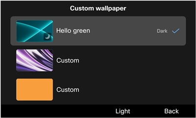
The following figure shows the Logo and Custom wallpaper setting screens:
Before you begin
Obtain the file path on the TFTP server that you've uploaded the wallpaper and logo images to.
| 1 |
Create a new file with your text editor or XML editor. |
| 2 |
Add the elements with the information of your image files included. The file path and file names are case-sensitive. Make sure you enter them correctly. |
| 3 |
Save the file as List.xml. |
Upload the List.xml file and all your wallpaper and logo image files to the TFTP server. After you apply the custom wallpaper settings on Cisco Unified Communications Manager, your phones download the images from the server.
Desktops/model-nameUpload your phone wallpaper images, logo image, and the List.xml file to the model-specific folder. Make sure the folder name matches your phone model. You can find the model name on the back of your phone. For example, DP-9851, DP-9861, DP-9861NR, DP-9871, DP-9871NR.
Desktops/480x800x24Upload your KEM wallpaper images to this folder.
| 1 |
On Cisco Unified Communications Manager Administration, select Cisco Unified OS Administration in the Navigation field and click Go. 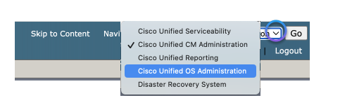
|
| 2 |
Select . |
| 3 |
Click Choose File and select the file to upload in your local drive. |
| 4 |
Specify the upload directory for the wallpaper image. |
| 5 |
Click Upload File. |
| 6 |
Repeat Step 3 through Step 5 to upload more files. |
What to do next
Restart the TFTP server.
To apply the changes that you've made, restart the TFTP server.
| 1 |
On Cisco Unified Communications Manager Administration, select Cisco Unified Serviceability in the Navigation field and click Go. |
| 2 |
Navigate to . |
| 3 |
Select your server and click Go. |
| 4 |
Select Cisco TFTP in the CM Services section. |
| 5 |
Click Restart. |
As an administrator, you can designate the wallpaper image that will be applied to the deployed phones. If you grant users access to the appearance settings on their phones, they can choose whether to display the logo and select their preferred wallpaper from the provided options. However, if you do not grant them access, the appearance settings will be hidden on the phones.
Before you begin
Before you start configuring the wallpaper settings on Cisco Unified Communications Manager Administration, finish the following actions first:
- Prepare your wallpaper and logo images
- Create a general management file (List.xml)
- Upload the List.xml file and the image files to the TFTP server
| 1 |
Log in to Cisco Unified Communications Manager Administration. |
| 2 |
Navigate to . |
| 3 |
Locate and click the profile that your phones are using. |
| 4 |
In the Common Phone Profile Information section, check the check box of Enable End User Access to Phone Background Image Setting if you want to allow users to change the phone screen background image. Otherwise, leave the check box unchecked. |
| 5 |
Go to the Product Specific Configuration Layout section and enter the filename of the wallpaper image file in the Background Image field. It's important to enter the exact filename that you specified in the List.xml file. If you enter a wrong filename, the system will fail to load the wallpaper. |
| 6 |
Click Save and then Apply Config. |
| 7 |
Restart the phones. |
In addition to uploading a prepared XML file to a TFTP server, you can also directly send an XML request to the phone to customize the wallpaper of the phone and KEM screens.
| 1 |
Log in to Cisco Unified Communications Manager Administration. | |||||||||||||||||||||
| 2 |
Do one of the following actions as needed:
| |||||||||||||||||||||
| 3 |
Set Phone Personalization to Enabled. | |||||||||||||||||||||
| 4 |
Associate the phone to the user. | |||||||||||||||||||||
| 5 |
Prepare an HTML file that contains the XML information specified for customized wallpaper. Here's an example of the HTML file:
| |||||||||||||||||||||
| 6 |
Save and file to your local disk, and open it with a web browser, and then click the button. The wallpaper will be pushed to the phone. When the configuration is complete, the users can view and set the wallpaper as usual on the phone screen.
| |||||||||||||||||||||
| 7 |
(Optional) To remove the custom wallpaper from the phone, do the following: |
Action button on 9800 Series
The Action button is the red button located at the top-right of the phone. It allows users to quickly access designated services, such as emergency or custom services. You can custom the button to initiate events that suit your specific use cases.
Customize the Action button
The custom options for the Action button on Cisco Desk Phone 9800 Series require specific PhoneOS firmware support. See the following table for details:
| Feature | Required firmware version |
|---|---|
| Emergency call | PhoneOS 3.0.1 and later |
| Custom service | PhoneOS 3.2.1 and later |
| Multiple triggers | PhoneOS 3.3.1 and later |
| HTTP Post | PhoneOS 3.3.1 and later |
| Multiple events on a single trigger | PhoneOS 3.4.1 and later |
| 1 |
Log in to Cisco Unified Communications Manager Administration. |
| 2 |
Do one of the following actions as needed:
The configuration follows a hierarchical structure:
|
| 3 |
Customize the Action button settings with the following parameters based on your use cases. There are three groups of parameters for the Action button, each corresponding to a service with a unique trigger. If a service trigger is specified in multiple groups, the settings in Group 1 take priority over those in Group 2 and 3, while Group 2 takes priority over Group 3.
For more information about these parameters, see Parameters for the Action button. |
| 4 |
Select Save. |
| 5 |
Select Apply Config. |
References
Parameters for the Action button
The parameters are available in Enterprise Phone Configuration, Common Phone Profile, and individual phone configuration.
| Parameter | Default and options | Description |
|---|---|---|
| Action Button Function 1~3 |
Default: Off Options: Off, Emergency Call, Custom |
You can configure the button with a specific service.
When you set the field to Emergency Call or Custom, make sure that you enter the service destination in the Action Button Service Destination field. Or, the phone will display a configuration error. |
| Action Button Service Name 1~3 |
Default: Empty |
Optionally specify a name for the service associated with the Action button. This name will be displayed in the on-screen message when the user presses the button, indicating which service will be triggered. If you don't specify a name, the default name will be Emergency call, Silent emergency call, or Custom action based on your selection in the Action Button Function field. |
| Action Button Service Destination 1~3 |
Default: Empty |
Provide the service destination in one of the following formats based on the service assigned to the Action button:
If you enable the Action button without setting a valid service destination, the user on the phone will see a message prompting for configuration. After the user closes this notification, the warning icon will persist in the header of the phone screen until the button is properly configured or disabled. Phone numbers cannot be used as destinations for custom services. If you
configure the Action Button as Custom and enter a phone
number as the service destination, an alert message will display on the phone
indicating that the button is unconfigured. Instead, you can add a phone
number in this format If you are not allowed to input a URL including ampersand (&), use %26 as a replacement. For example, enter http://1.2.3.4/phone?a=1%26b=2%26c=3 instead of http://1.2.3.4/phone?a=1&b=2&c=3. |
| Custom Content Field 1~3 |
Default: Empty |
This setting works only when the Action Button Function is set to Custom. Enter the HTTP data such as method, header, and post content, with a maximum length of 1024 characters. When configured, the phone sends an HTTP Post request when the Action is pressed. If the service requires
authentication to access, make sure to enter the authentication secret in the
Service Secret field. In the HTTP data, use the macro
For examples and the syntax, see HTTP Post request for the Action button. |
| Service Secret 1~3 |
Default: Empty |
A service secret can be an authentication secret, token or password. The
entered secret is displayed as a masked string and can be referenced using the
macro |
| Service Trigger 1~3 |
Default: Single Press Options: Single Press, Long Press, Press 3 times |
Choose how users can place an emergency call or initiate a custom service using the phone's Action button. Single Press: Press the Action button to trigger the associated call or service. Long Press: Press the Action button down for at least 2 seconds to trigger the associated call or service. Press 3 times: Press the Action button three times with intervals of less than 2 seconds between each press to trigger the associated call or service. Don't repeat a trigger across multiple services, as the parameters with lower priority will not function. The priority order, from highest to lowest, is as follows: Group 1, Group 2, Group 3. |
| Dial Out Delay 1~3 |
Default: 5 Options: 0 - 30 |
Set the timeout period, in seconds, for the phone to initiate an emergency call or a custom action after the Action button is pressed. Set it to 0 if you prefer the phone to place the call or initiate an event immediately upon detecting the trigger, as specified by a single press, long press, or triple presses on the button. |
| Silent Emergency Call 1~3 |
Default: Disabled Options: Enabled, Disabled |
Silent emergency call is designed for discreet assistance in dangerous situations. It enables users to seek help without making any noise.
|
| Allow Silent Emergency Call Retrieval |
Default: No Options: Yes, No |
Controls whether users can retrieve phone functionality during a silent emergency call. By default, once a silent emergency call is initiated, the phone locks all functions until the call recipient ends the call. When this parameter is set to Yes, users can press any key to restore normal phone operation while maintaining the emergency call. The call audio remains silent unless the user increases the volume using the Volume key. |
HTTP Post request for the Action button
The Action button on Cisco Desk Phone 9800 Series can be configured to trigger XML applications through HTTP Post requests.
In Custom Content Field, enter your customized request script. You
can specify either XML or JSON content type and include macros in the request. For example,
$SScan be added to the script to retrieve the authentication secret,
token, or password provided in the Service Secret field.
The following examples are in XML and JSON:
Sample #1: XML
--method POST
--header 'Content-Type: application/xml'
--header 'Authorization: Bearer username:$SS'
--body '<MetaData><Trigger>True</Trigger><Description>This is for HTTP POST XML</Description></MetaData>'

Sample #2: JSON
--method POST
--header 'Content-Type: application/json'
--header 'Authorization: $SS'
--body '{"events":[{"evtid":"12345", "parameters": {"trigger":true}, "Description":"This is for HTTP POST JSON"}]}'
Cisco Unified Communications Manager (UCM) requires percent encoding for the reserved characters in accordance with RFC 3986.
| Character | Percent encoding |
|---|---|
| & | %26 |
| ' | %27 |
| " | %22 |
| < |
%3c |
| > |
%3e |
The following script is an example using percent-encoded strings.
--method POST
--header %27Content-Type: application/xml%27
--body %27%3cMetaData%3e%3cTrigger%3eTrue%3c/Trigger%3e%3cDescription%3eThis is for HTTP POST XML%3c/Description%3e%3c/MetaData%3e%27| Macro name | Macro expansion |
|---|---|
| #DEVICENAME# | The device name displayed in the calling system. For example, SEP845A3EC21288 |
| $SS | Service Secret which presents a masked string in the phone configuration page, such as authentication secret, token, or password. |
Configure help desk for 9800 phones
You can enable the help desk feature and configure quick numbers for the phone users.
| 1 |
In the Cisco Unified Communications Manager Administration, select one of the following windows:
|
| 2 |
Navigate to the Product Specific Configuration Layout area and set the following fields:
|
| 3 |
Click Save. |
Enable ThousandEyes integration for 9800 phones
ThousandEyes Agent integration for phones supports the following models:
| Phone model | Firmware version |
|---|---|
| Cisco Desk Phone 9861 | 3.2.1 and later |
| Cisco Desk Phone 9871 | 3.2.1 and later |
Supported features
On ThousandEyes portal, you can view the following information related to phones:
- Scheduled tests
- Dynamic tests for meetings on Webex, Microsoft Teams, and Zoom via Office 365 calendar
- Dynamic tests for SIP calls
- Local networks
The Webex, Microsoft Teams, or Zoom meetings that you join through the phone are using Session Initiation Protocol (SIP). When setting up tests for your phones on the ThousandEyes application, make sure that you use the Webex template, instead of other meeting app templates.
Limitations
- Phone Wi-Fi statistics aren't available on the ThousandEyes portal.
- The Run Once option for instant tests isn't supported in PhoneOS 3.2.1.
- Real user tests are not supported for phones.
Before you begin
-
Get ThousandEyes Endpoint Agent licenses (either essential or advantage) You need one endpoint license per device.
-
Get the connection string from the ThousandEyes application.
-
Install the device package for your Unified Communications Manager version to make the ThousandEyes related parameters available. Download the device package at the CallManager Support page.
| 1 |
Log in to Cisco Unified Communications Manager Administration. |
| 2 |
Do one of the following actions as needed:
|
| 3 |
Set ThousandEyes Enable to True. |
| 4 |
Copy the connection string from the ThousandEyes application and paste it into the Connection String field. |
| 5 |
Select Save. |
| 6 |
Select Apply Config. |
Office Hours
The Office Hours feature lets phones automatically power on, power off, or turn off the display based on a set schedule, helping organizations save energy, reduce costs, and optimize device performance. The information on this page applies to Cisco Desk Phone 9800 Series and Cisco Video Phone 8875 registered with Cisco Unified Communications Manager.
Two power-saving options are available on the phone to reduce power consumption during periods of inactivity.
Display Off Mode
When the Office Hours feature is enabled, the phone turns off its display according to the configured schedule. Users can light up the display by pressing any key on the phone.
Deep Sleep Mode
In Deep Sleep Mode, the phone automatically powers down during the designated periods. You can choose to enable Deep Sleep Mode exclusively for non-workdays, or for both non-workdays and non-working hours on workdays.
To wake up the phone, perform the appropriate action for your phone model:
 Press the Select button on the Navigation Cluster.
 Tap the Home button.
 Press the Power button.
While in Deep Sleep Mode, no calls, including emergency calls, can be made on the phone; and the Action button on the top-right of the device isn't accessible.
| Feature | 8875 | 9811 | 9841 | 9851 | 9861 | 9871 |
|---|---|---|---|---|---|---|
|
Display Off | Yes | No | Yes | Yes | Yes | Yes |
|
Deep Sleep (Controlled by phone) | No | No | Yes | Yes | Yes | Yes |
|
Cisco Smart Power (Deep Sleep controlled by switch) | Yes | Yes | Yes | Yes | Yes | Yes |
Enable your phone to manage its own power modes
By default, the Office Hours feature is enabled on your phone. The default office hours are set to 7:00 to 19:00 from Monday to Friday. The phone turns off the screen outside of the designated hours. You can customize working hours, workdays, and the power-saving modes — Display Off and Deep Sleep.
| 1 |
Log in to Cisco Unified Communications Manager Administration. |
| 2 |
Do one of the following actions as needed:
The configuration follows a hierarchical structure:
|
| 3 |
Customize working hours and workdays to reflect the business hours of your users.
See more information about these parameters , see Parameters for Office Hours. |
| 4 |
Configure the settings for Display Off Mode for both working hours and non-working hours. Cisco Desk Phone 9811 doesn't support Display Off Mode.
See more information about these parameters , see Parameters for Office Hours. |
| 5 |
Configure the settings for Deep Sleep Mode for the 9800 Series phones. Deep Sleep Mode on Cisco Video Phone 8875 and Cisco Desk Phone 9811 can only be enabled by Cisco switches through the smart power feature. To configure the smart power settings, follow the steps in Allow Cisco switch to manage power modes for your phone (smart power).
See more information about these parameters , see Parameters for Office Hours. |
| 6 |
Select Save. |
| 7 |
Select Apply Config. |
Allow Cisco switch to manage power modes for your phone (smart power)
The smart power feature allows Cisco Smart Switches to manage the phone's power modes via Power over Ethernet (PoE).
You can choose to let the switch manage the phone's power modes based on the schedules configured on the switch. The following table shows how the smart power settings interact with the phone's own Deep Sleep and Display Off settings configured in the phone's calling system.
| Smart Power | Smart Power Override | Description |
|---|---|---|
| Disabled | Yes / No |
Smart power is disabled. The phone follows the power saving configuration set on its calling system. |
| Enabled for non-work day only | No |
Smart power is enabled only on non-work days. On non-work days, the phone follows the display off and deep sleep schedules configured on its calling system. The switch wakes the phone from deep sleep following the phone's schedule. |
| Yes | Smart power is always enabled. Since Smart Power Override is set to Yes, the switch manages the phone's display off and deep sleep modes based on the schedules configured on the switch. The phone's own settings in its calling system are overridden. | |
| Enabled for all days | No |
Smart power is always enabled. The phone follows the display off and deep sleep schedules set on its calling system. The switch wakes the phone from deep sleep following the phone's schedule. |
| Yes | Smart power is always enabled. Since Smart Power Override is set to Yes, the switch manages the phone's display off and deep sleep modes based on the schedules configured on the switch. The phone's own settings in its calling system are overridden. |
Before you begin
-
Your phone uses Power over Ethernet (PoE) as the power source. If a power cube is connected, the smart power feature is automatically disabled.
-
Your phone is connected to a Cisco Smart Switch C9350 with IOS XE 17.18.2 or later.
- To use the Smart Power feature, you must first enable the office hours feature on your phone.
- Your Unified CM (UCM) cluster must be running version 14 or a later version and with the appropriate device package installed.
| 1 |
Log in to Cisco Unified Communications Manager Administration. |
| 2 |
Do one of the following actions as needed:
The configuration follows a hierarchical structure:
|
| 3 |
Configure the following parameters:
|
| 4 |
Select Save. |
| 5 |
Select Apply Config. |
Parameters for Office Hours
| Parameter | Default and options | Supported model | Description |
|---|---|---|---|
| Office Hours parameters | |||
| Enable Office Hours |
Default: Enabled Options: Enabled, Disabled |
8875 9841 9851 9861 9871 |
Check this option to enable the Office Hours feature for Cisco Desk Phone 9800 Series. The Office Hours feature is designed to minimize power usage during inactivity periods on the phone. You can configure the phone to automatically turn off the screen (Display Off Mode) or power off (Deep Sleep Mode) outside of the designated working periods. |
| Work Days |
Default: Monday through Friday |
8875 9811 9841 9851 9861 9871 |
Customize the workdays by holding down the Ctrl key and selecting the desired days. During non-workdays, the phone will automatically turn off the screen. By default, workdays are set from Monday to Friday. This setting also applies to Deep Sleep Mode, if enabled. If you choose to enable Deep Sleep Mode exclusively for non-workdays, the phone will power off during those days. If you enable Deep Sleep Mode for all days, the phone will power off during both non-workdays and non-working hours on workdays. Set working hours for workdays using the Working Hour Start and Working Hour End fields. |
| Working Hours Start |
Default: 07:00 |
8875 9811 9841 9851 9861 9871 |
Set the start time for working hours using the 24-hour format. Outside of the specified working hours, the phone will automatically turn off the screen, or enter Deep Sleep Mode only when Deep Sleep is set to Enabled for All Days. Examples: 09:00 for 09:00 am; 17:30 for 05:30 pm |
| Working Hours End |
Default: 19:00 |
8875 9811 9841 9851 9861 9871 |
Set the end time for working hours using the 24-hour format. Outside of the specified working hours, the phone will automatically turn off the screen, or enter Deep Sleep Mode only when Deep Sleep is set to Enabled for All Days. Examples: 09:00 for 09:00 am; 17:30 for 05:30 pm Ensure that the interval between the start and end time longer than 60 minutes. |
| Display Off Parameters | |||
| Display Off During Office Hours |
Default: Disabled Options: Disabled, In 1 minute, In 5 minutes, In 30 minutes |
8875 9841 9851 9861 9871 |
Enable or disable Display Off Mode during office hours. This feature is disabled by default, keeping the phone screen always on during office hours. To enable this feature, select a timeout duration from the available options. For example, if set to "In 5 minutes", the phone screen will automatically turn off after 5 minutes of inactivity. The LED indicator follows the setting of LED Indicator In Display Off Mode. |
| Display Off Idle Timeout Outside Office Hours |
Default: 5 Options: 1-60 |
8875 9841 9851 9861 9871 | Set the timeout period in minutes for the phone to automatically turn off the screen after being awakened during Display Off Mode. |
| LED Indicator In Display Off Mode |
Default: Enabled Options: Enabled, Disabled |
8875 9841 9851 9861 9871 |
This setting determines whether to turn off the Front Arc LED on 9800 Series or the Home button LED on 8875 when the phone enters Display Off Mode, both during or outside office hours. By default (Enabled), the LED remains illuminated after the phone enters Display Off Mode. When set to disabled, the LED is off in Display Off Mode. |
| Line Key and Top 360 LED in Display Off Mode |
Default: Disabled Options: Disabled, Enable Line Key LED, Enable Top 360 LED, Enable both Line Key and Top 360 LED |
9841 9851 9861 9871 | Controls whether the LEDs light up to notify users of phone statuses in Display Off mode. When disabled, both the Line Key LEDs on phone and Key Expansion Module (KEM) and Top 360 LEDs are off. When the corresponding LED is enabled, its indication behavior is the same as when the display is on. You can configure this parameter in the phone configuration XML file (cfg.xml) by entering a string in this format: <Line_Key_and_Top_360_LED_In_Display_Off_Mode ua="na">Disabled</Line_Key_and_Top_360_LED_In_Display_Off_Mode>This setting works only when the LED Indicator In Display Off Mode parameter is set to Enabled. |
| Handset LED in Display Off Mode |
Default: Disabled Options: Enabled, Disabled |
8875 | Controls whether the handset LED lights up to notify users of phone statuses in Display Off mode. When disabled, the handset LED is off. When enabled, its indication behavior is the same as when the display is on. You can configure this parameter in the phone configuration XML file (cfg.xml) by entering a string in this format: <Handset_LED_In_Display_Off_Mode ua="na">Disabled</Handset_LED_In_Display_Off_Mode>This setting works only when the LED Indicator In Display Off Mode parameter is set to Enabled. |
| Deep Sleep Parameters When smart power isn't applied, the Deep Sleep settings work with the office hours settings to determine the deep sleep schedule on 9841, 9851, 9861, and 9871. When smart power is applied and Smart Power Override is disabled, the switch also uses these settings to control the deep sleep mode on all applicable phones. | |||
| Deep Sleep |
Default: Disabled Options: Disabled, Enabled for Non-Workdays Only, Enabled for All Days |
9841 9851 9861 9871 |
Enable or disable Deep Sleep Mode on the phone. This feature automatically powers off the phone during specified time periods. This option works only when the Enabled Office Hour option is checked. When disabled, the phone will not enter Deep Sleep Mode. If set to Enabled for Non-Workdays Only, the phone will power off exclusively on non-workdays. For the specified workdays, the phone will turn off the screen outside of the specified working hours. If set to Enabled for All Days, the phone will power off during both non-workdays and non-working hours on workdays. Set working hours for workdays using the Working Hours Start and Working Hours End fields. |
| Enter Deep Sleep After Working Hour End |
Default: 60 Options: 0 - 360 |
8875 9811 9841 9851 9861 9871 | Set the timeout period, in minutes, for the phone to automatically power off
after the time specified in the Working Hours End field. If
you want the phone to enter Deep Sleep Mode immediately after working hours, set it
to 0. The smart power feature uses this setting to control the phone's power mode only when Smart Power Override is disabled. |
| Wakeup From Deep Sleep Before Working Hour Start |
Default: 60 Options: 0 - 360 |
8875 9811 9841 9851 9861 9871 | Set the timeout period for the phone to wake up from Deep Sleep Mode before the
time specified in the Working Hours Start field. If you want
the phone to wake up until working hours start, set it to 0. The smart power feature uses this setting to control the phone's power mode only when Smart Power Override is disabled. |
| Deep Sleep Idle Timeout |
Default: 5 Options: 0 - 60 |
8875 9811 9841 9851 9861 9871 |
This setting applies to the following two scenarios:
The following notes apply to both scenarios described above.
|
| Enable Deep Sleep Audible Alert |
Default: Unchecked |
8875 9811 9841 9851 9861 9871 |
Enable or disable the phone to play audio tone to alert the user before it enters Deep Sleep Mode. |
| Smart Power Parameters Supported only on phones powered by Power over Ethernet (PoE). | |||
| Smart Power |
Default: Disabled Options: Disabled, Enabled for Non-work Day Only, Enabled for All Days |
8875 9811 9841 9851 9861 9871 |
Enable or disable the smart power feature. By default, smart power is disabled. Set it to Non-work Day Only or All Days as needed to enable this feature. The setting is effective only when a valid domain and security secret are provided. |
| Smart Power Override |
Default: No Options: Yes, No |
8875 9811 9841 9851 9861 9871 |
This setting determines whether the switch can override the phone's power-saving configuration set by the calling system.
|
| Smart Power Domain | Default: Empty |
8875 9811 9841 9851 9861 9871 |
The smart power domain that the phone belongs to. Max 128 characters. |
| Smart Power Endpoints Security Secret | Default: Empty |
8875 9811 9841 9851 9861 9871 |
The password (shared secret) used for communication between the phone and the switch. Max 128 characters. |
Configure your phones for emergency calls (E911)
You can configure the E911 location service on Cisco phones to have an active location URI for emergency calls. The location of the phone can contain the street address, building number, floor number, room number, and other office location information. When you dial an emergency number, the emergency responder receives the phone location and a call-back number. If an emergency call disconnects, the emergency service uses the call-back number to reconnect to the caller.
Before you begin
Obtain an E911 location URL and a company ID for the phone from your emergency calling service provider (for example, Redsky admin).
| 1 |
Sign into Cisco Communication Manager Administration as an administrator. |
| 2 |
Enable E911 service for the phone: |
| 3 |
Configure a service profile: |
| 4 |
Associate an end user with the service profile (configured in Step 2): |
| 5 |
Create or modify an SIP dial rule for the emergency number: |
| 6 |
Associate a phone with the user (configured in Step 3) and the SIP dial rule (Configured in Step 4): |
| 7 |
Add the SIP Trunk to a RedSky server: |
| 8 |
Configure route pattern to route E911 calls: |
| 9 |
Upload RedSky certificates to CUCM: |
Set up Do Not Disturb
When Do Not Disturb (DND) is turned on, either no audible rings occur during the ringing-in state of a call, or no audible or visual notifications of any type occur.
One exception is the Multilevel Precedence and Preemption (MLPP) call. The user still receives the priority calls on the phone even though the DND is turned on.
You can configure the phone with a softkey template with DND as one of the selected features.
For more information, see the " Configure Software-Based Endpoints" chapter in System Configuration Guide for Cisco Unified Communications Manager, Release 11.5(1) or later.
| 1 |
Sign into Cisco Unified Communications Manager Administration as an administrator. |
| 2 |
Select . |
| 3 |
Locate the phone that you will set up. |
| 4 |
Navigate to the Do Not Disturb pane, set the following parameters:
For the parameters DND Option and DND Incoming Call Alert, both can be found in the Common Phone Profile window () and the Phone Configuration window (). The setting in the Phone Configuration window takes precedence. |
| 5 |
Click Save. |
Set up forward all
You can set up the phone to redirect incoming calls to another phone number or to your voicemail by using the Cisco Unified Administration Manager.
| 1 |
Sign into Cisco Unified Communications Manager Administration. |
| 2 |
Select . |
| 3 |
Locate the phone that you will set up. |
| 4 |
Select the target line from the Association pane. |
| 5 |
Navigate to the Call Forward and Call Pickup Settings pane, enter a forwarded-to destination number in the field Forward All. |
| 6 |
Click Save. |
Enable E911 services on your phones
Historically, Cisco Emergency Responder (CER) and RedSky have worked together to provide compliant E911 services. As an alternative, we now offer another method for connecting to RedSky using HELD. Beginning with PhoneOS release 4.0.1, this new method of using HELD with E911 services are disabled on phones by default and must be manually enabled in CUCM before users can access them. Before enabling E911 with this new HELD method, it is important to carefully assess all dependencies and perform a comprehensive end-to-end evaluation of your infrastructure.
-
The Webex App using HELD+ and PhoneOS devices using HELD can't coexist within the same architecture.
-
The E911 setting described on this page don't work with Cisco Emergency Responder (CER) and requires appropriate licensing and provisioning from the third-party E911 service provider.
Before you begin
Before enabling E911 services on your phones, make sure that E911 has been properly provisioned in CUCM by following the procedures in Feature Configuration Guide for Cisco Unified Communications Manager.
| 1 |
Log in to Cisco Unified Communications Manager Administration. |
| 2 |
Perform one of the following actions as needed:
The configuration follows a hierarchical structure:
|
| 3 |
Set HELD Support for Third-Party E911 to Enabled. The default setting is Disabled. |
| 4 |
Click Save. |
| 5 |
Click Apply Config. |
Set up join and direct transfer
You can set up the Join and Direct Transfer feature on a phone. If you enable the feature, the users can quickly add a person into a conference call or transfer a call through the Calls tab displayed in the new call session. You can also change the scope of the calls listed in the tab.
| 1 |
Do one of the following actions from Cisco Unified CM Administration:
|
| 2 |
Set up the field Join And Direct Transfer Policy:
|
| 3 |
Click Save. |
Add speed-dial numbers
Phones registered with Cisco Unified Communications Manager support the following two types of speed-dial numbers:
-
Speed dials: These are assigned to line keys and also appear in the Speed Dials list. Users can call the associated number by pressing the configured line key or by selecting it from the list. The number of supported speed dials depends on the number of physical and virtual line keys available on the phone.
-
Abbreviated dials: These allow users to dial the assigned short index to place a call to the associated number using the Abbr Dial softkey. The phone doesn't display an abbreviated dials list. The maximum number of supported abbreviated dials is up to 199.
| 1 |
In Cisco Unified Communications Manager Administration, select . |
| 2 |
Locate the phone that you will set up. |
| 3 |
In the Phone Configuration window, select Add a new SD. A Speed Dial Configuration window appears, which contains settings for both speed dials and abbreviated dials.
|
| 4 |
Enter valid speed-dial numbers in the Number fields and a label in the Label fields. |
| 5 |
Click Save. |
What to do next
Ensure that you add Abbreviated Dial (AbbrDial) to the softkey template for Off Hook and Digits After First states in the Cisco Unified CM Administration.
Configure Application Dial Rules
Cisco Unified Communications Manager supports application dial rules that allow you to add and sort the priority of dialing rules for applications. Application dial rules automatically strip numbers from or add numbers to telephone numbers that the user dials. For example, the dial rules automatically add the digit 9 in front of a 7-digit telephone number to provide access to an outside line.
| 1 |
In Cisco Unified Communications Manager Administration, go to . |
| 2 |
Click Add New to create a new application dial rule, or choose an existing application dial rule to edit it. |
| 3 |
Fill in the following fields:
|
| 4 |
Click Save. |
Configure park monitoring
Park monitoring is supported only when a phone parks a call. Park monitoring then monitors the status of a parked call. The park monitoring call alert does not clear until the parked call gets retrieved or is abandoned by the parked call. This parked call can be retrieved by using the same call alert on the phone that parked the call.
For more information about how to configure park monitoring in Cisco Unified Communications Manager, see Feature Configuration Guide for Cisco Unified Communications Manager, Release 12.5(1) or later.
Cisco Unified Communications Manager Administration provides three cluster-wide service
timer parameters for park monitoring: Park Monitoring Reversion Timer,
Park Monitoring Periodic Reversion Timer, and Park Monitoring
Forward No Retrieve Timer. Each service parameter includes a default and requires
no special configuration. These timer parameters are for park monitoring only; the
Call Park Display Timer and Call Park Reversion Timer
are not used for park monitoring. See the following table for descriptions of these
parameters.
Configure the timers in the Cisco Unified Communications Manager Service Parameters page.
| 1 |
In Cisco Unified Communications Manager Administration, choose. | ||||||||
| 2 |
Select a server for the phone and the service Cisco CallManager (Active). | ||||||||
| 3 |
In the Clusterwide Parameters (Feature - General) section, set the fields as described in the following table.
|
The Directory Number Configuration window contains a Park Monitoring area where you can configure the three parameters.
| 1 |
In Cisco Unified Communications Manager Administration, choose . | ||||||||
| 2 |
Click Find and select the directory number on which you want to configure the park monitoring. | ||||||||
| 3 |
In the Park Monitoring section, set the fields as described in the following table.
|
When a call that was routed via the hunt list is parked, the Park Monitoring
Forward No Retrieve Destination parameter value is used (unless it is empty) when
the Park Monitoring Forward No Retrieve Timer expires.
| 1 |
In Cisco Unified Communications Manager Administration, choose . |
| 2 |
Click Find and select the hunt pilot on which you want to configure the park monitoring. |
| 3 |
Set the Park Monitoring Forward No Retrieve Destination parameter. If the field is empty, the call forwards to the destination that is configured in the Directory Number Configuration window when the Park Monitoring Forward No Retrieve Timer expires. |
Set up hold reversion
When the user places an active call on hold and the configured time limit expires, the Cisco Unified Communications Manager generates an alert on the phone, such as ring or beep, to remind the user to handle the call. The held call becomes a reverted call when the hold duration exceeds the configured time limit. For more information about the Hold Reversion feature, see Features and Services Guide for Cisco Unified Communications Manager.
Set up music on hold
When the user places an active call on hold, the held call plays a music streamed from the Music on Hold server. For more information about the Music On Hold feature, see Features and Services Guide for Cisco Unified Communications Manager.
Set up call recording
You can enable the call recording feature on a phone so that the users can record an active call or call conference.
Only the user who triggers the call recording might receive an audible alert to indicate that the call is being recording. The other connected parties don't receive any audible alert for the recording.
You can set whether the alert sound will be audible to both the user who triggers the recording and to other connected parties.
When an active call is being recorded, the user can receive or place intercom calls. However, if the user places an intercom call, the active call is put on hold. This action causes the recording session to terminate.
For more information, see the Monitoring and Recording section in Feature Configuration Guide for Cisco Unified Communications Manager, Release 15 and SUs.
| 1 |
In Cisco Unified Communications Manager Administration, add the softkey Record (Record). For more information, see Configure feature soft buttons with a softkey template.
|
| 2 |
Apply the new or updated softkey template to a phone. For more information, see Apply a softkey template to a phone.
|
| 3 |
Enable Built in Bridge field for the phone. |
| 4 |
Configure a phone line for recording. |
Set up password protection for the settings menu
You can secure the phone settings menu with the password protection. Once enabled, the users are required to provide the correct password to access the settings menu.
| 1 |
Sign into Cisco Unified Communications Manager Administration as an administrator. |
| 2 |
Select |
| 3 |
Locate the profile that you want to set up. |
| 4 |
Navigate to the Common Phone Profile Information pane and set up a password in the Local Phone Unlock Password field. |
| 5 |
Click Save. |
| 6 |
Click Apply Config. |
| 7 |
Restart the phones. |
Record call log from shared line
You can determine whether to record a shared line call in the call history. When enabled, users can recognize the shared call in the call history by the keyword "remote".
| 1 |
In Cisco Unified Communications Manager Administration, select . |
| 2 |
Locate the phone that you will set up. |
| 3 |
In the Product Specific Configuration Layout section, configure the field Record Call Log from Shared Line to enable or disable the feature. Default value: Disabled
|
| 4 |
Click Save. |
Set up barge
You can set up the phone to allow a user to join a remotely active (conference) call on a shared line.
For more information about how to set up barge in Cisco Unified Communications Manager, see Feature Configuration Guide for Cisco Unified Communications Manager, Release 12.5(1) or later.
Set up privacy on shared lines
You can set up the privacy on shared lines to determine whether the users to view the call status and to barge into a call or conference.
For more information about how to set up the privacy feature in Cisco Unified Communications Manager, see Feature Configuration Guide for Cisco Unified Communications Manager, Release 12.5(1) or later.
Set up Malicious Call Identification (MCID)
You can configure the Malicious Call Identification (MCID) feature to track troublesome or threatening calls. Users can report these calls by requesting that Cisco Unified Communications Manager (Unified CM) identify and register the source of the incoming call in the network.
For more information about how to set up MCID in Cisco Unified CM, see Feature Configuration Guide for Cisco Unified Communications Manager, Release 14 and SUs.
Enable LED indication for missed calls
By default, the Top 360 LED is disabled for missed calls. You can enable the LED indication if you want to receive the missed call alerting more explicitly. Typically, you can find the missed call on the phone screen.
This topic is only available for Cisco Desk Phone 9800 Series.
Before you begin
| 1 |
Log in to Cisco Unified Communications Manager Administration. |
| 2 |
Do one of the following actions as needed:
|
| 3 |
Set Missed Call Led Alert to Enabled. Default: Disabled.
|
| 4 |
Select Save. |
| 5 |
Select Apply Config. |
Enable voicemail LED indicators for other lines
By default, the Top 360 LED lights up only on the primary line when the phone has new voicemails. You can also enable the LED indicator for other lines (non-primary lines) on the phone.
| 1 |
In Unified Communications Manager Administration, select . |
| 2 |
Locate the phone that you will set up. |
| 3 |
In the left Association area, click Add a New DN to create a new directory number or click an existing directory number to modify it. The Directory Number Configuration window displays.
|
| 4 |
In the Line <n> on Device section, set the Visual Message Waiting Indicator Policy to Light and Prompt. |
| 5 |
Configure the remaining fields in the Directory Number Configuration window. |
| 6 |
Click Save. The setting takes effect on the configured line.
|
| 7 |
(Optional) If you want to apply the settings on the corporate level, do the following: |
Configure Cisco IPMA
The Unified Communications Manager Assistant feature is a plug-in that an assistant can use to handle calls on behalf of a manager, intercept manager calls, and route them appropriately.
Manager Assistant supports up to 3500 managers and 3500 assistants. To accommodate this number of users, you can configure up to three Manager Assistant applications in one Unified Communications Manager cluster and assign managers and assistants to each instance of the application.
Manager Assistant supports shared line support and proxy line support.
For information about administration configuration for IPMA, see Manager Assistant in Feature Configuration Guide for Cisco Unified Communications Manager
Control the settings menu access
As an example, the Settings menu on Cisco Desk Phone 9811, 9841, 9851, and 9861 includes the following configuration menus.
- Recents: Shows the recent calls list where the user can view, edit, or delete the call history.
- EM: Signs in to a different phone in your network and have it act the same as your phone if extension mobility is configured.
- About this device: Shows basic information about the phone device.
- Issues and diagnostics: Displays whether the phone has any issue. Provides the statistics information of the phone. Provides the menu for the users to submit problem reports.
- User preferences: Provides settings for the audio, Bluetooth, and screen:
- Audio: Specifies a different ringtone to a specific line, adjusts audio volume, and configures the noise removal feature.
- Bluetooth: Enables or disables the Bluetooth connectivity.
- Screen: Adjusts the phone's default brightness. Customize the appearance, including logo, wall paper, and color theme if available.
- Network and service:
- Network settings: Provides options for viewing and configuring network settings such as Wi-Fi and Ethernet.
- Network status: Provides an overview of the network connectivity.
- Security setup: Provides options for viewing and configuring security settings such as security mode and Locally Significant Certificate (LSC) update.
- Restart and reset:
- Restart: Restarts the phone.
- Reset security certificate: Resets security certificate to factory defaults.
- Factory reset: Restores the phone to factory settings. All data will be erased and the user must reactivate the phone after the factory reset.
You can control whether a phone has full or partial access to the Settings menu by using Cisco Unified Communications Manager Administration.
| 1 |
In Cisco Unified Communications Manager Administration, select . |
| 2 |
Locate the phone that you will set up. |
| 3 |
Navigate to the Product Specific Configuration area and set the Settings Access field.
|
| 4 |
Select Save. |
| 5 |
Select Apply Config. |
| 6 |
Restart the phone. |
 Allows access only to the following menus.
Set up date and time group
You can select a predefined date and time group for a device pool in Cisco Unified Communications Manager Administration. If your desired group is not in the list, you can create a new group or modify an existing one.
| 1 |
In Cisco Unified Communications Manager Administration, select . |
| 2 |
Locate the device pool that you need to set up. |
| 3 |
Navigate to the Roaming Sensitive Settings area and select a group from the Date/Time Group field. |
| 4 |
Select Save. |
| 5 |
(Optional) If you want to create or modify a Date/Time group, do the following: |
Set up wideband codec
By default, the G.722 codec is enabled for your phone. If Cisco Unified Communications Manager (Unified CM) is configured to use G.722 and the far endpoint supports G.722, the call connects using the G.722 codec in place of G.711.
This situation occurs regardless of whether the user has enabled a wideband headset or wideband handset. If either the headset or handset is enabled, the user may notice greater audio sensitivity during the call. Greater sensitivity means improved audio clarity but also means that the far endpoint can hear more background noise, such as rustling papers or nearby conversations. Even without a wideband headset or handset, some users may find the additional sensitivity of G.722 distracting.
The Advertise G.722 and iSAC Codec service parameter affects whether wideband support exists for all devices that register with this Cisco Unified CM server or for a specific phone.
| 1 |
To configure wideband support for all devices: |
| 2 |
To configure wideband support for a specific device: |
Set up the audio and video port range for 8875 phones
Audio and video traffic can be sent to different RTP port ranges in order to improve Quality of Service (QoS).
The following fields control the port ranges in Cisco Unified Communications Manager Administration:
-
Audio ports
-
Start Media Port (default: 16384)
-
Stop Media Port (default: 32766)
-
-
Video ports
-
Start Video (This is to set the video start port).
Minimum: 2048
Maximum: 65535
-
Stop Video (This is to set the video stop port)
-
Minimum: 2048
-
Maximum: 65535
-
-
The following rules apply when configuring the video port fields:
-
After the Start Video RTP Port and Stop Video RTP Port are configured, the phone uses ports within the video port range for video traffic. The audio traffic uses the media ports.
-
If the audio and video port ranges overlap, the overlapped ports carry both audio and video traffic. If the video port range isn’t configured correctly, the phone uses the configured audio ports for both audio and video traffic.
For more information, see the documentation for your particular Cisco Unified Communications Manager release.
| 1 |
In Cisco Unified Communications Manager Administration, select |
| 2 |
Set the Start Media Port and Stop Media Port fields for the audio port range. |
| 3 |
Select Save. |
| 4 |
Navigate to one of the following windows: |
| 5 |
Set the Start Video RTP Port and Stop Video RTP Port fields for the range of ports required. The value for Stop Video RTP Port must be at least 16 larger than the value for Start Video RTP Port. |
| 6 |
Select Save. |
Video transmit resolution supported on 8875 phones
Cisco Video Phone 8875 supports the following video formats:
-
1080p (1920x1080)
-
720p (1280x720)
-
600p (1024x600)–Default
-
WVGA (800x480)
-
VGA (640x480)
-
360p (640x360)
-
CIF (352x288)
-
240p (432x240)
-
SIF (352x240)
-
QCIF (176x144)
The phone negotiate the best bandwidth and resolution based on the phone configuration and phone screen limitations.
The following table shows the resolutions, frames per second, and video bit rate range for each of the supported video types.
|
Video type |
Video resolution |
Frames per second (fps) |
Video bit rate range |
|---|---|---|---|
| 1080p | 1920 x 1080 | 30 | 3500–4000 kbps |
| 1080p | 1920 x 1080 | 15 | 2667–4000 kbps |
|
720p |
1280 x 720 |
30 |
2040–3750 kbps |
|
720p |
1280 x 720 |
15 |
1185–3750 kbps |
| 600p | 1024 x 600 | 30 | 1584–3000 kbps |
| 600p | 1024 x 600 | 15 | 840–3000 kbps |
|
WVGA |
800 x 480 |
30 |
990–1500 kbps |
|
WVGA |
800 x 480 |
15 |
525–1500 kbps |
|
VGA |
640 x 480 |
30 |
520–1500 kbps |
|
VGA |
640 x 480 |
15 |
280–1500 kbps |
|
360p |
640 x 360 |
30 |
600–1350 kbps |
|
360p |
640 x 360 |
15 |
315–1350 kbps |
|
240p |
432 x 240 |
30 |
270–525 kbps |
|
240p |
432 x 240 |
15 |
96–525 kbps |
|
CIF |
352 x 288 |
30 |
200–350 kbps |
|
CIF |
352 x 288 |
15 |
120–350 kbps |
|
SIF |
352 x 240 |
30 |
200–350 kbps |
|
SIF |
352 x 240 |
15 |
120–350 kbps |
|
QCIF |
176 x 144 |
30 |
94–350 kbps |
|
QCIF |
176 x 144 |
15 |
64–350 kbps |
|
QCIF | 176 x 144 | 15 | 17–350 kbps |
Enable web access for a phone
You can enable web access for a Cisco Unified IP Phone.
For more information about how to enable web access for a phone in Cisco Unified Communications Manager, see Feature Configuration Guide for Cisco Unified Communications Manager, Release 12.5(1) or later.
Use problem report tool
Users can submit problem reports to you with the Problem Report Tool.
The Problem Report Tool logs are required by Cisco TAC when troubleshooting problems. The logs are cleared if you restart the phone. Collect the logs before you restart the phones.
To issue a problem report, users access the Problem Report Tool and provide the date and time that the problem occurred, and a description of the problem.
If the PRT upload fails, you can access the PRT file for the phone from the URL
http://<phone-ip-address>/FS/<prt-file-name>. This
URL is displayed on the phone in the following cases:
- If the phone is in the factory default state. The URL is active for 1 hour. After 1 hour, the user should try to submit the phone logs again.
- If the phone has downloaded a configuration file and the call control system allows web access to the phone.
- The Customer Support Upload URL field isn't configured correctly.
You must add a server address to the Customer Support Upload URL field on Cisco Unified Communications Manager.
- The phone isn't assigned with an IP address.
If you are deploying devices with Mobile and Remote Access (MRA) through Expressway, you must also add the PRT server address to the HTTP Server Allow list on the Expressway server.
You must use a server with an upload script to receive PRT files. The PRT uses an HTTP POST mechanism, with the following parameters included in the upload (utilizing multipart MIME encoding):
- devicename (example: “SEP001122334455”)
- serialno (example: “FCH12345ABC”)
- username (the username configured in Cisco Unified Communications Manager, the device owner)
- prt_file (example: “probrep-20141021-162840.tar.gz”)
A sample script is shown below. This script is provided for reference only. Cisco does not provide support for the upload script installed on a customer's server.
<?php
// NOTE: you may need to edit your php.ini file to allow larger
// size file uploads to work.
// Modify the setting for upload_max_filesize
// I used: upload_max_filesize = 20M
// Retrieve the name of the uploaded file
$filename = basename($_FILES['prt_file']['name']);
// Get rid of quotes around the device name, serial number and username if they
          exist
$devicename = $_POST['devicename'];
$devicename = trim($devicename, "'\"");
$serialno = $_POST['serialno'];
$serialno = trim($serialno, "'\"");
$username = $_POST['username'];
$username = trim($username, "'\"");
// where to put the file
$fullfilename = "/var/prtuploads/".$filename;
// If the file upload is unsuccessful, return a 500 error and
// inform the user to try again
if(!move_uploaded_file($_FILES['prt_file']['tmp_name'], $fullfilename))
        {
header("HTTP/1.0 500 Internal Server Error");
die("Error: You must select a file to upload.");
}
?>
| 1 |
Set up a server that can run your PRT upload script. |
| 2 |
Write a script that can handle the parameters listed above, or edit the provided sample script to suit your needs. |
| 3 |
Upload your script to your server. |
| 4 |
In Cisco Unified Communications Manager, go to the Product Specific Configuration Layout area of the individual device configuration window, Common Phone Profile window, or Enterprise Phone Configuration window. |
| 5 |
Check Customer support upload URL and enter your upload server URL.
Example:
http://example.com/prtscript.php |
| 6 |
Save your changes. |
IPv6 ready logo setup
Define the IPv6 interface identifier for the device. The interface identifier you choose, either MAC or Opaque, will determine the method that is used for generating part of the IPv6 address. This is applicable to both link-local IPv6 addresses and Stateless Address Auto Configuration (SLAAC) addresses. The address contains a 64-bit prefix and a 64-bit interface identifier generated by the device. With MAC, an EUI-64 based interface identifier is generated, as described in RFC-2373. With Opaque, a random 64-bit interface identifier is generated as described in RFC-7217 on the first boot of the device, and this is used forever, or until factory reset.
Set the phone to always display the multi-line interface
The Always Use Multi-line Mode parameter is only available on Cisco Desk Phone 9841, 9851, and 9861. It ensures a consistent user experience by forcing the phone to always display the multi-line layout.
By default, the phone displays the multi-line interface only when multiple lines or other line key features are configured. When Always Use Multi-line Mode is enabled, the phone uses the multi-line layout even if only a single line is configured.
| 1 |
Log in to Cisco Unified Communications Manager Administration. |
| 2 |
Do one of the following actions as needed:
The configuration follows a hierarchical structure:
|
| 3 |
Set the Always Use Multi-line Mode field to Enabled. |
| 4 |
Select Save. |
| 5 |
Select Apply Config. |
Enable xAPI on your phones
xAPI is a set of APIs used to monitor, manage, and control PhoneOS-based devices. In this release, we are introducing xAPI as a new option for customers and partners to manage phones and build custom solutions. Customers and partners can access xAPI through HTTP or HTTPS.
Cisco Desk Phone 9811 doesn't support this feature on PhoneOS 4.0.1 or earlier.
The following features are now supported on phones registered to Webex Calling, Cisco Unified CM, or Cisco BroadWorks:
-
Retrieve basic device information and status, and subscribe to phone events
-
Perform device reboot and factory reset
-
Simulate hard key presses and screen touch operations
-
Capture device screens
-
Initiate calls
For information about the supported xAPIs and the related documentation, see https://phoneos.cisco.com.
Before you begin
- Your phone is running PhoneOS 3.5 or a later version.
- Your Unified CM (UCM) cluster must be running version 14 or a later version and with the appropriate device package installed.
- Prepare an HTTP client and HTTP server for feedback collection.
| 1 |
Log in to Cisco Unified Communications Manager Administration. |
| 2 |
Do one of the following actions as needed:
The configuration follows a hierarchical structure:
|
| 3 |
Configure the following parameters:
|
| 4 |
Select Save. |
| 5 |
Select Apply Config. |
Enable 9800 Series to use the video capability on Webex
The Companion mode allows the phone to participate in video meetings or calls by using the Webex App for video. Users can send and receive video or share content through the Webex App while keeping audio on the phone.
By default, this feature is enabled on the phone.
Before you begin
- The phone is running PhoneOS 3.6 or a later version and registered in personal mode. This feature isn't supported on Workspace phones.
- Your Unified CM (UCM) cluster must be running version 14 or a later version and with the appropriate device package installed.
- The user is running Webex App 45.11 or later on Windows OS. This feature isn't supported on Webex App for macOS.
| 1 |
Log in to Cisco Unified Communications Manager Administration. |
| 2 |
Do one of the following actions as needed:
The configuration follows a hierarchical structure:
|
| 3 |
Set Video Capability on Webex to Enabled. |
| 4 |
Select Save. |
| 5 |
Select Apply Config. |
Set minimum ringer volume
You can define a minimum ringer volume for phones to help ensure incoming calls are not missed. When configured, attempts to reduce the ringer volume below the minimum are blocked.
| 1 |
Log in to Cisco Unified Communications Manager Administration. |
| 2 |
Go to . |
| 3 |
Do one of the following actions as needed:
The configuration follows a hierarchical structure:
|
| 4 |
Choose a value from the Minimum Ring Volume drop-down list. The default setting is 0-Silent, which allows users to mute the
ringer. If a minimum volume is set, the phone will display a notification when users reach
the minimum level.
|
| 5 |
Select Save. |
| 6 |
Select Apply Config. |
Configure MARI and FEC for media quality
By default, Media Adaptation and Resilience Implementation (MARI) and Forward Error Correction (FEC) are enabled on your phones to dynamically maintain optimal media quality.
MARI monitors the network conditions in real time and dynamically executes corrective algorithms to maintain optimal quality of experience in lossy networks. MARI may apply Rate Adaptation or Forward Error Correction based on network conditions.
FEC is a resilience mechanism used to recover lost packets without the need for retransmission. FEC adds extra packets to the original media stream so that the media receiver can reconstruct the missing data with these packets to provide better audio or video quality in lossy networks.
Because FEC increases bandwidth usage, it may negatively impact media quality in congested or bandwidth-constrained networks. You can decide whether to disable it based on your network conditions.
| 1 |
Log in to Cisco Unified Communications Manager Administration. |
| 2 |
Go to . |
| 3 |
Do one of the following actions as needed:
The configuration follows a hierarchical structure:
|
| 4 |
Enable or disable MARI and MARI FEC based on your network conditions. |
| 5 |
Select Save. |
| 6 |
Select Apply Config. |


